
|
|
Forum Index : Electronics : BMS Revisited
| Page 1 of 3 |
|||||
| Author | Message | ||||
| Solar Mike Guru Joined: 08/02/2015 Location: New ZealandPosts: 1123 |
In the process of re-designing my battery management system, now that we have moved to Lead Carbon Cells @6 volts, 8 in series for the 50 volt bank; the Lifepo4 BMS design needs re-visiting. As an aid for initially getting all 24 of these batteries to the same state of charge prior to assembling the bank, I want the BMS to have a cell balance load capability of 3.5 - 4 amps. This will allow connecting up any 8 cells in series to a current limited fixed voltage supply, the new BMS will ensure they all charge evenly and still charge reasonably quickly, will use a 300W PV panel + small up-converter as the charger (no AC power on site). Have decided to make this system modular, the cell sense balance boards especially are all identical, for 6v cells only require 8 monitor points, however if someone else wants to use 3.2v Lifepo4 then 16 will be required. Initially was going to construct a small pic based cpu board placed across each cell in the bank, with opto connected serial bus to talk to a master controller. But having made the decision to have a high dissipating cell balance load it makes better sense to run suitably rated wires to each cell via a 10 amp fuse and multi-pin connector on the other end; plug this into a central unit with large heat sink + fans etc. This setup has the advantage of allowing changes to the system without having to mess around in the battery bank eg. there was some discussion here last year about transformer balancing, still want to do this, and easier to accomplish having all electronics in the one place, just swap out the balance boards with new ones. Here is the design for each cell sense\balance module, they will sit vertically and plug into a mother-board. 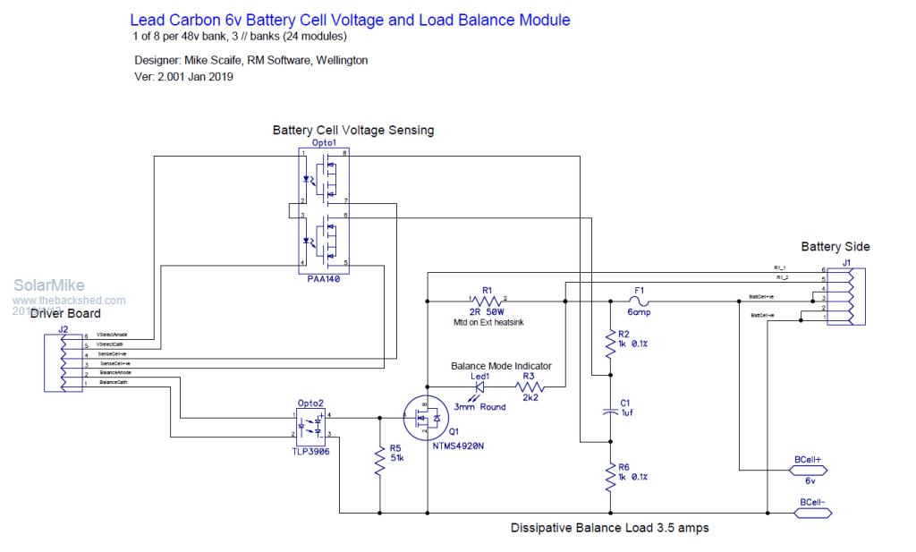 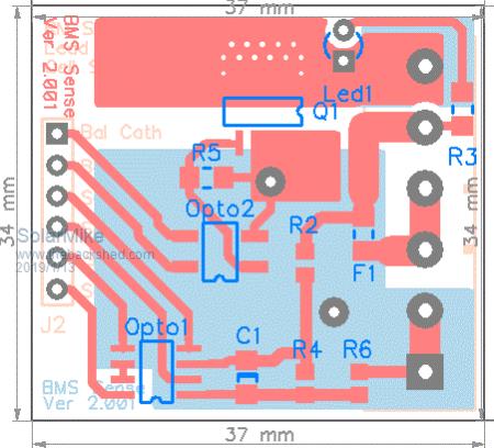 Each cell module is opto-coupled to the mother-board driver, using optimos switches to select each battery cell in the bank, if the main driver is also running off an isolated power rail then essentially the driver is connected directly across each cell. OnSemi make some neat LED driver chips that are serial driven, they make connection to the cell modules very easy, a single resistor selects the led current to the module opto-couplers. Will have the CPU board plugin also to allow a PIC or Arduino etc. 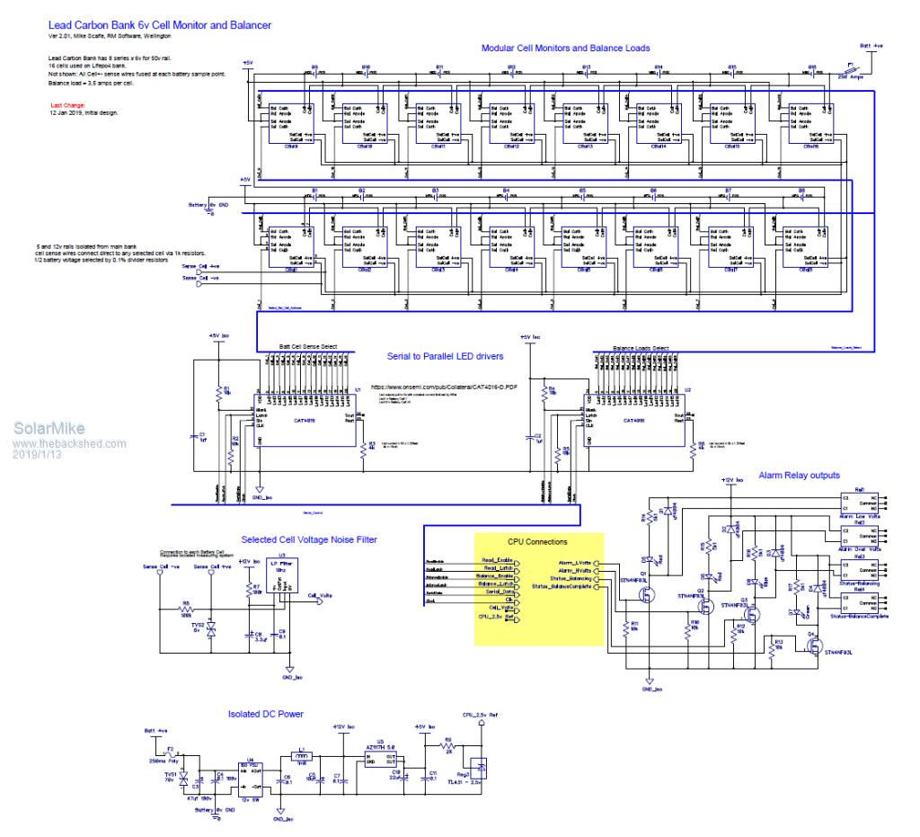 2019-01-13_162248_BMS_DriverSchematic.pdf The driver-CPU board floats up and down across the battery bank, so any external connections to it will have to be via data-bus isolators or opto-couplers. Cheers Mike |
||||
| nickskethisniks Guru Joined: 17/10/2017 Location: BelgiumPosts: 410 |
Always a pleasure to following your projects! I'm working on a simular project for LTO and lifepo4 battery. I'm using Laa125 optomos, I think it's cheaper but a bit slower. For the active balancing, I've build something for 2 cells and it works great, it's modular so I need to make more boards for expanding and testing the setup. It's something simular then wiseguy suggested. I will soon post a photo. |
||||
| davef Guru Joined: 14/05/2006 Location: New ZealandPosts: 499 |
Impressive! Are you familiar with the ISL94023? My SBMS has several error conditions which I am not processing at the moment. To quote out of the SBMS-060 manual" I recall a lot of negative comments about early LiFePO4 battery balancers and what happens if they fail. Is there a forum around that focuses on lead-carbon batteries? Thanks, Dave |
||||
| Solar Mike Guru Joined: 08/02/2015 Location: New ZealandPosts: 1123 |
Yes I did look at those series of chips, probably several years ago, they seemed too complicated to me back then, also I don't think they handle cell voltages above 6v so wouldn't work in this application. Shame the SBMS only does 12\24 volts, otherwise I may have ordered one on the Kick-Starter project. Fully aware of the pitfalls of balancers blowing up and taking the pack and perhaps the house with it, nothing good engineering and always have a fallback to plan B cannot fix. Don't know of any LC forums, must be some out there by now, all storage batteries are extremely overpriced and expensive here in NZ, the lead carbons were same cost as normal sealed gel batteries, don't know why more people are not using them. Cheers Mike |
||||
| Warpspeed Guru Joined: 09/08/2007 Location: AustraliaPosts: 4406 |
I have chased this around for a long time solving various problems as they arose, but now finally have something I am completely happy with. The first thing is a simple way to show at a glance the current situation of every cell. This displays current cell voltages and also has a peak hold feature that shows the absolute maximum and minimum cell voltages ever reached for thirty Lithium cells. 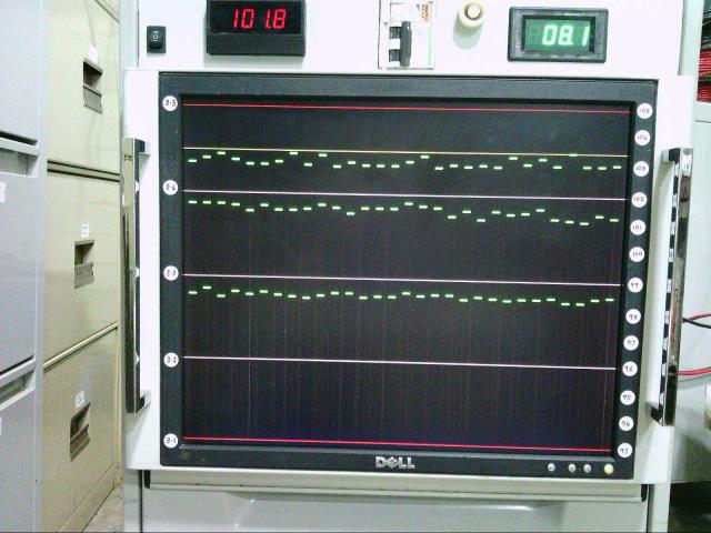 This does not use a power hungry PC or laptop, but the X-VGA video is generated in hardware from a slow microcontroller. The whole BMS monitoring system only requires 1.5 watts of power (with the 17 inch Dell turned off). The high speed VGA generating part of it is all just a few 74HC counters, gates and flip flops. Only 1K of green only video ram gives 32 x 256 resolution. Each green block is one large pixel blob. Single individual video lines are turned on and off to create the red, yellow and white graticule lines. I originally started out with a central cell balancing system, but ran into all kinds of problems when trying to combine that with a cell voltage monitoring system. Apart from voltage drops in the wiring, cell voltages vary hugely depending on if it is charging or discharging, and a high powered cell balancer can really screw up the voltage monitoring. Its much better to discharge an individual cell continuously at 200mA than discharge one cell at a time sequentially at 6 amps for one thirtieth of the time. So I no longer use centrally measured cell voltages to control a central cell balancer, it opens up a whole can of worms. Individual cell balancers themselves obviously need to all be adjusted the same, and that takes a bit of care. If you have ever tried to manually balance cells it can be a frustrating business. You can bring a low cell up, or a high cell down so its like the others. But after a few subsequent charge and discharge cycles it will tend to revert to a certain extent back to how it was before you tried to balance it. Giving it "a bit more" can set it off going in the opposite direction. After much hair tearing frustration, a very slow, low powered discharge balancer sitting across each individual cell now does a far better long term job. Over weeks and months I can see the cell to cell variations very gradually become less and less. And really that it is all its required to do. If you start off with new cells they should be good enough to put straight into service, even if the cell voltages are not exactly the same. Nibbling away at that slowly, seems to work much better than trying to fix it more violently with selective short bursts of very high current. Whenever I have tried that, it always just makes things worse. Something very slow and fully automatic has been much more successful here. In the above picture, things are now just starting to get back to normal after I tried to hurry things up a bit, about a week or so ago, and that only made things worse. Cheers, ĀTony. |
||||
| Solar Mike Guru Joined: 08/02/2015 Location: New ZealandPosts: 1123 |
Wow, I like your monitoring method there Tony, have made no decision what we will be using, perhaps a MMite with graphical display with serial data connection to the driver controller. Your concerns for cell measurement accuracy when balancing loads are applied are real and valid, as all balance wires are same length and area, calculations show 3% sensed cell voltage drop with load, 4.5% with an adjacent cell loaded and 6% both adjacent cells also loaded and 1.5%, 3% with no load but adjacent cells loaded. Software can manage these calc's easily as cpu knows what cells have loads on them; as long as they work out to +- 0.25% I will be happy. Balancing wont occur very often, so will see how it works out long term, the heat-sinked wire wound load resistors can easily be altered to allow lower balance currents if necessary. Cheers Mike |
||||
| Warpspeed Guru Joined: 09/08/2007 Location: AustraliaPosts: 4406 |
Its not just the resistance in the wiring, but the cell characteristics. Suppose you take a soundly sleeping Lithium cell that has been neither charged or discharged for several hours. And assume it rests at 3.350 volts. As soon as you try to charge it, even at very low current, the voltage jumps up by some tens of millivolts over a minute or two. That voltage is not real. If you cease charging it will drop back to 3.350v over several tens of minutes. Same if you apply a small load to a sleeping cell. The voltage will quickly fall by some tens of millivolts. And relatively quickly bounce back up when the load is removed. Now the problem is, if you are charging (or discharging) all of your series connected cells at identical current, but one individual cell is being either charged or discharged on top of that (to restore balance), you cannot rely on the cell voltages being made equal to indicate the actual state of cell charge. You can certainly force all the voltages to be equal with a balancer, but if the battery then rests, or goes back into either charge or discharge after some rest interval, cell the voltages will again become unequal. Its tough, because there is a very big difference in cell voltage around the zero resting voltage point, which is not really indicative of cell internal resistance. Suppose you switch in a ten amp load, the voltage might drop about 30mV and level off after about three minutes. If you increase that to 50 amps discharge, the voltage drops further, but not by very much. And it will then sit at 50 amps discharge for many hours with a very slow gradual fall away in voltage. That is the flat part of the discharge curve which is a truly wonderful thing. But around the zero current resting point the initial swing in voltage up and down is pretty dramatic, and its difficult to use as an indication of true cell balance while a cell is actually being balanced. I have had far more success by fitting individual carefully adjusted balancers, to each individual cell, and just watching the results of that on the cell voltage monitoring. Attempting to read all the cell voltages with software, and then selectively switching in either a central current source, or central current sink to the lowest and highest cells is like a dog chasing its tail. Things will certainly changing, but not necessarily improving. Cheers, ĀTony. |
||||
| Solar Mike Guru Joined: 08/02/2015 Location: New ZealandPosts: 1123 |
You could well be right, but I'm going to test this anyway.  Lead Carbon batteries terminal voltage is directly related to charge % and this balancing is only occurring during near full charge condition in the constant voltage charging phase, couldn't care less what is happening any other time. With these 6V batteries, the excess individual cell current will be dumped at 6.95 volts cell voltage point where the bank charge current is tapering down and similar to the individual cell dump current, so effectively allowing higher capacity lower voltage cells to catch up, voltages have to remain at this point for several hours, then switch to float. Using Lifepo4 cells where the upper charge knee is quite sharp, 3.5 volts is a good ending point, again the charger will be current limiting above 3.45 volts, when all cells reach the 3.5v point we switch to float immediately. Really I don't see any problem, the voltages are measured every 10 ms or so and balance loads can be dropped or applied at the same rate. Cheers Mike |
||||
| Warpspeed Guru Joined: 09/08/2007 Location: AustraliaPosts: 4406 |
That all sounds just about right. At ten amps, my cells rise from 3.45v to 3.50v volts in about sixty seconds. The extra charge absorbed in that extra minute will be minute, and just not worth the risk. Voltage rise is just explosive. I charge with a constant current up to about 3.40 volts only, then above that individual cells suddenly break into a sprint at some point, with some cell voltages quickly rising exponentially at a faster and faster rate. So what I do is taper the charging current, so full constant charge current up to around 3.40v, then a linear taper down of charge current to zero at 3.45v. Those voltages are the average for all thirty cells. Although the average may only ever reach 3.45v, a fast rising cell can easily just go ballistic and go way beyond that if not prevented. What actually happens is that some cells try to very rapidly sprint up to 3.45v while the more sluggish cells get quickly left way behind. The speed of rise of voltages of the faster rising cells is held in check by the steadily reducing charge current. As soon as any individual cell reaches exactly 3.45v all charging is terminated, and stays terminated. That is the yellow line on my display, and cell 27 is the one that turns off the charger at the moment, although several others are gradually creeping up, and one of them will eventually take over. Only total darkness and zero solar panel voltage resets the charging system for charging the next day. There is no float charge, I have read that float charging Lithiums is a definite no no. It charges up once each day then stops. The battery then sits idle, until late afternoon twilight provides insufficient solar to power the inverter directly off the solar panels. Once the charging shuts off the cell voltages all begin to fall back to about 3.40 volts naturally by themselves over about half to three quarters of an hour. The highest voltage cell taking the longest time to fall right back. And the lowest cell may not have advanced all that far above 3.40 volts anyway, when charging terminates. Each cell has a low current discharge circuit with about 10mV of hysteresis. Discharge starts at about 3.410v and switches off at 3.400v. The lower voltage cells quickly fall through this range and very little charge is lost in the discharge resistor. The higher voltage cells take much longer to discharge right back to 3.400v and much more of the charge is dissipated. This very gradual stealing of energy, top balances the cells, but very gradually over time. After about half to three quarters of an hour after the charger shuts off all cells will be sitting at the same 3.400 volts within about 3mV, regardless of what peak voltage they reached at charge termination. I have been playing around with this for months, and fine tuning the set points. Its all now finally working to my satisfaction. The cell voltages continue to converge, although the rate of convergence is notably slowing as the cells become closer in voltage at the end of charging. No doubt there are other workable strategies, perhaps even more effective ones. But this has worked out very well for me and is the direction that continual testing observation and development has lead me. My voltage display has 256 bit resolution, 1024 visible video lines, and 250 bits = 400mV span. So I can very easily see cell differences as low as 1.6mV. The red lines on the display activate a shunt trip on the battery circuit breaker (via software) if any cell dares to reach those levels. The peak hold function would tell me which cell caused the trip. The panel volt meter has under voltage and over voltage alarms that can also shunt trip the circuit breaker quite independently (via hardware) although that would be from the average cell voltage, and would only be the very last resort protection. Cheers, ĀTony. |
||||
| Solar Mike Guru Joined: 08/02/2015 Location: New ZealandPosts: 1123 |
>> What actually happens is that some cells try to very rapidly sprint up to 3.45v while the more sluggish cells get quickly left way behind. The speed of rise of voltages of the faster rising cells is held in check by the steadily reducing charge current. I have noticed that as well, my cells are 800AH so when charge currents taper down to the 10 amp range it takes a bit longer for them to all balance, about 1 hr or so currently with 300ma balance loads; thats one of the reasons for wanting to increase the loads, take less time.. >> There is no float charge, I have read that float charging Lithiums is a no no. Well lets put it another way, the non charge state (Float) is constant voltage from the charger at 3.35V\Cell, the cells wont really charge at this voltage, but when loads are applied to the bank the cells will want to drop down to near 3.3 to that long flat discharge region. The PV charger just supplies extra current that gradually increases as the bank discharges slightly, at the end of the day it is down about 5 AH from the fully charged state. Cheers Mike |
||||
| Warpspeed Guru Joined: 09/08/2007 Location: AustraliaPosts: 4406 |
I don't see time as being an issue. As long as the cells are converging rather than diverging in voltage over weeks months or years. That sounds fine. On a sunny day my 50Ah batteries are usually charged by mid morning and pull back to 3.40v by lunch time. They never fall below that. It would probably take one to two weeks for the battery under zero load to fall to 3.35v self discharge is very slow, it kind of flat lines at 3.40v and then just sits there. My discharge loads are 27 ohm one watt resistors, about 125mA but my battery is rather small. Cheers, ĀTony. |
||||
| nickskethisniks Guru Joined: 17/10/2017 Location: BelgiumPosts: 410 |
Is it smart to use that 1uF capacitor? There are 8 capacitors in parallel to charge(with 2kohm), won't it influence the measurement, or the rising/charging time of the capacitors? |
||||
yahoo2 Guru Joined: 05/04/2011 Location: AustraliaPosts: 1166 |
Congratulations Guys you are finally starting to get it nailed!  I kept telling myself that as soon as you got "hands on" with some decent cells and had a play it would all fall into place. I'm confused, no wait... maybe I'm not... |
||||
| Solar Mike Guru Joined: 08/02/2015 Location: New ZealandPosts: 1123 |
One RC per Cell (2k,1uf ceramic) = 2ms time constant, its only there to lower the impedance to HF noise, wont affect any readings. It is paralleled by another 2K on the driver board (latest schematic) to half the battery volts into the cell voltage filter, that's now running off 5v instead of 12, using 0.1% resistors. Cheers Mike |
||||
| Warpspeed Guru Joined: 09/08/2007 Location: AustraliaPosts: 4406 |
Noise is definitely going to be a problem. All those large cells, all that wiring, and heavy ripple current from the inverter, plus the one bit ambiguity of most analog to digital converters. I tried analog smoothing, but found it not to be as effective as hoped. I even tried some 1 Farad Ultracaps that had about 15 ohms of esr. Still had noisy bouncing bits. Software averaging was vastly more effective. I read my analog to digital converter 256 times with a delay in the loop so it took as close to 20mS to take all 256 readings as I could get it. Lovelly smooth repeatable noise free readings after that. Those optically isolated mosfet switches are slow, and you need to give them plenty of time to turn both fully on and fully off. I also multiplexed the drive to the opto switches. My thirty cells are physically arranged 6 x 5 so I needed only eleven wires to control 30 switches. And it still looks like a rats nest.... Cheers, ĀTony. |
||||
| Solar Mike Guru Joined: 08/02/2015 Location: New ZealandPosts: 1123 |
>> My thirty cells are physically arranged 6 x 5 so I needed only eleven wires to control 30 switches. And it still looks like a rats nest.... Just doing a tentative PCB layout now for the driver board, Rats Nest is one way of describing it... |
||||
| Warpspeed Guru Joined: 09/08/2007 Location: AustraliaPosts: 4406 |
I used one six way, and one seven way screw terminal block on my driver board, and two lengths of seven core light duty trailer cable to connect to the battery. Cheers, ĀTony. |
||||
| Solar Mike Guru Joined: 08/02/2015 Location: New ZealandPosts: 1123 |
Took awhile to do the PCB layout, bloody rats nest of connecting wires everywhere, having the battery sense component connections as plugin modules helps a lot. In the end used a Picaxe 20M2 cpu, all IO's used bar one. If I want to export the battery cell data to a master unit, will have to use a cpu with more IO's, 28X2 or similar and use opto couplers or data-isolator's onto something like a 1-wire bus. I think I need to start using Arduino chips, these Picaxes are quite expensive especially the 28/40 pin versions. TOP: 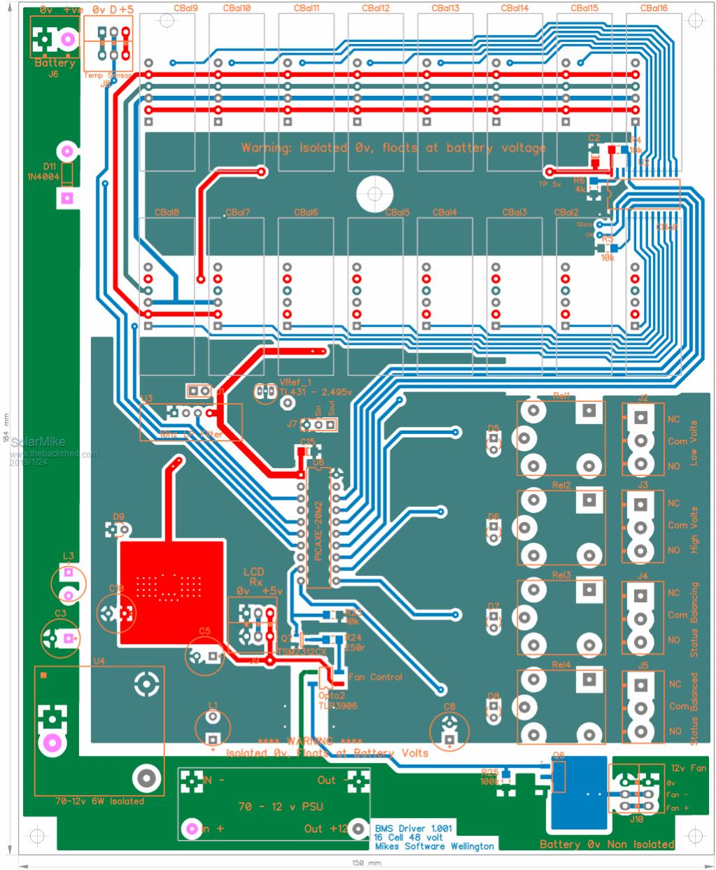 Bottom: 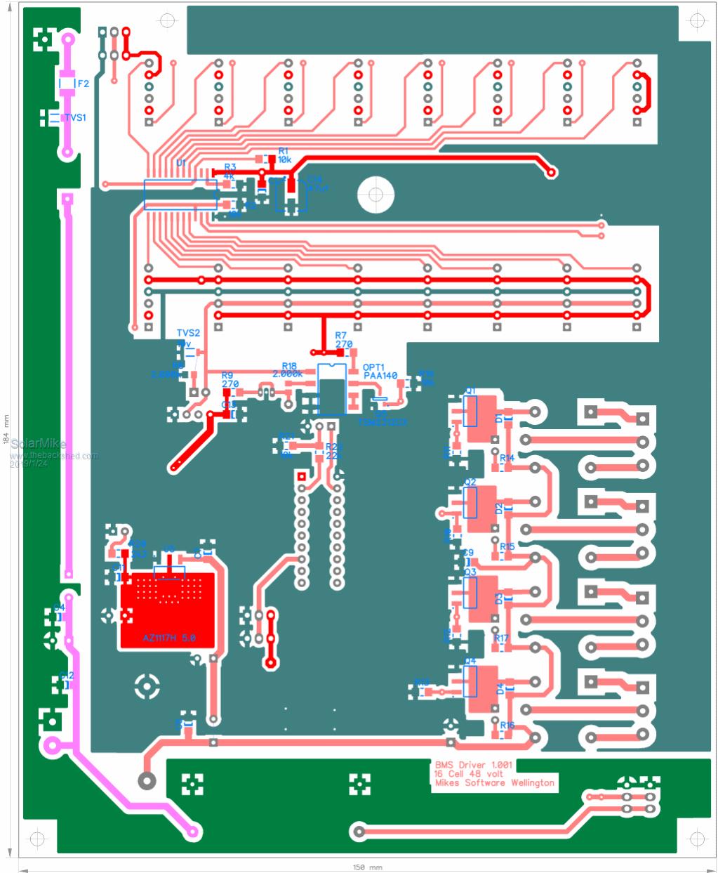 Cheers Mike |
||||
| Warpspeed Guru Joined: 09/08/2007 Location: AustraliaPosts: 4406 |
I had a similar problem, just ran out of i/o and pins on the processor. Had to use the serial PIO port pin to drive an external shift register. That can then be stretched right out to drive any number of output bits, its slow, but plenty fast enough for this kind of ultra slow motion battery cell sampling. I also fused both sides of every cell before the mosfet voltage sampling switches. I discovered that a 100mA M205 fast blow fuse will pop every time before the mosfet switches are damaged. If the software has a brain fart and crashes, there will be fuses flashing all over the place. A real pyrotechnic display. Fuses are cheap, the mosfet switches much less so. My score so far is an estimated 120 blown fuses and zero blown mosfet switches. The fuses fail open circuit which is a self limiting disaster. Mosfet switches invariably fail shorted, so if just one shorts out, it will probably take out every other in a cascading failure. A prospect too awful to even contemplate. Cheers, ĀTony. |
||||
| Solar Mike Guru Joined: 08/02/2015 Location: New ZealandPosts: 1123 |
I hope to avoid that scenario, all battery sense wires are fitted with 10a fuses at the battery to protect the cables. Each module board has a 6a resetting fuse for the balance load and 2k of voltage sense resistor prior to the switch, so max current that could flow assuming lowest and highest cell switches on simultaneously would be 25ma. I'm hoping that is enough to survive the probable initial programming stuff ups.  As there is already a common clock and data lines running to the switch mux's, I could add another serial//Parallel chip to control the relay's, thus giving me the extra IO's needed for Remote 1-Wire bus connection... We are developing a bunch of capacitive soil moisture sensors at the moment, need about 40 to get readings from test pots in the gardens, 500 meters of cable, will be using a 12 volt custom 1-wire bus for communications between them all and a master, the BMS will be an extension of that for remote display. Cheers Mike |
||||
| Page 1 of 3 |
|||||
