Notice. New forum software under development. It's going to miss a few functions and look a bit ugly for a while, but I'm working on it full time now as the old forum was too unstable. Couple days, all good. If you notice any issues, please contact me.
mackoffgrid Guru Joined: 13/03/2017 Location: AustraliaPosts: 460
Posted: 07:32am 23 Mar 2019
Copy link to clipboard
Print this post
Mark, apart from the waveform, does the inverter sound happy enough and the air-cond functions ok?
I've been running a 3.5k Mitsubishi inverter air cond off a Latrontics for years, I've never looked at the output though
cheers Andrew
renewableMark Guru Joined: 09/12/2017 Location: AustraliaPosts: 1678
Posted: 07:52am 23 Mar 2019
Copy link to clipboard
Print this post
Yeah it does Mack, you wouldn't know unless you looked at the wave on the scope.
It does look horrible though.
That worried me.
Just had the oven on for 1.5hrs, the torroid heated up to 35c, fans kicked on. Sine is perfectly smooth as you could want on every other load.Edited by renewableMark 2019-03-24Cheers Caveman Mark Off grid eastern Melb
renewableMark Guru Joined: 09/12/2017 Location: AustraliaPosts: 1678
Posted: 09:05am 23 Mar 2019
Copy link to clipboard
Print this post
Update, still running house nicely. Perfect wave, fan control works well, kicks in and out at setpoints. No flickering of lights. Only problem is the inverter air con.Cheers Caveman Mark Off grid eastern Melb
mackoffgrid Guru Joined: 13/03/2017 Location: AustraliaPosts: 460
Posted: 11:35am 23 Mar 2019
Copy link to clipboard
Print this post
It could be that All inverters would give the same waveform loaded by that Air Cond.
poida Guru Joined: 02/02/2017 Location: AustraliaPosts: 1392
Posted: 12:04pm 23 Mar 2019
Copy link to clipboard
Print this post
Good news, Mark. what temperatures are the heat sink and the toroid running at?
I also wonder about the current draw of the aircon. Since it's an inverter, maybe it has a primary DC bus supply that is using a switch to suck current at short intervals, about 9 times each 50Hz waveform. The period or duration it draws current is variable, depending on how much power it needs. A switch mode power supply as it were.
I'll bet the aircon draws huge amps, 9 times each 50 Hz but not for a long duration.
(Mark, if the aircon supply is via a 10 or 15A plug, I could come over with the mains current and voltage sense box, and we feed these signals into the CRO. We would see how the aircon current varies with time. I expect 9 big pulses each 50Hz)
This switchmode DC primary supply might also have some power factor correction stuff going on.
Anybody got a schematic for this or similar aircon?wronger than a phone book full of wrong phone numbers
renewableMark Guru Joined: 09/12/2017 Location: AustraliaPosts: 1678
Posted: 08:43pm 23 Mar 2019
Copy link to clipboard
Print this post
Poida, I set the nano to turn on at 35c and go off at 28c. This is very low but I wanted it to trip so it could be checked for operation.
Had the Ac on basically all day, then the oven was on for 1.5 hours. Heatsink and torroid didn't go past the 35c, the fans kept them within range.
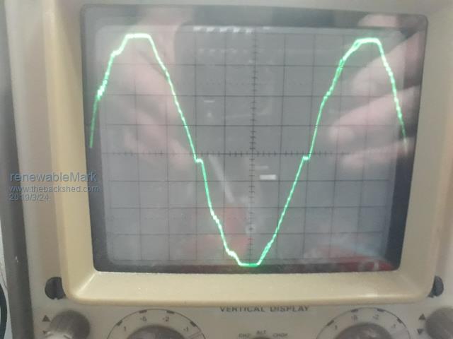
BTW when the air con is on full fan/power setting the wave just has a small blip at the crossover, it only turns the wave to crap when it's on a lower than full fan setting 1-4, on 5 it's fine.
But of course. someone just has to keep turning the bloody thing down don't they. Explain it 50 times that it upsets the machine, turn it back up, go out to garage to monitor then WHAM crap wave starts again. Go back inside, and well, what do you know the air con turned itself down again!!! Must have been a fairy? F
Then when it's sunset and no more excess power (from panels) someone starts complaining it's too hot inside and wants the ac on full blast. F! Rant over.
Poida the ac is hardwired, no plug unfortunately. Strangely it's in the same power circuit as some power points, I would have thought it would require it's own breaker.Cheers Caveman Mark Off grid eastern Melb
renewableMark Guru Joined: 09/12/2017 Location: AustraliaPosts: 1678
Posted: 09:11pm 23 Mar 2019
Copy link to clipboard
Print this post
Had another idea, as this has sync, I could finish off the second nanoverter or build a warp/cascade inverter to sync to. Maybe the extra grunt of two machines running would dampen the effect.Cheers Caveman Mark Off grid eastern Melb
brucedownunder2 Guru Joined: 14/09/2005 Location: AustraliaPosts: 1548
Posted: 02:11am 24 Mar 2019
Copy link to clipboard
Print this post
LOL, hahhaa, maybe the two machines would Dampen the effect ????
maybe a bottle of bundy would help ????.
Oh , sorry ,Ol mate, just giggling my arse off up here ,reading marks days of our lives,lol luv it ..
You'll get there mate,,don't know about the bundy but ???.
BruceBushboy
renewableMark Guru Joined: 09/12/2017 Location: AustraliaPosts: 1678
Posted: 05:15am 24 Mar 2019
Copy link to clipboard
Print this post
Yeah that makes sense, two sets of toroids would have more power to overcome the spikes placed upon them rather than one alone dealing with the spikes, that should dampen/smooth out the wave.
I thought you all might get a laugh about my struggles to educate others on off grid setups. That's a battle I'll never win I'm afraid.Cheers Caveman Mark Off grid eastern Melb
renewableMark Guru Joined: 09/12/2017 Location: AustraliaPosts: 1678
Posted: 06:27am 24 Mar 2019
Copy link to clipboard
Print this post
Well well, tried eco mode on the air con, that has a lower fan output setting.
Wave is still crap, but probably clean enough not to cause too much of a worry.
Cheers Caveman Mark Off grid eastern Melb
renewableMark Guru Joined: 09/12/2017 Location: AustraliaPosts: 1678
Posted: 04:19am 25 Mar 2019
Copy link to clipboard
Print this post
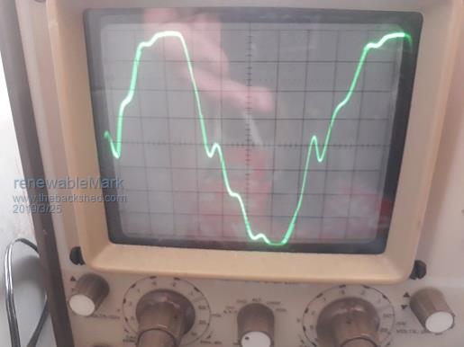
And here we have the wave while a microwave is running.
Looks like someone is building a Warpinverter next.
I never thought to check the wave with different things running, when you do you see how horrible they perform.
I should be able to get a second nanoverter built fairly quickly and sync the two together, heatsinks and second torroid are ready, but waiting for ferrite beads to fit on the fet gate legs to assemble another board.
A Warpinverter will be a while off.Edited by renewableMark 2019-03-26Cheers Caveman Mark Off grid eastern Melb
renewableMark Guru Joined: 09/12/2017 Location: AustraliaPosts: 1678
Posted: 04:54am 25 Mar 2019
Copy link to clipboard
Print this post
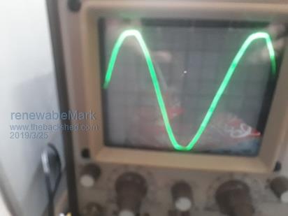
And the dryer, a big but gentle load on the machine.
There are also various plugpacks through the house charging various crap, but the big double stacked torroid with 4 secondaries of 128 turns doesn't seem to be worried about that.Cheers Caveman Mark Off grid eastern Melb
Mulver Senior Member Joined: 27/02/2017 Location: AustraliaPosts: 160
Posted: 09:47am 25 Mar 2019
Copy link to clipboard
Print this post
Can the Warpinverter back feed with a GTI to charge batteries as the PWM inverters can?
renewableMark Guru Joined: 09/12/2017 Location: AustraliaPosts: 1678
Posted: 10:18am 25 Mar 2019
Copy link to clipboard
Print this post
I don't know, I doubt it, but if we run a nanoverter that can do that, which will sync to the Warpinverter, so we have the power of two machines on the AC output, would the nanoverter still backfeed back to it's dc supply???
So if you have both machines sync'd on their AC outputs what happens when you feed excess power back into that "mini grid"? Magic smoke or would it take the path it's able to, ie back through the nanoverter????
Good question.....I'm a dunce and can't answer that.
Ahhh wishful thinking
If you have the nanoverters output set slightly lower excess flow should still go in that direction.
Got me stuffed, I have trouble opening cat food tins.Edited by renewableMark 2019-03-26Cheers Caveman Mark Off grid eastern Melb
Warpspeed Guru Joined: 09/08/2007 Location: AustraliaPosts: 4406
Posted: 02:51pm 25 Mar 2019
Copy link to clipboard
Print this post
Yes it certainly can, completely bi directional.Cheers, �Tony.
renewableMark Guru Joined: 09/12/2017 Location: AustraliaPosts: 1678
Posted: 08:40pm 25 Mar 2019
Copy link to clipboard
Print this post
Great news Tony, not that I have used that feature yet. I have a few GTI's lying around here but haven't got that far yet.
Since the machine has been running the house with the Nano card, (same Mad power board) something very odd has been happening with the battery voltage.
Normally in the morning the 630ah 48v FLA forklift battery sits around 50.0v, lately it's been 51v-51.5v and even after the morning get ready time it's sitting at 50.3v Central heating fan is currently running, lights on, kettle has been boiled twice, toaster has been run twice, fridge opened and closed a few times triggering it to run. So after all that, the battery v is still way above where it normally is when I get up first thing before any of that normally happens.
Gas central heating fan just turned off and battery went to 50.41v, I can hear fridge running.
Checked PV input and it's still zero, nothing at all yet.
Output voltage is set to 230v ac same as before.
No changes to battery or it's wiring.
Very odd, is it possible that the Nano makes it run more efficiently?
Just heard fridge tick off, central heating still off, battery went to 50.58v still have lights,tv, desktop pc on.
BTW for 6 months running the house with the Mad control 8010 card I checked the batt v every morning, so I understand the battery draining pattern fairly well. Edited by renewableMark 2019-03-27Cheers Caveman Mark Off grid eastern Melb
Tinker Guru Joined: 07/11/2007 Location: AustraliaPosts: 1904
Posted: 05:27am 26 Mar 2019
Copy link to clipboard
Print this post
Allow me to clear up something about synching AC power sources. We do that to increase the 'power' output available. Since AC power is a product of Volts times Amps times power factor (if applicable) we can see that voltage alone is not the thing that makes or breaks that connection.
Lets go back 200 years for a power sharing example that's easy to understand. Assume a coach and a team of horses to pull it. The horses could be mismatched , clydesdales and ponies , as long as they all progress at the same speed the coach moves along, each horse providing part of the pulling power. You can't have one horse galloping and the other walking .
Now translate the coach speed to frequency when talking about synching power sources (our inverters). As long as each source runs exactly in step with all the others (identical frequencies) each source contributes to the total power available.
If there is no external power drawn from that mini grid then they both just idle along at their synced frequency.
To sync them in the first place one power source has to play the master, frequency wise, and the other's frequency being slightly adjustable so both frequencies can be made to exactly coincide and lock together.
The warpinverter has a crystal controlled frequency so this is fixed and could play the master when paired with the nano version ozinverter.
The synching gets tricky when 'both' power sources's frequency could change, for example a rotary alternator (genny) and nano controlled inverter. If the genny can be run with a reliable, stable, frequency output up to its rated load then it should sync to the nano inverter and contribute available power.
I would monitor the output frequency under varying loads before attempting to sync it.
There must be some frequency sensing in the nano that detects when the genny is about to drop out of its stable frequency range due overloading, or stopping due run out of fuel, that disconnects the syncing relay instantly.
Now, what happens when we want to push power into our inverters to charge the battery? We know that a grid tie inverter can do that, its, after all, designed to push power into the grid. I'm comfortable with what happens in the inverter transformer, it is bi directional. What happens at the mosfets and how that AC at the transformer primary gets rectified there to charge the battery I dunno - and I'm not alone there .
I should guess a genny is not designed for the above - it does not do a full 60 seconds checking like a grid tie inverter does before connecting. So I think the genny would only be good for boosting the available power to the load if its synced to the nano inverter.
Some observation with my inverter set up. I have a small (1KW) Orion grid tie inverter to boost battery charging in the morning. While that happens the inverter AC voltage, normally set to 230V, drops to 225V. Any load on my mini grid seems to be powered by the grid tie inverter first, there is minimal charging from the MPPT controller if the batteries are nearly full. Bigger loads do draw power from all sources (battery, MPPT, grid tie inverter).
This works very well for me. The grid tie charging is just a "bang, bang" voltage sensing relay control, good enough for the initial boost charge I want it to perform.
The "bang, bang" switching is now done by IGBT's, they proved to be much more reliable than the mosfets madness specified when he first proposed that idea quite some time ago.
Klaus
Clockmanfr Guru Joined: 23/10/2015 Location: FrancePosts: 427
Posted: 07:26am 26 Mar 2019
Copy link to clipboard
Print this post
Comments from Oztules, 1st August 2015.
"The H bridge switching mos fets will synchronously switch the DC back through to the batteries from the AC from the grid ties... in the same way it switched the DC to quasi AC. ( @ >20khz or more )
This rectification is very much more efficient than diodes, as the silicon band gap is not there so you don't loose over .6v in the diode before you start...., instead the fets look like a short circuit at 3.7milliohms/6... or .6 milliohms... so current x .0006 gives the voltage losses... and so .06v x 100 amps or 6w per 5kw in the bridge arms.... very impressive... then some switching losses, but still seems pretty good in this format. ( or I^2 x R is 10000 x . 0006 = 6w per 5kw for 100 amps)
Looking at the scope wave forms, it seems to switch 80% on in 50ns... so losses are not too bad really."
40amp EMI Filters on the AC 230v inverter output.
"The EMI filters will have no effect on the back feeding... they only impede hf waves, not 50hz waves. To 50hz waveforms these are invisible. I prefer two stages...ie caps torroid, caps torroid,caps.... output... so two of those smaller ones in series and then paralleled for power
There will be a few in your grid tie for the same reasons.
................oztules"
I trust this helps. Everything is possible, just give me time.
3 HughP's 3.7m Wind T's (14 years). 5kW PV on 3 Trackers, (10 yrs). 21kW PV AC coupled SH GTI's. OzInverter created Grid. 1300ah 48v.
Tinker Guru Joined: 07/11/2007 Location: AustraliaPosts: 1904
Posted: 10:54am 26 Mar 2019
Copy link to clipboard
Print this post
LadyN Guru Joined: 26/01/2019 Location: United StatesPosts: 408
Posted: 05:50pm 26 Mar 2019
Copy link to clipboard
Print this post
So if the frequencies are in sync (so the zero crossing works) then the H bridge behaves like a synchronous active rectifier.
Since the MOSFETs have very low Rds_on, if saturated, they drop less than the expected 0.6V that rectifier diodes do.
The H bridge does not care where the current comes from, it's just a synchronous switch.
This is genius unless I misunderstood the whole thing in which case please let me know I am wrong.


 , as long as they all progress at the same speed the coach moves along, each horse providing part of the pulling power. You can't have one horse galloping and the other walking
  .
.