
|
|
Forum Index : Electronics : nanoverter build
| Author | Message | ||||
| tinyt Guru Joined: 12/11/2017 Location: United StatesPosts: 431 |
If you can hold off on your order until next week, I might be able to revise the gerbers to incorporate the corrections so that you don� t have to do the trace cuts and jumpers. |
||||
| poida Guru Joined: 02/02/2017 Location: AustraliaPosts: 1388 |
that would be great, tinyt, I can wait. wronger than a phone book full of wrong phone numbers |
||||
| tinyt Guru Joined: 12/11/2017 Location: United StatesPosts: 431 |
Here is rev. C 2019-05-03_072632_Nanoverter_C_Gerbers_Others.zip The gerber files are zipped inside this zip file. The following are the changes. 1. J4 for a normally closed switch is now in series with the anode of the scr Q6. 2. Connector J1 for ribbon harness is moved away from the DC-DC converter U8 to allow use of un-modified latching type header connector for J1. I hope I did not make any other un-intentional changes. |
||||
renewableMark Guru Joined: 09/12/2017 Location: AustraliaPosts: 1678 |
Hi Tinyt, thanks for doing that, could you possibly change the silkscreen for D17,18 to show the updated Bat46 part? TIA. Cheers Caveman Mark Off grid eastern Melb |
||||
| tinyt Guru Joined: 12/11/2017 Location: United StatesPosts: 431 |
Hi Mark, Thanks for reminding me. If you have a J1 latching type connector, can you measure and post the long dimension of its footprint? I want to make sure I have moved it sufficiently away from the DC-DC converter. After I get it, I will revise the gerbers for the silkscreen correction. |
||||
| renewableMark Guru Joined: 09/12/2017 Location: AustraliaPosts: 1678 |
Hi Tinyt, no big deal with the power supply as it can be mounted high and bent across. I used the thicker legs from some fr107's so it can carry the current nicely. But if you wanted to it could be moved 4mm away from the ribbon connector. You cant move the ribbon connector as it would block the mount hole. It's no big deal if it's not moved though. 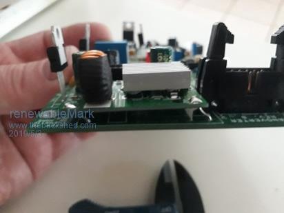 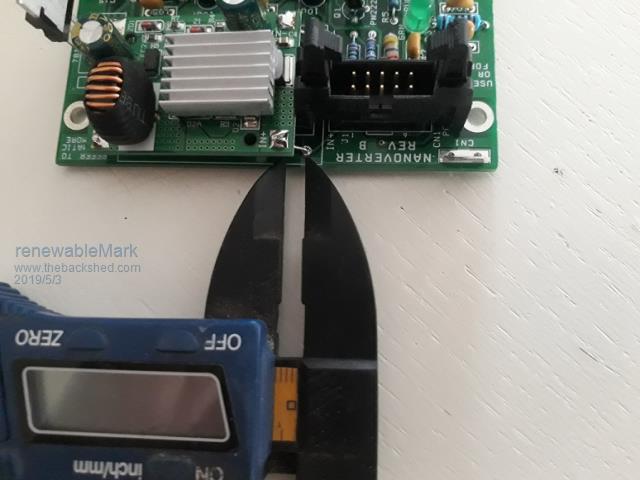 Cheers Caveman Mark Off grid eastern Melb |
||||
| noneyabussiness Guru Joined: 31/07/2017 Location: AustraliaPosts: 506 |
 Std 10 pin socket doesn't need any mods I think it works !! |
||||
| tinyt Guru Joined: 12/11/2017 Location: United StatesPosts: 431 |
OK here is the updated file. 2019-05-04_025342_Nanoverter_C_Gerbers_Others.zip. The change in distance between J1 and U8 is 4.57 mm. Had to move J1 closer to the edge to clear the mounting hole. I also had to move up U8 and U7. I hope it is enough for a latching type connector. 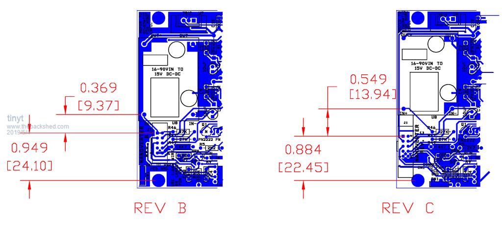 Silkscreen for D17 and D18 are also changed and also the scr reset. |
||||
| renewableMark Guru Joined: 09/12/2017 Location: AustraliaPosts: 1678 |
Big thanks mate. Cheers Caveman Mark Off grid eastern Melb |
||||
| tinyt Guru Joined: 12/11/2017 Location: United StatesPosts: 431 |
WHOOPS! Don't use the rev C gerbers. Big mistake. When I moved J1, and routed manually, the 2HO trace shorts to gnd. Will re-check carefully and upload rev D. Sorry, I really am too old for this. |
||||
| renewableMark Guru Joined: 09/12/2017 Location: AustraliaPosts: 1678 |
Moving bits around to fit the clamp connector really isn't needed mate, Power supply can fit easy enough with bent legs. Might be safer to revert back to the old file and just sort out the silkscreen and scr alterations. Up to you mate. Cheers Caveman Mark Off grid eastern Melb |
||||
| tinyt Guru Joined: 12/11/2017 Location: United StatesPosts: 431 |
I still want to do this. It is up to you if you want to use the rev B files. It is only the J1, U8 and U7 connections that I need to check carefully, I will also go over the scr connection to make sure. In that picture with dimensions I uploaded, you can see the mistake, it was the untouched trace that gets shorted to the IN- pin of the DC-DC (U8) when I moved U8. And it just so happened that the IN- pin pad landed at the corner of the trace. So visually it looks like the connection is intentional. I am going to work on this tomorrow to rest my tired eyes today. Just got home from work. Too tired now. |
||||
| tinyt Guru Joined: 12/11/2017 Location: United StatesPosts: 431 |
Here is rev D. 2019-05-05_081432_Nanoverter_D_Gerbers_Others.zip I checked it several times, hopefully I did not miss anything. I have also include the orcad layout .max file in case some of you can import it to your pcb software and will spend the time to check it. Shown below is the area of the pcb with the major changes. It does not have yet the copper pour so that the copper traces can be seen easily. In case you want to check it this way. 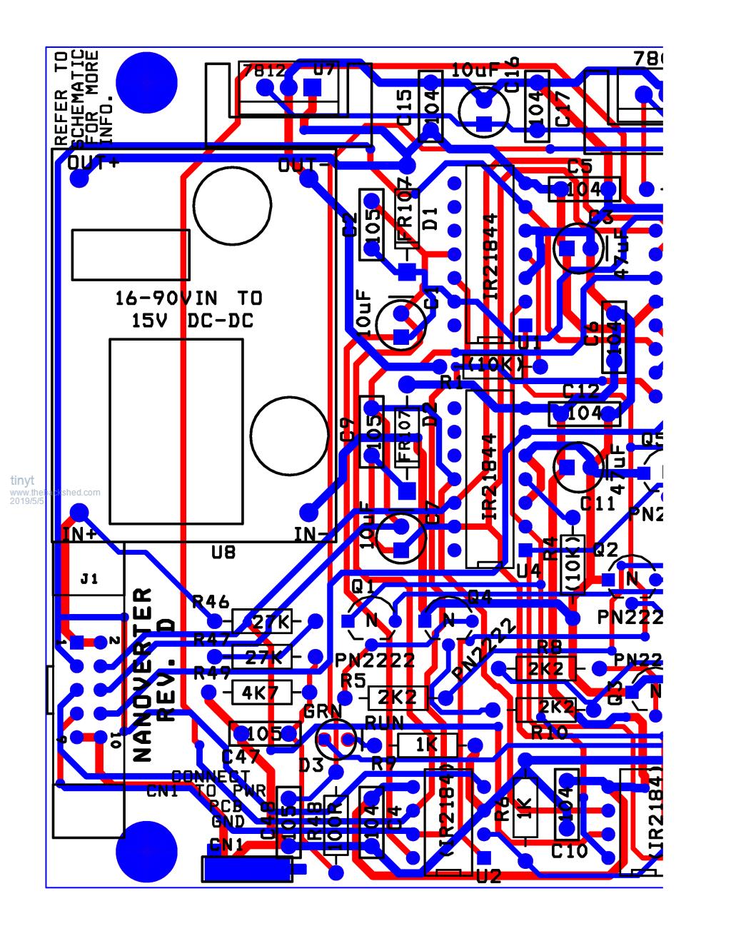 And here is the same area with the copper pour applied. 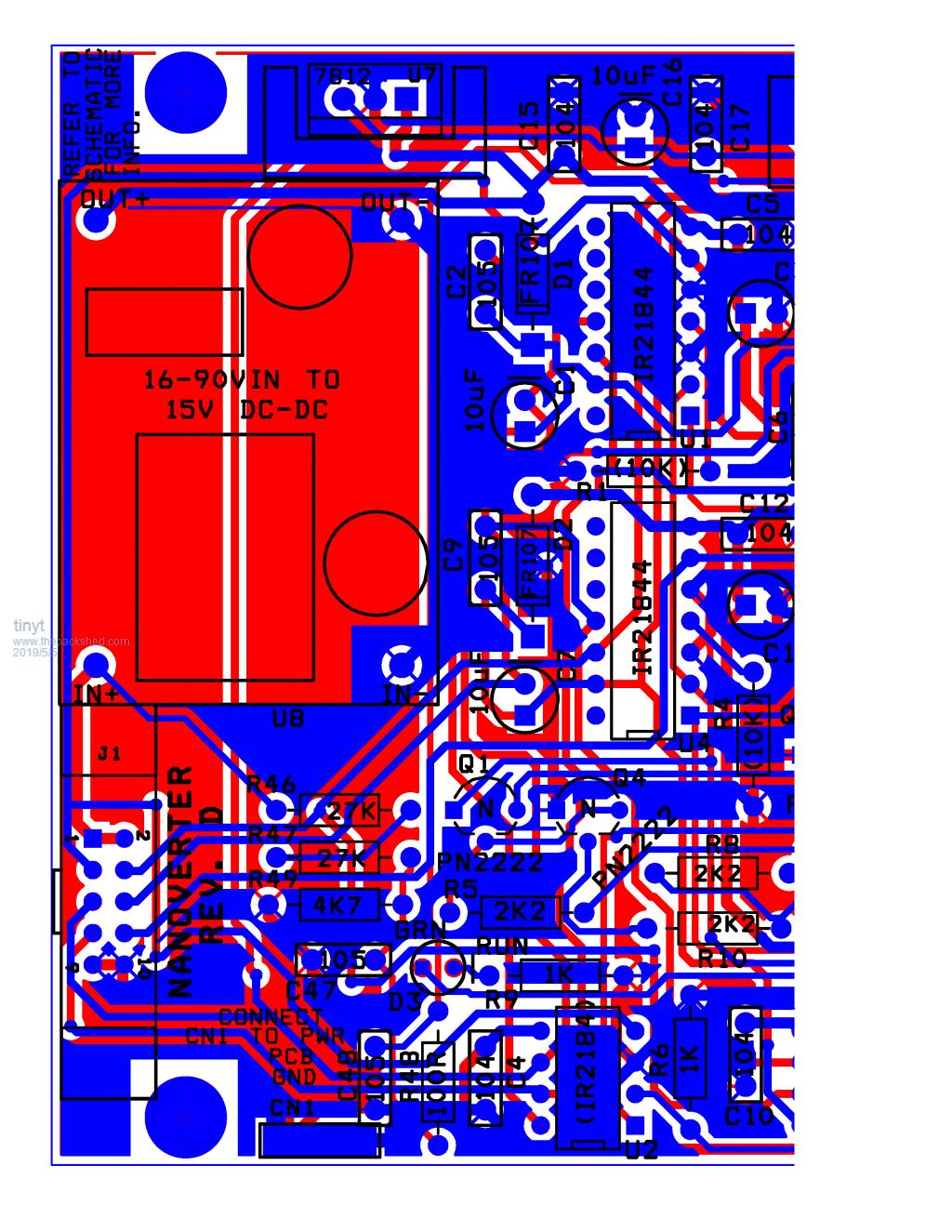 I have added the scr area (no copper pour yet) below. 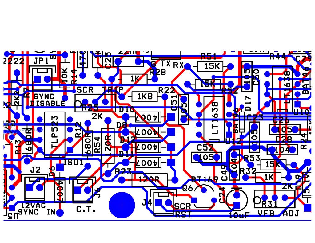 |
||||
| hugocamaras Newbie Joined: 12/04/2019 Location: BrazilPosts: 24 |
Good job! I am so thankful for the hard work! This project provides the possibility for anyone to get out of the energy grid economically and open source friendly. Special thanks: Poida (project and embedded software), Tinyt (electronic schematics and PCB's) and all others who have contributed so far.   |
||||
| poida Guru Joined: 02/02/2017 Location: AustraliaPosts: 1388 |
I was wondering about the utility of the Powerjack LF "6000W" I have here. I don't use it much any more. Whenever I run it, it seems to need the cooling fan a lot, even when at idle. The idle power has been reduced thanks to fitting a good ferrite choke. It's still about 23W idle at 53V. I have relocated it's toroid to stand vertically, to permit cooling airflow through and around it's entirety. This was a near useless attempt to reduce the time the fan stays on. But it's built strong. I wondered since I have a Mad control board (for a little while yet) and the nanoverter, both having compatible control signals, how would these two controller boards go driving the Powerjack power board? I pulled the PJ powerboard out and ran it at 28V DC supply. I connected the powerboard to the bench test toroid, which includes a 47uH choke and a 10uF cap on the secondary, set at 230V AC. When driving the PJ power board, the Madness controller (IR2110 gate drive ICs) needed 1.13 A at idle. (31.6W) Also, the Madness controller, thanks to the EG8010, had the test toroid making a bit of high frequency audible noise. Of course it was still set to 60Hz output. 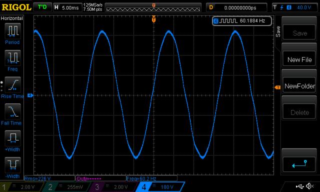 The nanoverter, using IR21844 drive ICs and 15V gate drive amplitude needed only 0.46A at idle. (12.9W) It runs at 50Hz. And it's driving of the PJ board was very quiet. 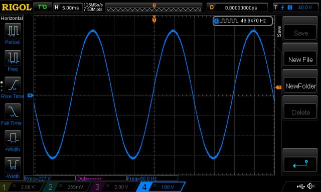 After that, I wondered how the single HY4008 bridge Madness power board compares to the PJ. Mad controller : 0.40A (11.2W) and quiet. Nanoverter: 0.38A (10.6W) and quiet. The same current draw. Different AC output frequencies. I wanted also to prove a Mad control board can run a PJ powerboard. Ben and Amber want to run their PJ using this particular Mad control board. I thought it best to see if it works or not against a PJ board. It makes you wonder if they'd be better off using a nanoverter to drive the PJ power board. These tests negated any advantages brought by the special gate drive circuit Powerjack have on the PJ control board. When running the reassembled PJ, at 54V, needed only 0.43A (23W) wronger than a phone book full of wrong phone numbers |
||||
| renewableMark Guru Joined: 09/12/2017 Location: AustraliaPosts: 1678 |
Ahhhh, remember a few pages back when I said my battery volts was consistently higher in the morning compared to when I used to run the Mad controller. The nano seems to run more efficiently. Also Poida, you should have a few spare 8010 boards there, you can test it with a comparable 50hz Cheers Caveman Mark Off grid eastern Melb |
||||
| poida Guru Joined: 02/02/2017 Location: AustraliaPosts: 1388 |
I ran the PJ powerboard at 28V DC using the Mad controller, with 50Hz EG8010. 1.07A at 28.1V = 30.0W I was sure the change from 50 to 60Hz in this case would not be significant. It was not. This is thanks to the fact the toroid is not even close to saturation at 230V on it's secondary at 50 and 60Hz. In fact, I have shown here that saturation begins at about 40Hz. (slower frequency means more time pumping current into the core.) wronger than a phone book full of wrong phone numbers |
||||
| poida Guru Joined: 02/02/2017 Location: AustraliaPosts: 1388 |
Tinyt, how are things gong with the pcb files? No hurry, I want to check with you before I take the latest files you have posted here and engage the pcb manufacturer. wronger than a phone book full of wrong phone numbers |
||||
| poida Guru Joined: 02/02/2017 Location: AustraliaPosts: 1388 |
PCB order summary: 1 x for Mark, 2 x for Noneya, 2 x johnmc, 2 for someone else, 2 for Ben&Amber. total of 9 + my 3 or 4 = 12 to order. Anybody else want some? I think it's nearly time to order. wronger than a phone book full of wrong phone numbers |
||||
| renewableMark Guru Joined: 09/12/2017 Location: AustraliaPosts: 1678 |
I'll grab another two, =total of three for me. That makes 14, you need one more to get the 15 bracket (they place orders in increments of 5) Cheers Caveman Mark Off grid eastern Melb |
||||
