
|
|
Forum Index : Microcontroller and PC projects : PWM
| Author | Message | ||||
lew247 Guru Joined: 23/12/2015 Location: United KingdomPosts: 1709 |
I want to control an AC 2 wire motor that uses very little current, microamps from a Pic I have successfully done this by having it connected to 2 pins and doing the following PIN(7) = 1 PIN(8) = 0 pause 75 PIN(7) = 0 PIN(8)= 1 pause 75 I've been told it will work better if controlled using PWM and it can be done from the micromite but despite reading everything I can about PWM and reading the manual I cannot get my head around how it works Is it possible to do with? and any suggestions how? it's a clock motor and it has to get a positive pulse, pause and then a negative pulse for the same period as the positive pulse to move one step |
||||
| BrianP Senior Member Joined: 30/03/2017 Location: AustraliaPosts: 292 |
Hi Lew I think your present method is probably the better - PWM has a smooth average output useful for continuously varying motor speed for more conventional motor types. Your clock motor speed is controlled by the frequency of the pulses you send it. So it's behaving like a stepper motor (sort of)... What is the origin of this motor? It sounds like a battery operated clock motor (1.5 volt). Also, in what way does it need to work better? Cheers B |
||||
| PeterB Guru Joined: 05/02/2015 Location: AustraliaPosts: 669 |
G'Day. It could be done using a PWM signal to drive something like a 74HC74 flip flop to give a bipolar signal. Then your micro would have an easier life but at the expense of extra hardware. Peter |
||||
Chopperp Guru Joined: 03/01/2018 Location: AustraliaPosts: 1126 |
Hi, I think this should work. I've used the NOT command to change pin states before on the 'Mites. PIN(7) will change state every call of SETTICK & PIN(8) will be set to the opposite state of pin(7) Using SETTICK frees up the 'Mite for other stuff. SETTICK 75, Clock_pulse, 1 SUB Clock_Pulse PIN(7) = NOT PIN(7) 'change the state of pin(7) PIN(8) = NOT PIN(7) 'set PIN(8) to opposite of pin(7) END SUB Brian ChopperP |
||||
LadyN Guru Joined: 26/01/2019 Location: United StatesPosts: 408 |
OK. Before you proceed figure out which PWM frequency your DC motor gives the highest torque at. Design the HBridge/switch around that PWM frequency. My first PIC18 controlled HBridge worked great in simulation until I built it on a board and it was able to barely turn the DC motor because it worked at 100kHz. I had to get it down to 17kHz for it to give the highest torque so it could be regulated properly with DC 3% - 90%. EDIT: I noticed you use an AC motor. No experience with those. Keeping this post around for use later, hope it's ok. |
||||
| lew247 Guru Joined: 23/12/2015 Location: United KingdomPosts: 1709 |
Sorry I actually made a mistake it's actually a DC motor, it's a single phase stepping motor that needs a positive pulse to move one step then a negative to move the next step and so on It is a watch motor* |
||||
| PeterB Guru Joined: 05/02/2015 Location: AustraliaPosts: 669 |
I think you should think of this motor as an AC motor. It is excited by a positive voltage followed by a negative voltage i.e. a simple A.C. waveform although, in modern digital systems, sinusoidal waveforms are being replaced by steps. The 2 options you have been given should do what you want without loading up the micro. Good luck. Peter |
||||
| LadyN Guru Joined: 26/01/2019 Location: United StatesPosts: 408 |
|
||||
| PeterB Guru Joined: 05/02/2015 Location: AustraliaPosts: 669 |
I'll bet my boots it's a reluctance motor. Peter  |
||||
| BrianP Senior Member Joined: 30/03/2017 Location: AustraliaPosts: 292 |
Lew - out of curiosity what are you wanting to do with this motor? If it's a watch motor as you say then it will have VERY limited torque. As it draws microamps (or even milliamps) it's not likely to strain your Micromite unduly especially as the outputs are only pulsed. I still think your original method of driving it is the best method (refer my earlier post). B |
||||
TassyJim Guru Joined: 07/08/2011 Location: AustraliaPosts: 6538 |
In simple terms, Lew is replacing the control board on an analogue clock with a more accurate time source. He plans to have it auto correct with power failures and auto adjust for daylight saving. Jim VK7JH MMedit |
||||
| PeterB Guru Joined: 05/02/2015 Location: AustraliaPosts: 669 |
G'Day GrianP His method works but the micro spends a lot of time doing delays etc. If he wants to do other things he may run into timing problems. My method (ahem) is the best (ahem ehem) because PWM runs in the background and does not interfere with the micro but it does mean extra hardware. So it comes down to what is required. I hope I'm correct in saying that it is a reluctance motor. Peter Edit You sneaked one in there Jim. How do you know that? It looks like there will be quite some processing to speed up the motor to correct time after it has been derived, GPS? But it does sound like fun. P |
||||
| TassyJim Guru Joined: 07/08/2011 Location: AustraliaPosts: 6538 |
Lew asked me to help him with the 47L04 EEPROM chip https://www.thebackshed.com/forum/forum_posts.asp?TID=11033&PN=2 He told me why. I don't think I have a suitable clock module but I must have a rummage in the shed... Jim VK7JH MMedit |
||||
| BrianP Senior Member Joined: 30/03/2017 Location: AustraliaPosts: 292 |
@PeterB - good point (which is why I asked what the intended use was). Would not he be better off then using PULSE instead of PWM? The pulse subroutine could be called from a 1 second interrupt, which shouldn't upset any existing program. Any correction necessary could be either to add an extra pulse occasionally or to turn off pulsing momentarily if needed to slow down. All the clock motors I have ever seen as Lew has described work on alternate polarity 1 second pulses, although there are some than run a lot faster to provide a smooth (continuous) operation of the second hand. Either way the pulse method should be able to cope? Anyway just my 2c worth... B |
||||
| PeterB Guru Joined: 05/02/2015 Location: AustraliaPosts: 669 |
Yep. I think we need England to wake up. C'mon Lew, wake up!  Peter |
||||
| lew247 Guru Joined: 23/12/2015 Location: United KingdomPosts: 1709 |
Sorry The time difference is annoying at times, and I am jealous of your weather down under it's snowing here now It's an analog clock that I'm running from a Pi Zero W and I've made a slight change in the Pi code to get proper NTP time from my local NTP timeservers every 15 minutes so the time is always exact without any fancy code in the MM The issue I had was moving the hands properly, the motor moves 1 pulse (second) by applying a positive voltage pausing then a negative voltage to move the next second It was driving me potty because it was moving 2 seconds for every real second until I realised that I was actually telling it to do exactly that - stupid mistake! It's working perfectly now and I've had it running for a few days with no errors Thanks Brian for your "NOT" idea, it actually reading that when I realised that I was telling the code to move 2 seconds for every real second. I've designed the board so it also has a temp sensor and a connection for an E-Ink display to display the Day and Date and temperature (but doesn't have to be used) The board below shows a button to move the hands manually if you ever need to but I've removed it in the final PCB I'm using an Sram that HAS to be set to "00000" when the board is first powered up, and then the clock code loaded Move the hands manually using the wheel on the back of most clock modules or moving the minute hand only to 12:00:00 Power up and it will start ticking fast till it catches up with the current time and then once per second If there is a power cut then the Sram writes to it's internal Eeprom and this is the position of the hands in seconds. Once power is reapplied, this figures is transferred back to the Sram, read and then the hands will move fast until it catches back up to the correct time. I haven't worked on the E-Ink code yet as I blew my first display by using 5V when the maximum voltage is 4V Hopefully I'll be able to get it working tomorrow when I'm off work next The board fits perfectly on top of a Pi Zero W and is a tiny bit wider to allow the pinouts for the E-Ink to be shown It also has a "heartbeat" LED so you can see it working I've used a 2.54mm pinout for the DS18B20 so it can be mounted off the board and anywhere on the clock away from any heat 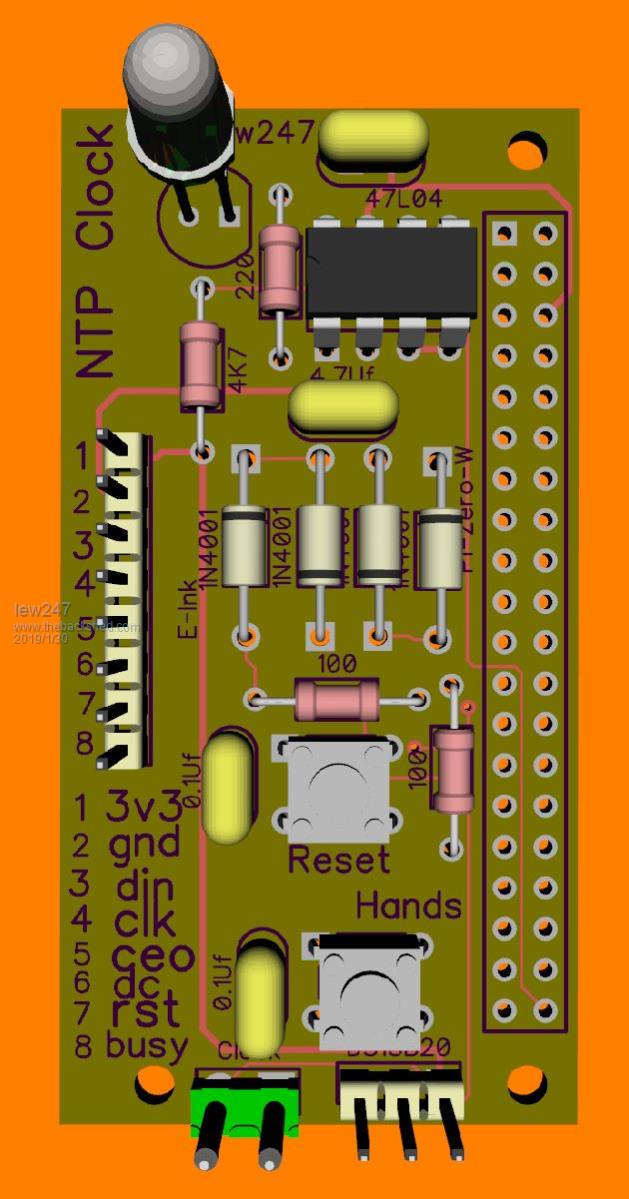 The reset button isn't really needed but it's there in case someone really messes up the hands while the clock is running, it will reset the Pi totally, the power can then be removed, the Sram written with "00000" again and then the MM code loaded after moving the hands to 12:00:00 again Once I'm happy it all works ok and no issues, I'm going to use a different chip such as ATTINY85V-10SH with an Esp8266 or possibly a receiver to pick up the MSF/DCF/Wghatever radio signal This would allow it to be run from an "AA" for at least a year or more, or even a "C" for a few years The other option is once Matherp is happy with his Armite L4 code to use that with a receiver which although won't be such low power as the other chip, it should still allow the clock to run for a very long time on battery And the E-Ink display can always show the battery voltage as well if wanted so it will be easy to see when it needs changing |
||||
| PeterB Guru Joined: 05/02/2015 Location: AustraliaPosts: 669 |
Don't apologize and don't be too jealous of our weather. 38C today, 47.5 last week but 28 tomorrow. Palcal has been talking about something called rain???. I have no idea what he is talking about.  So all your problems are solved? Peter |
||||
| The Back Shed's forum code is written, and hosted, in Australia. | © JAQ Software 2026 |
