
|
|
Forum Index : Microcontroller and PC projects : Picromite Analogue Clock
| Author | Message | ||||
lew247 Guru Joined: 23/12/2015 Location: United KingdomPosts: 1709 |
I've been working on an Analogue clock module for a few weeks and I'm finally happy with it The clock works by using a normal cheap quartz clock module, opening it up and cutting the track that goes to the coil, it's important you cut both ends Then solder a short wire to the 2 solder points that only are connected to the coil The board connects an a Raspberry Pi Zero W which uses Raspbian, I've modified the code very slightly so it uses proper NTP time and gets the time updates from my local UK NTP servers and updates the time every 15 minutes so it's always correct to under a second with no RTC or anything needed. It also has an Sram module that can be written to as many times as needed and if the power is lost it writes the last value it has stored into it's internal Eeprom whicb is then read back once power is restored The time instead of using hours minutes and seconds are processes as seconds only, with 0 being midnight or 12:00:00 and counting up once every second This value is stored in the Sram every second so the Picromite always knows the position of the hands as a value in seconds of the day When the module is first powered up it has to have a small program sent to it to set the Sram value to "00000" Then the clock code is loaded Move the hands to exactly 12:00:00 and when your ready tell it to run The clock gets the current time as seconds and knows how many steps to move the hands to get to the current time, and it moves pretty quickly to get there. Once it's at the correct time it then pulses the hands once every second Every time the hands move 1 second the counter for the Sram is increased by 1 until midday or midnight when it's reset to zero If the power is lost, when it's powered up again the Sram is read, the Picromite knows the position of the hands, checks the current time and moves the hands to the correct time and then ticks once a second If Daylight time goes forward the clock knows the hands need moving fast to catch up If it goes back an hour the hands advance fast till midnight the Sram counter is reset to Zero and then the clock carries on to catch up with the correct time There is a reset button on the board in case something major happens and the Picromite needs rebooting Such as the clock being taken off a wall by a child and the hands moved while still powered up but the chance of this is very slim. If this every happens simple press it then remove the power from the board, move the hands manually by the wheel on the back of the clock to 12:00:00 and then load the Sram program first then the Clock code and it will work as normal I've not needed to do this at all and I've been testing it for a while WW said about putting a button on the board to move the hands if needed if it every crashes but although the board I have now has that button I've removed it from the circuit as I can't see it being needed There is a connection for one of the waterproof DS18B20's on the board this isn't needed I only included it because IF I can ever get an E-Ink display working with the Picromite then I'll use it to display the temp every 5 minutes and the day and date can be updated once a day I don't think the E-Ink display works with the Picromite though as I haven't been able to get it working at all My end goal is to use one of the Arm very low power modules once they are working good enough and it will then run on battery power for over a year You can see it working here to catch up with the correct time 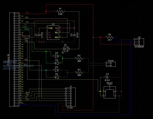 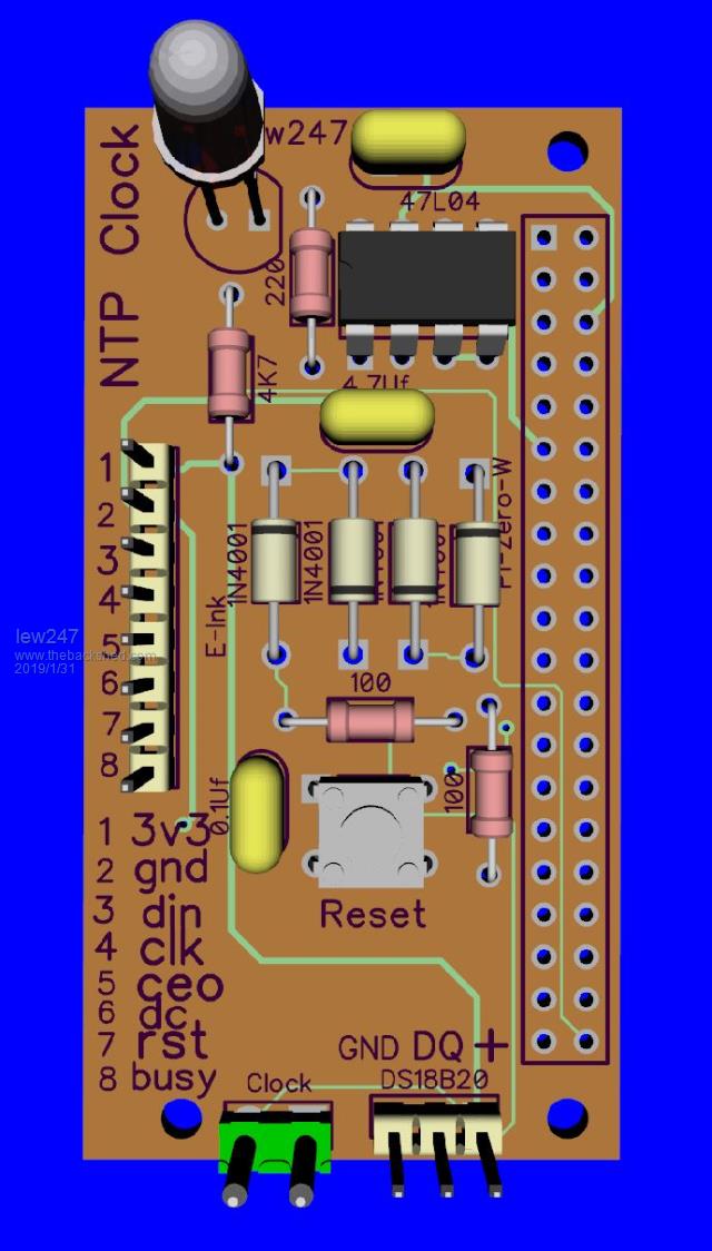 |
||||
| WhiteWizzard Guru Joined: 05/04/2013 Location: United KingdomPosts: 2991 |
Absolutely BRILLIANT write up of your Clock project. Great work!  |
||||
| viscomjim Guru Joined: 08/01/2014 Location: United StatesPosts: 925 |
lew247, EXCELLENT PROJECT!!! I would be interested in your code if you are willing to share. I also fully understand if you don't. Good job on this one and very creative use of mmbasic. |
||||
| lew247 Guru Joined: 23/12/2015 Location: United KingdomPosts: 1709 |
Code enclosed I'll update with the E-Ink code as well once I get the display working if anyone is interested 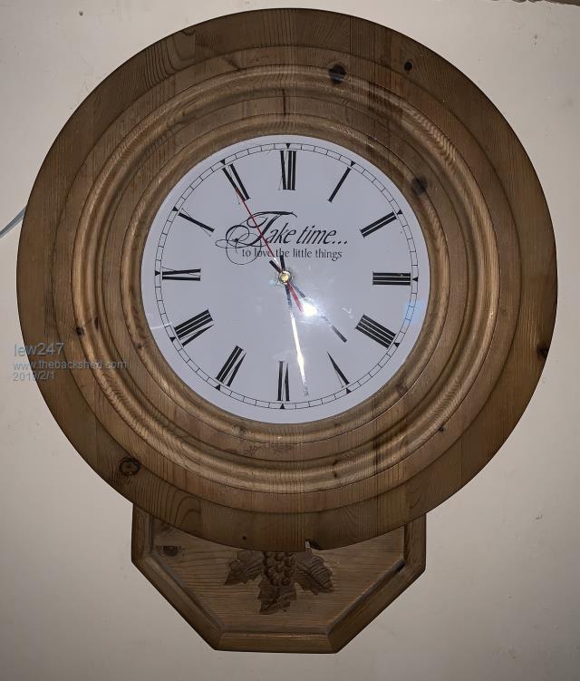 It's Still working, even after killing the power several times YouTube Link 2019-02-01_021056_Clock.zip 2019-02-01_022636_Clock-Gerbers.zip This is how I changed the time on the Pi Zero W to proper NTP time On Raspbial Stretch it now uses systemd-timesync service instead of full NTP time [quote]To use proper NTP servers in your location do the following: sudo apt-get install ntp sudo systemctl stop systemd-timesyncd sudo systemctl disable systemd-timesyncd sudo /etc/init.d/ntp stop sudo /etc/init.d/ntp start sudo nano /etc/ntp.conf And find lines starting with "server". Replace that lines for lines with servers with your local servers (mine are) server 0.uk.pool.ntp.org iburst server 1.uk.pool.ntp.org iburst server 2.uk.pool.ntp.org iburst server 3.uk.pool.ntp.org iburst sudo /etc/init.d/ntp restart restarts the NTP service ntpq -pn - checks if NTP is set properly and syncronising You'll get an output like this if it is ntpq -pn remote refid st t when poll reach delay offset jitter ============================================================================== 134.0.16.1 195.66.241.10 2 u 6 64 1 18.089 -0.101 0.002 85.199.214.100 .GPS. 1 u 4 64 1 19.906 0.086 0.002 2a03:b980:123:1 195.66.241.10 2 u 7 64 1 18.002 -0.966 0.002 95.215.175.2 192.146.137.13 3 u 7 64 1 20.294 0.468 0.002 Type timedatectl - This confirms if NTP is setup properly and running and synchronises You'll get an output similar to this if it is Local time: Fri 2018-12-14 09:00:49 GMT Universal time: Fri 2018-12-14 09:00:49 UTC RTC time: n/a Time zone: Europe/London (GMT, +0000) Network time on: no NTP synchronized: yes RTC in local TZ: no ****IF you want you can then use this NTP time to syncronise other devices in your network*** When RPi has synchronized its time, you can set it to pass this time information to devices in your local network. You only have to open configuration file of ntp daemon. nano /etc/ntp.conf And add a string that describes the hosts which requests will be answered. restrict 192.168.1.0 mask 255.255.255.0 And also add this 2 lines. They will enable sending of broadcasts and multicasts containing time information for devices which accept them (Cisco, Juniper...)). Change first address in bold to broadcast address of your LAN. Do not change multicast address 224.0.1.1 since this addreess is assigned to NTP service by IANA and some network devices join this multicast group automatically. broadcast 192.168.1.255 broadcast 224.0.1.1 Now close the configuration file (CTRL+X...) and save changes (...press "y" and Enter). Last step is to restart ntp daemon with: /etc/init.d/ntp restart From now you can configure machines in local network to synchronize its time to RPi. I would suggest you set your Pi with a Static IP address to do this[/quote] |
||||
| lew247 Guru Joined: 23/12/2015 Location: United KingdomPosts: 1709 |
I just realised one thing You do not have to move the hands should the clock hands get physically moved, OR if when you first set it up you find you have the hands positioned slightly wrong. Just work out the number of seconds the hands are at when they stopped. An exammple 7:10:01 is 7 hours = 60 seconds X 60 minutes * 7 hours = 25520 10 minutes = 60 seconds * 10 minutes = 600 + 1 second = 25801 seconds Just modify the Sram.bas file so line 10 says [quote] r = writeDATA(10,"25920")[/quote} That writes the current position of the hands to the Sram instead of "00000" which would mean they are at 12:00:00 Then run the Clock.bas program and the clock will catch up and carry on |
||||
Grogster Admin Group Joined: 31/12/2012 Location: New ZealandPosts: 9975 |
Beautiful work. Smoke makes things work. When the smoke gets out, it stops! |
||||
disco4now Guru Joined: 18/12/2014 Location: AustraliaPosts: 1127 |
Nice work. Gerry F4 H7FotSF4xGT |
||||
Chopperp Guru Joined: 03/01/2018 Location: AustraliaPosts: 1126 |
Agreed. Great to see those hands moving so quickly with that bit of motor drive code working.  (Understand much better as to what you were trying to do  ) )Brian ChopperP |
||||
palcal Guru Joined: 12/10/2011 Location: AustraliaPosts: 2039 |
I agree, brilliant. Unfortunately we don't have any such time signals here that I know of. I did make the Analogue GPS clock from Geoff's site and that works well. "It is better to be ignorant and ask a stupid question than to be plain Stupid and not ask at all" |
||||
TassyJim Guru Joined: 07/08/2011 Location: AustraliaPosts: 6538 |
Lew is using the Internet time (which we can all get) in this case but he has looked at the European RF time signals. We can't get them here. You could combine using the GPS signals and Lew's idea for recovering from power failure. I do know it's coffee time without having to resort to high tech stuff. I can smell the beans. Jim VK7JH MMedit |
||||
| lew247 Guru Joined: 23/12/2015 Location: United KingdomPosts: 1709 |
This clock uses NTP time from the internet only to keep it accurate The main difference between this and Geoff's GPS clock is this one remembers where the hands are if there is a power loss and will automatically catch up to the correct time once power is restored |
||||
| lew247 Guru Joined: 23/12/2015 Location: United KingdomPosts: 1709 |
***I made an error on the board which is why the E-Enk display wasn't working*** I've also modified the code Now the hands can be at any position when power is applied or if the hands get moved manually by accident it doesn't matter Run the file "Sram.bas" It asks you for the position of the hands and then sets the Sram to the correct seconds of the day value It doesn't matter if this is the first time you power the module up or not as long as you input the exact position of the hands Then run "Clock.bas" and the hands will move fast till it gets to the correct time and then tick once a second keeping the time perfectly 2019-02-02_014006_PiClock.zip Diptrace files also attached in case anyone is interested 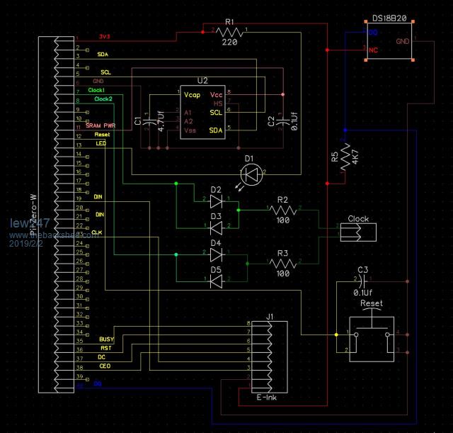 Code to tell the Sram the position of the hands: [code] I2C OPEN 400,1000 CONST EERAMcr=&h18' address of 47x04/47x16 control register with A0=0 and A1=0 CONST SRAMcb=&h50' address of 47x04/47x16 data register forSRAM with A0=0 and A1=0 CONST COMMANDreg=&h55 ' address of 47x04/47x16 command register CONST STATUSreg=&h00 ' address of 47x04/47x16 status register CONST S_store=&h33 ' these are the two command register commands CONST S_recall=&hdd CONST SRAMsize = 512 ' size of 47x04, use 512 for 47x04 r = setup() ' we only have to do this once for each chip r = writeDATA(10,"00000") z$ = readDATA$(10,5) ' 5 bytes starting at address 10 (any address will do) print "Sram Check "+z$ seconds=Val(Right$(Time$,2)) mins=Val(Mid$(Time$,4,2)) hours=Val(Left$(Time$,2)) print "Enter Hours" input hours if hours > 12 then print "ERROR - please run this program again and enter the correct hour" end end if print "Enter mins" input mins if mins > 59 then print "ERROR - please run this program again and enter the correct minute" end end if print "Enter seconds" input seconds if seconds > 59 then print "ERROR - please run this program again and enter the correct second" end end if if hours = 12 then hours = 0 secs = (hours * 60 * 60) + (mins * 60) + seconds print secs, "Sram Value" r = writeDATA(10,str$(secs,5,0,"0")) 'Update Sram z$ = readDATA$(10,5) ' 5 bytes starting at address 10 (any address will do) print "Sram Check "+z$ '****************Sram Functions****************** FUNCTION setup() x = readstatus() ' get the current status register x = x OR &b10 ' set bit 2 leaving the rest alone PRINT BIN$(x,8) r = writeCMD(STATUSreg,x) ' set autostore r = readstatus() PRINT BIN$(r,8) END FUNCTION FUNCTION writeDATA(addr,D$) ' write string D$ to EERAM starting at addr LOCAL L addr = addr MOD SRAMsize ' keep address within chip capacity d$ = CHR$(addr\256)+CHR$(addr MOD 256)+D$ L = LEN(D$) ON ERROR SKIP 1 I2C WRITE SRAMcb,0,L,D$ END FUNCTION FUNCTION readDATA$(addr,L) ' read string from EERAM starting at addr, L bytes LOCAL D$ addr = addr MOD SRAMsize ' keep address within chip capacity ON ERROR SKIP 1 I2C WRITE SRAMcb,1,2,addr\256,addr MOD 256 'Reset memory pointer to addr I2C READ SRAMcb,0,L,D$ readDATA$ = D$ END FUNCTION FUNCTION writeCMD(reg,EERAMcmd) 'write command to the command or status register ON ERROR SKIP 1 I2C WRITE EERAMcr,0,2,reg,EERAMcmd END FUNCTION FUNCTION readSTATUS() 'read status register LOCAL status ON ERROR SKIP 1 'I2C WRITE EERAMcr,1,2,STATUSreg,0 I2C READ EERAMcr,0,1,status readSTATUS = status END FUNCTION [/code] Clock code: [code]'Analogue clock module driver for Pi Zero W which will always have the correct time and can if needed show temp and day/date and battery voltage on an E-Ink display 'Clock works by stripping time into seconds and advances the motor by 1 movement per second 'Sram stores the position of the hands and if power is ever lost hands will automatically go to the correct time once power is restored 'Sram has capacitor with enough capaciity to write value to internal Eeprom once power is lost 'Thanks to TassyJim for his help in getting the 47L04 working Option explicit I2C OPEN 400,1000 'used later after the E-Ink display is set uprun CONST EERAMcr=&h18' address of 47x04/47x16 control register with A0=0 and A1=0 CONST SRAMcb=&h50' address of 47x04/47x16 data register forSRAM with A0=0 and A1=0 CONST COMMANDreg=&h55 ' address of 47x04/47x16 command register CONST STATUSreg=&h00 ' address of 47x04/47x16 status register CONST S_store=&h33 ' these are the two command register commands CONST S_recall=&hdd CONST SRAMsize = 512 ' size of 47x04, use 512 for 47x04 DIM hours, mins,seconds,secs,secs2,secs3,g,h,c,b,a,l,r,w,x,z$,t$,d$,temp SETPIN 12,INTL,reset1,PULLUP ' Reset button SetPin 7, dout 'Motor pulse 1 SetPin 8, dout 'Motor pulse 2 setpin 13, DOUT 'Hearthbeat LED PIN(13) = 1 'Led off z$ = readDATA$(10,5) 'read 5 bytes starting at address 10 - where the hands were on Power Loss print z$ secs2 = VAL(z$,"0") 'Position of hands on Power Up PIN(7) = 1 PIN(8) = 0 do secs3 = Val(Right$(Time$,2)) secs=(Val(Left$(Time$,2)) Mod 12) * 3600 + Val(Mid$(Time$,4,2)) * 60 + Val(Right$(Time$,2)) ' total clock's seconds past midnight if secs > secs2 then 'New second hand need moving motor1 end if if secs2 = 7199 and secs = 3600 then 'time has gone back 1 hour MOTORBACK end if if secs3 = 31 or secs3 = 01 then ' Print Temperature (When E-Ink is connected this can be displayed) PRINT STR$(tempr(40))"`C", "Temperature" 'display the temperature every 30 seconds end if if secs = 0 then 'time is 00:00 we need to reset the secs2 counter to zero and pause 1 second motor1 secs2 = 0 r = writeDATA(10,"00000") 'Update Sram pause 1000 end if if secs = 43200 then 'time is 12:00 we need to reset the secs2 counter to zero and pause 1 second motor1 secs2 = 0 r = writeDATA(10,str$(secs2)) 'Update Sram pause 1000 end if loop end SUB motor1 'pulse clock motor once every second - PIN(7) = NOT PIN(7) 'change the state of pin(7) PIN(8) = NOT PIN(7) 'set PIN(8) to opposite of pin(7) PIN(13) = 0 'led on pause 50 'so the motor will actually move - too short a delay and it will miss steps PIN(13) = 1 'led off secs2 = secs2 +1 'advance value stored in Sram to = number of seconds +1 r = writeDATA(10,str$(secs2,5,0,"0")) 'Update Sram print time$ 'Test to make sure it's working - delete when not needed print secs2 " secs2" END SUB SUB motorback ' move clock back one hour becuuse of daylight change time for g = 7199 to 43200 'number of steps to get hands back to 12:00:00 print secs, "Time has gone back an hour - catching up with the correct time" 'so we know the number of steps to clock hands have to move r = writeDATA(10,str$(secs2,5,0,"0")) 'Update Sram PIN(7) = NOT PIN(7) 'change the state of pin(7) PIN(8) = NOT PIN(7) 'set PIN(8) to opposite of pin(7) PIN(13) = 0 'led on pause 50 'so the motor will actually move - too short a delay and it will miss steps PIN(13) = 1 'Led off secs2 = secs2 +1 print b, "secs2 - steps to align hands" next g secs2 = 0 'hands will now advance from 12:00:00 to the current time END SUB sub reset1 IF PIN(12) = 0 THEN ' button down secs2 = 0 t$=time$ r = writeDATA(10,str$(secs2,5,0,"0")) 'Update Sram System "sudo reboot" end if '****************Sram Functions****************** FUNCTION setup() x = readstatus() ' get the current status register x = x OR &b10 ' set bit 2 leaving the rest alone PRINT BIN$(x,8) r = writeCMD(STATUSreg,x) ' set autostore r = readstatus() PRINT BIN$(r,8) END FUNCTION FUNCTION writeDATA(addr,D$) ' write string D$ to EERAM starting at addr LOCAL L addr = addr MOD SRAMsize ' keep address within chip capacity d$ = CHR$(addr\256)+CHR$(addr MOD 256)+D$ L = LEN(D$) ON ERROR SKIP 1 I2C WRITE SRAMcb,0,L,D$ END FUNCTION FUNCTION readDATA$(addr,L) ' read string from EERAM starting at addr, L bytes LOCAL D$ addr = addr MOD SRAMsize ' keep address within chip capacity ON ERROR SKIP 1 I2C WRITE SRAMcb,1,2,addr\256,addr MOD 256 'Reset memory pointer to addr I2C READ SRAMcb,0,L,D$ readDATA$ = D$ END FUNCTION FUNCTION writeCMD(reg,EERAMcmd) 'write command to the command or status register ON ERROR SKIP 1 I2C WRITE EERAMcr,0,2,reg,EERAMcmd END FUNCTION FUNCTION readSTATUS() 'read status register LOCAL status ON ERROR SKIP 1 'I2C WRITE EERAMcr,1,2,STATUSreg,0 I2C READ EERAMcr,0,1,status readSTATUS = status END FUNCTION [/code] |
||||
| The Back Shed's forum code is written, and hosted, in Australia. | © JAQ Software 2026 |
