
|
|
Forum Index : Microcontroller and PC projects : Explore-64 version 1E....
| Author | Message | ||||
Grogster Admin Group Joined: 31/12/2012 Location: New ZealandPosts: 9975 |
Hello all.  I have pretty much finished a new E64 design. This one is the same physical size and pinout as all the others, but includes the 1455 USB interface/programmer chip in SOIC, a Winbond W25Q series EEPROM chip for up to 16MB of on-board storage, and an 11A160 UNIO memory device. This is all I could squeeze into the board.  The board is now four-layer, but the per-board price breaks down to about $2.50 per blank four-layer board. ALL LAYERS: 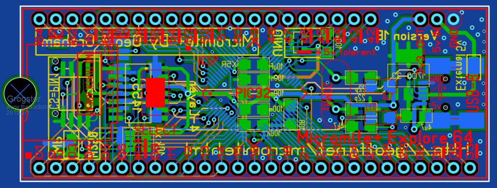 TOP LAYER: 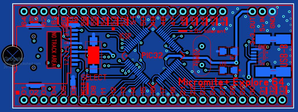 INNER LAYERS: 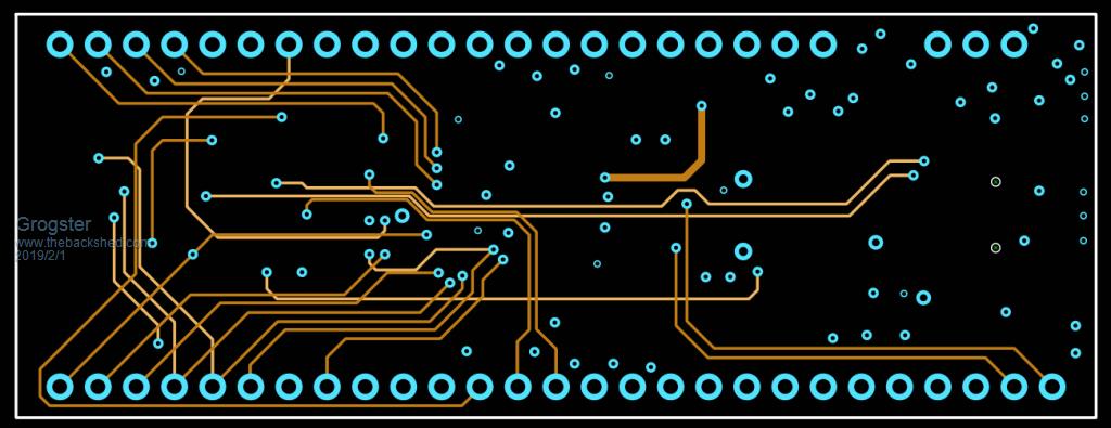 BOTTOM LAYER:  BOTTOM LAYER: (mirrored) 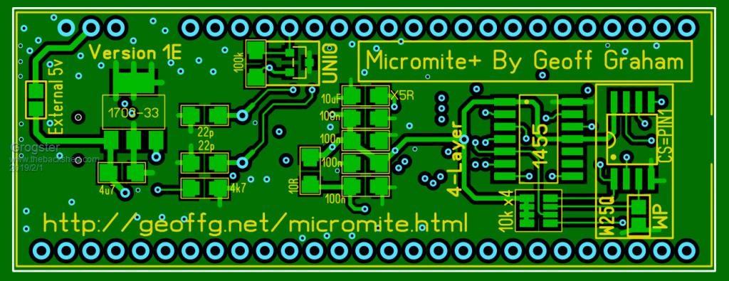 The W25Q SPI EEPROM chips are on SPI2 with the uSD card, but PIN-1 on the E64 is now reserved as the CS line for this chip. The UNIO memory chip is on PIN-46. Either/or/both of these can be installed if wanted - or not. Simply leave them off the board if you don't want to use them. The 1455 interface will be installed by default on any assembled boards. I know you can put the W25Q series of EEPROM chips on the footprint on most parallel LCD modules, but it can be a right pain, if the LCD becomes faulty, and you have to then unsolder and move the chip, whereas here, it is all on-board. This design is effectively closed, to prevent design-by-committee, but if anyone can think of something else I could include - and it would fit, then please let me know here. Smoke makes things work. When the smoke gets out, it stops! |
||||
| viscomjim Guru Joined: 08/01/2014 Location: United StatesPosts: 925 |
I'm starting to get jealous of your PCB routing abilities. 4 layers!!! Nice work sir! |
||||
| JohnL Senior Member Joined: 10/01/2014 Location: SeychellesPosts: 128 |
Dave from EEVblog has just published a video on 2 layer vs 4 layer designs. Importance and benefit of having internal GND and Power planes in 4 layer design. https://www.youtube.com/watch?v=crs_QLuUTyQ Dave is an expert, having worked at Altium designing sophisticated professional boards. |
||||
| Grogster Admin Group Joined: 31/12/2012 Location: New ZealandPosts: 9975 |
I will check out the video. The default standard with a NEW four-layer board, would be to make the internal layers ground and supply - the E28 module is done like that. The E100 is a four-layer board, and both internal layers are signal routing, with ground-plane on top and bottom. Never had any issues with the board at all with respect to noise, and hundreds have now been made. Smoke makes things work. When the smoke gets out, it stops! |
||||
| robert.rozee Guru Joined: 31/12/2012 Location: New ZealandPosts: 2528 |
if you wanted to eliminate the track around the outside edge on one of the middle layers, you could do this: 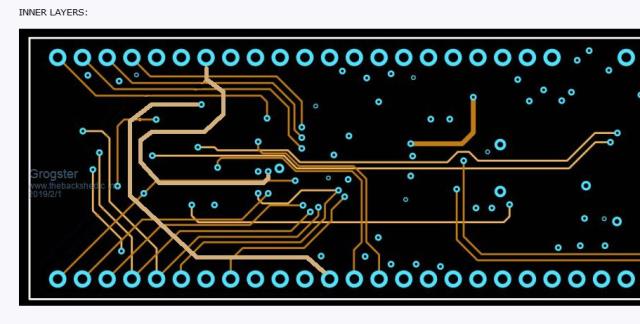 cheers, rob :-) |
||||
| vegipete Guru Joined: 29/01/2013 Location: CanadaPosts: 1179 |
Is that "mounting hole" compatible with an SD card? Does it matter? (Never mind, I see it's only half a hole.) Does the 1455 need to be pre-programmed as there is no (obvious) programming header? Visit Vegipete's *Mite Library for cool programs. |
||||
| Grogster Admin Group Joined: 31/12/2012 Location: New ZealandPosts: 9975 |
@ Rob - good suggestion. I will adopt that. @ vegipete - Yeah, the hole is just an orientation helper. It's kinda like a giant version of the same semi-circle impression you used to get on all IC's and some schematics to indicate the top edge. I just decided to do that, but it really does nothing except help people visually identify the pin-1 end of the module. Weather that really works or not.... Yes, 1455 must be pre-programmed. Any boards I supply will have this chip fitted anyway, so it will be preprogrammed. I made a board a year or so ago and posted it here, where you could program DIL PIC32's and 1455's, and SOIC PIC32's and 1455's via ZIF sockets. Smoke makes things work. When the smoke gets out, it stops! |
||||
| robert.rozee Guru Joined: 31/12/2012 Location: New ZealandPosts: 2528 |
a couple more small suggestions: 1. the track on the top layer that runs between pins 60 and 61, and then along the very edge of the PCB to pin 47 can also be brought away from the edge by either pushing it down to the dark brown middle layer (vias on pins 63/62/61 of the mx470 may need moving a little left/up) and/or to the bottom layer. 2. and lastly the track from pin 2 of the SD socket to pin 12 can be broken with a via just before it passes between pins 6 and 7, then routed to pin 12 on a middle layer. this removes all tracks that pass around the outside edges of the PCB on any layer. tracks on the very edge of PCBs always make me nervous! cheers, rob :-) |
||||
| Grogster Admin Group Joined: 31/12/2012 Location: New ZealandPosts: 9975 |
Here is the E64_1E prototype. 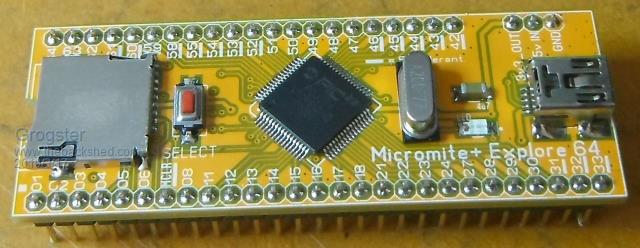 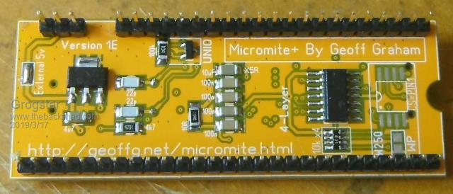 I cannot find the W25Q SPI memory chips I bought, so for this one, it has not been installed. I will add it later when I find the chips. It DOES have the UNIO memory(11AA160) in SOT-23 though, as I have found these chips very useful and they only use one I/O line unlike most other memories. The boards were made with a 'Yellow' soldermask, but it comes back looking much more orange then yellow. Programmed the HEX in fine, initial tests of other things are now under way. One mistake I made was thinking(for some reason) that the 1455 IC's LED was on and only blinked when data was sent. It is the other way around, so this version of the board lacks a power LED. How much of an issue that is, depends on the person. The LED for the 1455 blinks brightly anytime something happens on the console, so it still KINDA doubles as a power LED. Smoke makes things work. When the smoke gets out, it stops! |
||||
| LouisG Senior Member Joined: 19/03/2016 Location: AustraliaPosts: 130 |
Just a small cosmetic point that was immediately spotted, Grogster: The word By on the bottom layer should be written by. Since you are using title case, prepositions are written with a lower case letter. |
||||
| viscomjim Guru Joined: 08/01/2014 Location: United StatesPosts: 925 |
Grogster, your PCB skills are quite amazing. Nice little, yet powerful board there!!! |
||||
| Grogster Admin Group Joined: 31/12/2012 Location: New ZealandPosts: 9975 |
@ LouisG - Thanks. I have corrected that for the next batch of boards. I'm surprised it was not noted before. ALL the E64 boards have had it like that.... @ Jim - Thank you. While I still like the 1D with optional daugherboard, I think this arrangement is neater, and then I don't have to sell the daugherboard separately. And I have squeezed in a few more features. I might change the CS pin for the W25Q SPI chip to something else in the next boards, as I just routed it to the closest pin - pin1 - but that will conflict with anyone wanting to use an SSD1963 LCD panel. The UNIO memory is on pin46, which I don't think conflicts with any of the preset pin things. I will probably move the W25Q CS line to pin12, which does not currently seem to be assigned to anything. Smoke makes things work. When the smoke gets out, it stops! |
||||
| sagt3k Guru Joined: 01/02/2015 Location: ItalyPosts: 313 |
Hi Grogster Very nice job and board in 4layer format. I have 2 question: - Is it always expected for PIC32MX or for MZ? - Regarding the external flash winbond, do You manage LittleFS or FAT/FAT32? Is there a new firmware to handle this new features? Thanks Antonio |
||||
| Grogster Admin Group Joined: 31/12/2012 Location: New ZealandPosts: 9975 |
Hi. 1) PIC32MX only. Does not support the MZ series of chips - unless the MZ's have exactly the same pin-out, which seems unlikely. This is just a revision of the standard E64 module. 2) No. It is only as an on-board memory. LittleFS not supported. I wanted to, but was advised that it is either/or but not both. IE: uSD card or SPI for the FS, but you can't use both. As the uSD has a ton more room on it, and is cheap and easy to use, the SPI chip is as additional memory only, not a FS chip. matherp wrote the LittleFS thing for the MZ series of chips to use an SPI memory as a FS. He might comment here if he thinks it is something that could be made an option for the new board, but I don't expect him to though. There is no space-saving involved, and you get way more space on a uSD card then on the SPI chip, so... No new firmware required. The standard firmware and a couple of Cfunctions/CSubs give you access to the SPI or UNIO memories. The 1455 needs to be pre-programmed before install, as there are no programming pins for this on-board. Smoke makes things work. When the smoke gets out, it stops! |
||||
| The Back Shed's forum code is written, and hosted, in Australia. | © JAQ Software 2026 |
