
|
|
Forum Index : Electronics : Poidas "Inverter Software Control" Topic.
| Author | Message | ||||
| poida Guru Joined: 02/02/2017 Location: AustraliaPosts: 1388 |
I beg to differ, I think it is the magnetising of the toriod core one way, then the other, as the 50 Hz waveform (probably about 90% to saturation) is driven by the inverter. My idle current is 0.39A at 27.3V or approx 10.5W This represents the losses which include but are not limited to - Rds(on) - I2R losses on the primary winding and the choke. - toroid core's hysteresis - powering the nanoverter (about 0.02 A at 27V, about 0.5W) wronger than a phone book full of wrong phone numbers |
||||
| wiseguy Guru Joined: 21/06/2018 Location: AustraliaPosts: 995 |
I based my statement on the measurements from my 2.5kW toroidal core, which was only drawing ~ 40mA RMS at 240VAC unloaded. Your quoted idle current of 0.39A led to circulating primary currents of ~ 10A ? The true power involved with my Toroid @ 40mA was 6.42W the VA was under 10W which is a TAD shorter than the 300W of circulating currents that appeared to be on the primary from your measurements - 10A RMS at ~28V ? If I am wrong, then surely the data from the excel sheet must be wrong ? Just to get a feeling for the magnitude of current - what is the value of the 240VAC capacitance ? I think 5uF on 240V has an XC around 600 ohms which is nearly half an amp - I reckon it is a much bigger contributor to the circulating currents ? If at first you dont succeed, I suggest you avoid sky diving.... Cheers Mike |
||||
| poida Guru Joined: 02/02/2017 Location: AustraliaPosts: 1388 |
The 240V cap is 10uF. Using an AC clamp meter (with unknown frequency response) on idle shows 8+ Amps AC, with a primary voltage of 12.6V AC RMS when driven with the 27.3V supply. I prefer to use the current sensor and DSO to determine this current since it is not fussed with frequency or crest factor within the limits of my test scenarios. The 240V cap I believe does not present much of a load on the inverter, it continually takes and gives energy each 1/2 cycle. There are some losses from ESR and other capacitor real world imperfections but it's there to do a job which is be part of the LC filter. 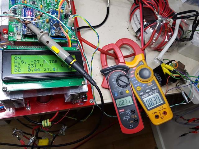 I place 6A DC across the choke and primary winding, I see 100mV This is 17mOhm DC resistance. wronger than a phone book full of wrong phone numbers |
||||
| wiseguy Guru Joined: 21/06/2018 Location: AustraliaPosts: 995 |
Ok now if you clamp one of the 240V AC capacitor leads and tell us what the capacitor current is - I am expecting around 1A. And it would be that current increased by the turns ratio that we are seeing on the primary. But I agree & have stated it is of little concern because almost all the energy put into the capacitor is returned back to the supply each cycle. There are 2 components to the story, yes there is magnetising current and there is capacitive reactance, but I am confident that the capacitive reactance is the major part of the primary current we are seeing on the unloaded inverter output. Don't get tempted to disconnect the capacitor, the inverter might get angry with you. To add clarification I am not suggesting the capacitor is a problem or that it shouldnt be there, it was a philosophical comment about the 10A Toroidal primary idling current and that the FETs are a little busy given there is no load. FYI Carefully plug the 10A capacitor on the Power-Mate Lite socket (death lead) and check the idling power at 240V probably less than 0.5W true power now look at the current on the meter screen and then tell me it doesnt load the inverter - if there is less than 0.7A I will be very surprised. The VA should show you ~ 170VA (I will indemnify your meter against damage....) If at first you dont succeed, I suggest you avoid sky diving.... Cheers Mike |
||||
| poida Guru Joined: 02/02/2017 Location: AustraliaPosts: 1388 |
I just now removed the cap, measured the power when I apply 240V AC to it. I saw 117VA. After careful discharging it from 320V to zero, the LCR meter shows 6.2uF. (The marking has "10J300VAC", no worries. Maybe it's 10 Joules at 300V. What's that mean in capacitance? Joules = 0.5 x C x V x V, so given 10 Joules, 300V, whats the capacitance? 55uF..hmm the marking is Joules not uF? ) Xc = 1/(2PI x 50 x 6.2 x 10-6) = 513 Ohms current then should be 240/513 = 0.47 A VA might now be 240 x 0.47 = 112 VA Close enough for me. So that's what I am seeing when I see phase difference between primary current and AC output voltage. It's due to the cap, not inductance. What a dill I am. Thanks for leading me to the truth, again. By the way, this 0.47A times the turns ratio (230 / 12.6) = 8.6 Which is what the 2 clamp meters see. wronger than a phone book full of wrong phone numbers |
||||
| wiseguy Guru Joined: 21/06/2018 Location: AustraliaPosts: 995 |
Poida I want to thank you for creating the inverter program & helping educate my lack of knowledge in software - if I can help impart some knowledge to help you (& others) in understanding the inverter it is my priveledge. Your contribution to this forum is outstanding. I also have gained a lot of knowledge and insight from this forum. I did that experiment with the Power-Mates ~ 2005 - so I already knew the answer. You're not a dill by any stretch - but its a good day if we learn something new or understand something better. (PS my guesstimates were based on 10uF not 6.2) I don't wish to come across as argumentative but sometimes when the point is important it is worth the discomfort. The better we all understand what is going on the better the chance for improvement & progress. That is all that interests me. Cheers ! PS Amusing to note that a capacitor is analogous to an open circuit and an inductor is a piece of low resistance wire, so the inductor must be the culprit passing lots of current. Ac does weird things to our understandings, it can turn inductors into open circuits and capacitors into short circuits - well almost. If at first you dont succeed, I suggest you avoid sky diving.... Cheers Mike |
||||
| wiseguy Guru Joined: 21/06/2018 Location: AustraliaPosts: 995 |
Poida can I ask for a little more detail about the inverter software with regard to the peak of the sinewave. What is the maximum duty cycle of the PWM output? Can it ever become 100% ie upper FET fully on during a whole 25kHz period (or more) and by deduction Bottom FET fully off for a 25kHz period (or more)? This question relates to the nano adjusting its gain higher if it senses AC out low and attempts to correct it. If it is limited to say 98% or some arbitrary value, what was the max duty cycle limit chosen? If you could provide actual minimum off time and max on time it would be most helpful - I know this is also related to processing & the nano clock f. Is the rest of the calculated values also proportional to the max duty cycle (if limited) at the peak ? I am assuming they would need to be as the sinewave would otherwise become distorted if only the maximum on time is controlled at the peak but for the rest of the sinewave it could still adjust duty cycle. If this is a dumb question I apologise in advance. This has implications for charge pump bias generation on the high side drives amongst other things. If at first you dont succeed, I suggest you avoid sky diving.... Cheers Mike |
||||
| poida Guru Joined: 02/02/2017 Location: AustraliaPosts: 1388 |
Mike, the duty cycle is a nominal 800 clocks, at 16Mhz. This means a 20kHz PWM cycle. I can, on a 20kHz cycle by cycle basis, alter the duty % as needed. From memory if you use a duty cycle of 1, you get a one clock pulse high with a 799 clock low. If you choose a duty cycle of 799 you get 100% on with zero clock periods off. This is a particular behavior of the ATMega328. In the code block "loop()" it runs once each 1/2 cycle of the 50Hz. i.e. 100Hz at zero crossing time, I determine the correction needed to obtain the required AC output voltage. This voltage is directly proportional to duty cycle %. I determine the required "power" value, and then ensure it does not fall below 0.01 or above 0.99, then multiply it by 800 and that is now the duty cycle in clocks. So, a power factor of 0.01 is equivalent to 0.01 x 800 = 8 clocks. This 8 clocks is the minimum duty cycle ever output to the gate drive ICs. And 0.99 x 800 = 792 which is the maximum duty cycle, in clocks, ever output. So the gate drive ICs will see a square wave, 20kHz, with duty cycle ranging from 8/800 to 792/800 clocks, at 16MHz. That is, 0.5uS ON, 19.5 uS OFF for the floating point power command of 0.01 and 19.5uS ON and 0.5uS OFF for a command of 0.99 I ensure there is some significant amount of ON/OFF, at the 20kHz base frequency to keep the charge pump circuit functioning. With dead time and slow rise and fall times of the total gate drive circuit, this 0.5ms pulse does not amount to much ON time for a MOSFET. Since we all here understand how DC is converted to an AC output, we size the primary windings appropriately to ensure we never need 0.99 power level. I sized my 24V primary to be 12.6V AC (which is of course 17.8 V AC p/p) yielding ample headroom for droop due to resistance. My duty cycle % would be approx. 17.8/27.4 (27.4V is my usual test voltage on the bench) so it's about 0.65, or 520 clocks at the peak of the waveform. How I modulate power output: Already we see I need a power output of 0.65 for 230V AC My soft start operates from a start point of zero power output (of course, brought up to 0.01, to ensure charge pump operation), and each 1/100 second, the following occurs: if AC output is less than set point, add 1/300 to power, convert to duty cycle clocks and move on... If AC output is greater than set point, subtract 1/300 from power, convert to duty cycle.. When soft start period has run, switch to PID closed loop, which derives a new power setting from the previous AC output and set point. This new power setting is again converted to clocks of the 800 clock base PWM cycle, and injected into the PWM timer. The above is talking about obtaining ONE number. This number represents the duty cycle at the peak of a sine wave. Scaling a sine wave is done as a linear operation. So I use the above number (power x 800, where power can range from 0.01 to 0.99) to scale the sine wave at all of the points I use along the wave. I use 200 points for the positive part of the sinewave, and 200 points for the negative part. The nano code produces an approximation of sine wave output by outputting a 20kHz square wave of varying duty cycle, with 200 separate points in the half cycle where I can define the appropriate duty cycle %. The ATMega328 has easily enough processing power to calculate quickly the needed amount of duty cycle %, when given how large the maximum point of the wave must be (the power calculation parts, in loop()..) So, every 20 kHz, the nano code is given - for this half wave only - a scale factor for each of the 200 pwm cycles of this half wave. The nano scales the sine wave's duty% value to the required power output and puts it into the timer registers. At startup, I create a table of sine wave values, scaled to 16 bit integer. This saves a huge amount of time in the 20kHz interrupt code block. The table contains 16 bit integers ranging from near zero to 64K, corresponding to the sine function of a 1/2 wave, ranging from 0.000... to 1.0 and back to 0.000 I obtain the duty cycle % value from the appropriate entry in the sine table, multiply it by the integer scale factor and then divide it by 64K (16 bits..) Very fast and it retains plenty of resolution. I can modulate the output AC by one part in 800. This means at 230V with my 12.6V primary and 27.4V DC supply, the output voltage can only range in 0.44V increments. In practice I find voltage control good enough to prevent lights flickering etc. To get finer control over AC output, make the primary winding a higher voltage. ..within loop() I obtain some value for pwr, a floating point variable. if (pwr > 0.99) pwr = 0.99; // clamp. Do math in floating point to prevent any integer overflow if (pwr < 0.01) pwr = 0.01; // it's slower. We could do clamp after conversion to int but it's your mosfets... vpwr = (int)((float)PPWM * pwr);// finally apply required PWM duty power factor to vpwr here I determine, at the present point in time of the 200 points of a 1/2 wave the required duty % lpcount is used to define the point in time of the 0-199 values of the lookup table of the 1/2 wave. The code generated from below does not do any shifts, it just copies the top 16 bits of the 32 bit result to the low 16 bits. 2 clocks for a 16 bit divide. c = (l[pcount] * vpwr) >> 16; // scale sine wave by vpwr, 32 bit integer calcs. 16 bit shift fastest of all depending if it's one or the other 1/2 wave to be driven we apply this duty cycle, in processor clocks, where the PWM clock frequency is 800 clocks OCR1B is the duty cycle register for pin 10 OCR1A is the same for pin 9 (or arse about, I can't be bothered to look at the cpu manual) v1low is the flag to determine if we are driving one or the other of the 1/2 wave parts. if (v1low == 1) // alternate between 2 output compare pins. Get a full 50Hz waveform OCR1B = c; // 1/2 out this pin else OCR1A = c; // and then 1/2 out this pin. Other code in "ISR(TIMER1_OVF_vect)" is mainly related to the mains sync with the needed bit to switch from one to the other 1/2 cycle which is to toggle "v1low" from 1 to 0 and back. wronger than a phone book full of wrong phone numbers |
||||
| wiseguy Guru Joined: 21/06/2018 Location: AustraliaPosts: 995 |
Thank you form a well written descriptive and very detailed reply. Conceptually I understand (I think...) what is going on - could I recreate the explanation - no to vaguely. I did know about the 20kHz but I keep referring to it as 25 - sorry. It will take many more reads of your words and a lot more hands on with the nano & code to fully understand. The essential answers I wanted are that I understand that the duty cycle remains below 100% and above 0% for any condition which is what I expected and as it should be. This is related to the next part. I am also wondering about the toroidal turns ratio choice and how to best select it. Something doesnt feel quite right about running something at a gain of say 50 or 60% for the desired 240V output. If I play devils advocate for a moment and imagine a glitch causing a gain jump to maximum, in theory the output voltage could nearly double - if the toroid doesnt saturate first and the FETs dont mind at the minimum 4X and worst case massive? increase of power. Ideally if the nano code is unchanged from present and the battery voltage is near minimum, lets assume gain is at 90% or 95% of maximum and the inverter is fully loaded then whatever turns ratio would then provide the 230V or 240V mains you are after sounds like a more ideal approach? I know this is an inside out way of transformer design but it is the overall concept I want to try to get across. For those who wish to back feed from an AC coupled topology this approach is probably not at optimum for ensuring best charging levels ? If you have a fixed transformer and dont want to change windings (turns ratio) there are other options; add or take a cell out if you have individual cells, be flexible & happy to have somewhere between 230 & 240V for the output. But to make the code safer the regime could also be changed as below. Limit the maximum gain as follows, apply the minimum battery input voltage, scale a nano to drive the inverter to 230/240V @ full load then add another 5 or 10% margin and store it as the maximum gain. Reducing the gain in normal operation for higher input voltages is a given, but this would limit the output to a safer maximum level if it ever went feral for any reason. Peter I am not asking for any changes to or criticising your current code I am playing devils advocate and what if scenarios. I look forward to any constructive feedback. PS this isnt over yet - there is still a choke discussion coming..... If at first you dont succeed, I suggest you avoid sky diving.... Cheers Mike |
||||
| poida Guru Joined: 02/02/2017 Location: AustraliaPosts: 1388 |
My nanoverter code behaves the same as the EG8010 in the area of maximum output voltage. I think we all have no problem with this and so size the primary winding voltage accordingly, to balance primary winding current, copper wire area/cost, physical building effort, battery low voltage cut off limit etc. I could easily add a "#define" at the top of nano1 code, to define the maximum PWM duty% ever output. The nanoverter board design does not permit this feature to be controlled by nano2 and it's nonvolatile ram. Since the code is open source, it's simple for the users to change the single line if (pwr > 0.99) pwr = 0.99; // clamp. to something smaller than 0.99. I want 0.99 to be the maximum PWM duty% ever sent to the gate drive ICs. Any more and we risk not having enough duty cycle to run the charge pump. For your enjoyment and further exploration, I made a version of the nano1 code that now operates as a variac. It might be of no use whatsoever but I know I used such code when first exploring PWM, MOSFET bridges, gate drive and all that. It permits us to see what happens when 0.99 power is applied to the basic PWM code. Handy to see what AC voltage a toriod starts saturating at, for one use. There could be many. To use it, load the below code into a nano, and to run it, pull pin8 high. To stop, pull pin 8 low. Put the output of a potentiometer into analog input 4, varying from 0 to 5 volts. The usual gate drive IC outputs for the IR21844 and other chips are on pins 9,10 and pin 5 is the shutdown. This code does not require a nanoverter board. You just need a nano and 2 1/2 bridge gate drive ICs, 12V supply for the ICs and the charge pump diode/caps. You can build the lot on a breadboard and it will run fine. Here is a video of it in action, using the nanoverter board and the test Madness power board. I loaded the code into nano1. video I could run this particular toroid up into 270V AC without complaint. I think we all should have one of these, since a transformer type variac costs a lot, even the low power types. I commented the code in the hope you will find it worthwhile reading. 2019-06-09_140729_nano_variac.ino.zip wronger than a phone book full of wrong phone numbers |
||||
| wiseguy Guru Joined: 21/06/2018 Location: AustraliaPosts: 995 |
Sorry for the belated reply I have been busy since yesterday, bashing the metalwork into shape which had to be done before I start to populate the PCB. Here is what Ive been up to - and I ran out of FETs until my slow boat from China arrives  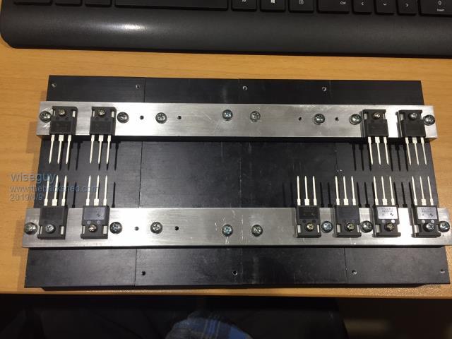 The FETs are mounted on a 25mm x 10mm Aluminium bar, the FET legs will be bent up to go into the PCB, the screws holding the FETs are temporary and will finally go through the PCB and sandwich the FET between the PCB & heatsink. 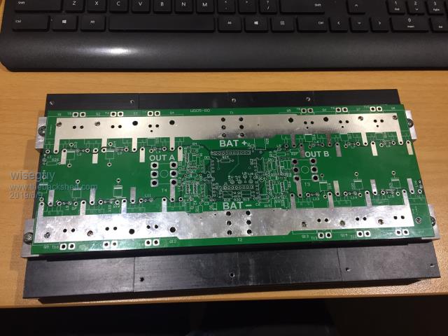 The 4 heat sinks were left over from an old project seemed like a good way to use some up... I have not had a chance to open the variac nano code yet - it will come in very handy for testing purposes & I appreciate you taking the time to comment it for me - should be a great help in following and understanding. The max duty cycle adjustment is fine as a user modified setting. If it is used correctly then if the VFB feedback failed maybe the output would climb to 250 or 260 volts which is much better than maybe 300 or 400V. I highlighted this issue mainly for the less technical who may not realise what could happen if VFB failed and they were using a 50 or 60% of full scale gain on a lower voltage primary. Will have a look at the Variac code tomorrow - I dont have Arduino environment on this laptop. If at first you dont succeed, I suggest you avoid sky diving.... Cheers Mike |
||||
| wiseguy Guru Joined: 21/06/2018 Location: AustraliaPosts: 995 |
Finally today I hooked up a large toroid and a 30V 5A supply to begin testing my inverter. Everything is working essentially as expected and it even ran a Makita hand drill (only ~ 140V out), but it all works a treat. However looking at the pulse trains for the sine-wave generation I noted the following behaviour of the Toroidal drive First pulse � � �~ 1.65uS � �+ 48uS delay Second pulse � �missing � � (50uS delay) � � Third Pulse � � �~ 940nS � � + 49uS delay Fourth pulse � �~ 1.65uS � �+ 48uS delay Fifth pulse � � � ~ 2.44uS � �+ 47uS delay Sixth pulse � � �~ 3.24uS � �+ 47uS delay Next I checked the same pulses strait from the nano and got the following results First pulse � � � �~ 1.6uS � � + 48uS delay Second pulse � �~ 70nS � � �+ 50uS delay Third Pulse � � � �~ 910nS � �+ 49uS delay Fourth pulse � � ~ 1.6uS � � + 48uS delay Fifth pulse � � � �~ 2.4uS � � + 48uS delay Sixth pulse � � �~ 3.2uS � � �+ 47uS delay The last 3 pulses from the other end of the half sine waveform were Third to last pulse � � ~ 3.2uS �+ 47uS delay Second to last pulse �~ 2.4uS �+ 48uS delay Last Pulse � � � � � � � �~ 1.6uS �+ 49uS delay The other half sine-wave phase gave the same results. �The second pulse (70nS)is too small to get through the FOD3182 opto-coupler that is why it disappeared from the FET power drive to the toroid. Poida, I suspect that the two half sine-waves have essentially the same shape and probably deliver equal energy content albeit with some slight distortion. There does appear to be something strange occurring though especially with the first and second pulse being 1.6uS and then 70nS respectively, they should be getting bigger not smaller. Also I would have expected the first few and last few pulses to be the same. � I am only bringing this to your attention as I suspect there is something going on that you may not be aware of. �Why can we resolve in ~ 800nS steps starting from zero on the up (ok starting from 1.65uS then zero) but on the way back, the final 2 pulses are 2.4uS and 1.6uS - I would expect the first two pulses on the up to be 1.6 then 2.4 ? Note: This is an open loop result where the AC feedback is currently too small to regulate, so the gain of the nano has gone to maximum. �I have found in the past that when something is happening that is not fully understood other things may be occurring or affected that may have the potential to behave in a negative manner (bite you in the ass later....). Having symmetrical drive either side of the 90 degree peak gives lowest distortion & having symmetrical positive going and negative going half sine-waves are highly desired (essential?) to eliminate flux walking. In an ideal world I believe the best results might come from a look up table of a single 90 degree sine portion that drives a sine wave to 90 degrees and then reverts from max back to zero using the same steps in reverse and the next 180 degrees for the other drive is derived exactly the same as the first 180 degrees. The gain would be constant and uniform for each whole 360 degree cycle. Read the feedback dc level and then use it to create the next (gain compensated) 90 degree look up table for the next 360 degrees. �This would ensure each complete cycle, once started would finish with exactly equal energy content and symmetry for both half sine-waves. I am not suggesting the look up table contents actually has a fault or bad values but that something is causing some unexpected results to occur. I do have the beginnings of an inverter showing promising signs of potentially working - albeit - so far not at full output yet - a quick clip showing a messy bench and a Makita hand drill being driven Here . �Idling power at 30V in is ~ 185mA (5.5W) Edited 2019-09-30 00:23 by wiseguy If at first you dont succeed, I suggest you avoid sky diving.... Cheers Mike |
||||
| Warpspeed Guru Joined: 09/08/2007 Location: AustraliaPosts: 4406 |
I have a similar situation with my warpverter, in that I calculated the values for a ninety degree quarter sinusoid, then join four of those up to get a complete 360 degree full sine wave. At the peaks and zero crossings there is sometimes a slight discontinuity because of cumulative mathematical rounding errors that creep in. If you look at it on an oscilloscope it appears as a small kink in the waveform. However, if the whole waveform is fed into a distortion analyser, the total harmonic distortion figure looks very good. Everything runs fine off the grid, and I have measured over five percent distortion. A tiny imperfection in your inverter that probably has less than one percent total harmonic distortion is definitely nothing to worry about. Cheers, �Tony. |
||||
renewableMark Guru Joined: 09/12/2017 Location: AustraliaPosts: 1678 |
I have no idea if what you found is significant, but for the record, mine has run the house non stop for over 6 months now, and no problems yet. That's a pretty good soak test. Cheers Caveman Mark Off grid eastern Melb |
||||
| poida Guru Joined: 02/02/2017 Location: AustraliaPosts: 1388 |
Mike, I did a quick hack of the nano1 code to obtain how long V1 and V2 are switched on for. Let V1 and V2 be the inverter outputs for the 2 half bridges. When V1 is on for longer than V2, we will see a DC current appear on V1 compared to V2. I will see a unbalance in the duty cycle count totals if this is the case. The hacked code sums the PWM duty (in cycles) for both V1 and V2. I only start summing V! and V2 total cycle counts when the ramp up is complete. In my test, there is no inverter present, no Vfb so the ramp up continues to 100% power and stays there. I printed the difference in duty cycles for V1 and V2 at the time when v1low = 1 and uf = 1, that is some fixed time in the 50Hz output. I see a constant value of (V1-V2) which in this test is 12 cycles. The 12 cycles difference is likely due to one half cycle not quite being at 100% when the soft start completes. The important thing is that this difference does not increase or decrease. It stays constant after the soft start completes. It stays at 12 cycles... this means there are exactly the same number of clock cycles switching V1 ON as there are clock cycles switching V2 ON. The V1 waveform has the same form as V2, down to the clock cycle. But this is when there is no voltage feedback. This condition is important. Vfb might end up causing one 1/2 cycle to become larger than the other at some undefined time, and then Vfb might require the 1/2 cycle to become smaller at some other, later time. The magnitude of the changes might not exactly add up to 0.0000 at any time we chose to measure. Nano1 code uses the same lookup table for duty % for both 1/2 cycles of the 50Hz output. One output pin is driven low and the other is driven by the PWM sine wave. Pins 9 and 10 are the driven outputs so we will see pin9 low and pin10 SPWM for a 1.2 cycle, then pin10 low and pin9 SPWM for the next 1/2 cycle. Here are the values in the lookup table for a power of 0.99 which is the maximum the code will ever output pins 9 and 10. index 0 -> 0 cycles ON index 1 -> 12 cycles ON index 2 -> 24 cycles ON index 3 -> 37 cycles ON index 4 -> 49 cycles ON index 5 -> 61 cycles ON index 6 -> 74 cycles ON index 7 -> 86 cycles ON index 8 -> 98 cycles ON index 9 -> 111 cycles ON index 10 -> 123 cycles ON index 11 -> 135 cycles ON index 12 -> 147 cycles ON index 13 -> 159 cycles ON index 14 -> 171 cycles ON index 15 -> 183 cycles ON index 16 -> 195 cycles ON index 17 -> 207 cycles ON index 18 -> 219 cycles ON index 19 -> 231 cycles ON index 20 -> 243 cycles ON index 21 -> 255 cycles ON index 22 -> 266 cycles ON index 23 -> 278 cycles ON index 24 -> 290 cycles ON index 25 -> 301 cycles ON index 26 -> 313 cycles ON index 27 -> 324 cycles ON index 28 -> 335 cycles ON index 29 -> 346 cycles ON index 30 -> 357 cycles ON index 31 -> 368 cycles ON index 32 -> 379 cycles ON index 33 -> 390 cycles ON index 34 -> 401 cycles ON index 35 -> 411 cycles ON index 36 -> 422 cycles ON index 37 -> 432 cycles ON index 38 -> 443 cycles ON index 39 -> 453 cycles ON index 40 -> 463 cycles ON index 41 -> 473 cycles ON index 42 -> 483 cycles ON index 43 -> 493 cycles ON index 44 -> 502 cycles ON index 45 -> 512 cycles ON index 46 -> 521 cycles ON index 47 -> 530 cycles ON index 48 -> 539 cycles ON index 49 -> 548 cycles ON index 50 -> 557 cycles ON index 51 -> 566 cycles ON index 52 -> 575 cycles ON index 53 -> 583 cycles ON index 54 -> 591 cycles ON index 55 -> 600 cycles ON index 56 -> 608 cycles ON index 57 -> 615 cycles ON index 58 -> 623 cycles ON index 59 -> 631 cycles ON index 60 -> 638 cycles ON index 61 -> 645 cycles ON index 62 -> 652 cycles ON index 63 -> 659 cycles ON index 64 -> 666 cycles ON index 65 -> 673 cycles ON index 66 -> 679 cycles ON index 67 -> 685 cycles ON index 68 -> 691 cycles ON index 69 -> 697 cycles ON index 70 -> 703 cycles ON index 71 -> 709 cycles ON index 72 -> 714 cycles ON index 73 -> 719 cycles ON index 74 -> 725 cycles ON index 75 -> 729 cycles ON index 76 -> 734 cycles ON index 77 -> 739 cycles ON index 78 -> 743 cycles ON index 79 -> 747 cycles ON index 80 -> 751 cycles ON index 81 -> 755 cycles ON index 82 -> 759 cycles ON index 83 -> 762 cycles ON index 84 -> 765 cycles ON index 85 -> 768 cycles ON index 86 -> 771 cycles ON index 87 -> 774 cycles ON index 88 -> 776 cycles ON index 89 -> 779 cycles ON index 90 -> 781 cycles ON index 91 -> 783 cycles ON index 92 -> 785 cycles ON index 93 -> 786 cycles ON index 94 -> 787 cycles ON index 95 -> 789 cycles ON index 96 -> 790 cycles ON index 97 -> 790 cycles ON index 98 -> 791 cycles ON index 99 -> 791 cycles ON index 100 -> 791 cycles ON index 101 -> 791 cycles ON index 102 -> 791 cycles ON index 103 -> 791 cycles ON index 104 -> 790 cycles ON index 105 -> 790 cycles ON index 106 -> 789 cycles ON index 107 -> 787 cycles ON index 108 -> 786 cycles ON index 109 -> 785 cycles ON index 110 -> 783 cycles ON index 111 -> 781 cycles ON index 112 -> 779 cycles ON index 113 -> 776 cycles ON index 114 -> 774 cycles ON index 115 -> 771 cycles ON index 116 -> 768 cycles ON index 117 -> 765 cycles ON index 118 -> 762 cycles ON index 119 -> 759 cycles ON index 120 -> 755 cycles ON index 121 -> 751 cycles ON index 122 -> 747 cycles ON index 123 -> 743 cycles ON index 124 -> 739 cycles ON index 125 -> 734 cycles ON index 126 -> 729 cycles ON index 127 -> 725 cycles ON index 128 -> 719 cycles ON index 129 -> 714 cycles ON index 130 -> 709 cycles ON index 131 -> 703 cycles ON index 132 -> 697 cycles ON index 133 -> 691 cycles ON index 134 -> 685 cycles ON index 135 -> 679 cycles ON index 136 -> 673 cycles ON index 137 -> 666 cycles ON index 138 -> 659 cycles ON index 139 -> 652 cycles ON index 140 -> 645 cycles ON index 141 -> 638 cycles ON index 142 -> 631 cycles ON index 143 -> 623 cycles ON index 144 -> 615 cycles ON index 145 -> 608 cycles ON index 146 -> 600 cycles ON index 147 -> 591 cycles ON index 148 -> 583 cycles ON index 149 -> 575 cycles ON index 150 -> 566 cycles ON index 151 -> 557 cycles ON index 152 -> 548 cycles ON index 153 -> 539 cycles ON index 154 -> 530 cycles ON index 155 -> 521 cycles ON index 156 -> 512 cycles ON index 157 -> 502 cycles ON index 158 -> 493 cycles ON index 159 -> 483 cycles ON index 160 -> 473 cycles ON index 161 -> 463 cycles ON index 162 -> 453 cycles ON index 163 -> 443 cycles ON index 164 -> 432 cycles ON index 165 -> 422 cycles ON index 166 -> 411 cycles ON index 167 -> 401 cycles ON index 168 -> 390 cycles ON index 169 -> 379 cycles ON index 170 -> 368 cycles ON index 171 -> 357 cycles ON index 172 -> 346 cycles ON index 173 -> 335 cycles ON index 174 -> 324 cycles ON index 175 -> 313 cycles ON index 176 -> 301 cycles ON index 177 -> 290 cycles ON index 178 -> 278 cycles ON index 179 -> 266 cycles ON index 180 -> 255 cycles ON index 181 -> 243 cycles ON index 182 -> 231 cycles ON index 183 -> 219 cycles ON index 184 -> 207 cycles ON index 185 -> 195 cycles ON index 186 -> 183 cycles ON index 187 -> 171 cycles ON index 188 -> 159 cycles ON index 189 -> 147 cycles ON index 190 -> 135 cycles ON index 191 -> 123 cycles ON index 192 -> 111 cycles ON index 193 -> 98 cycles ON index 194 -> 86 cycles ON index 195 -> 74 cycles ON index 196 -> 61 cycles ON index 197 -> 49 cycles ON index 198 -> 37 cycles ON index 199 -> 24 cycles ON index 200 -> 12 cycles ON Nano1 code runs through the index of 0 to 200 INCLUSIVE. It runs through this table each 1/2 cycle. 200 entries, 800 cycles per pwm and 16MHz clock means a 20KHz PWM with a minimum PWM width of zero and a maximum of 800 clocks. I like to not let it go to 800 clocks, since that would mean the PWM would be permanently ON and no pulsing, and importantly, no pulsing for the charge pump. So I limit it to 0.99 of 800 clocks, leaving a short OFF period during the full power PWM pulse, to keep the charge pump alive. The value for index 0 = 0 cycles and we never get to index = 201 So it is not exactly symmetrical, but near enough. (where symmetrical means the same number of cycles ON during the ramp UP as there are during the ramp DOWN in a half cycle.) I could modify things so it is symmetrical about the maximum of the sine wave. I do not think this is a problem. 12 cycles = 12/16Mhz = 0.75uS pulse width. The IR2184 has a nominal dead time of 500ns. In the case of a 12 cycle pulse, I suspect not a lot of ON time will be seen on the half bridge after dead times and switch delays take their tolls. I wonder if I have addressed your concerns, but in any case at least this will help us understand the nano1 SPWM output. wronger than a phone book full of wrong phone numbers |
||||
| poida Guru Joined: 02/02/2017 Location: AustraliaPosts: 1388 |
The first and second pulse widths are right about when the control loop does it's modification to the required power output. It's possible that early in the half wave the Vfb control loop chooses a smaller power output that then will scale the PWM duty width to "small". But I don't think so. I would like to think that under a relatively steady state condition, well past soft start, the changes to the power output would be small. I have spent a fair bit of time in the past looking at PWM output during the AC output zero crossing. I concluded that I could obtain perfect PWM timing if I used FPGA. I don't want to go down that rabbit hole. The ATMega328P offers near perfect timing and it's programmable and we can control it with OUR programs. (not like the EG8010 which is fixed in function and has some drawbacks) I see with the current nano1 code the PWM is not optimal. pin10 = OC1B pin9 = OC1A v1low = 1 when pin10 is SPWM and pin9 is pulled HIGH Yellow = v1low (v ONE low) Light Blue is inverted pin10 low side gate drive Pink is inverted pin9 low side gate drive Here is the zero crossing where v1low drops from 1 to 0 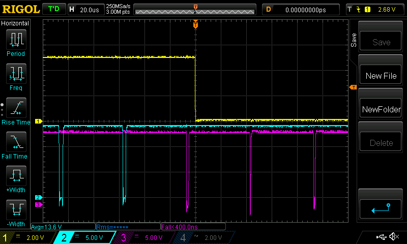 and here is when it rises from 0 to 1 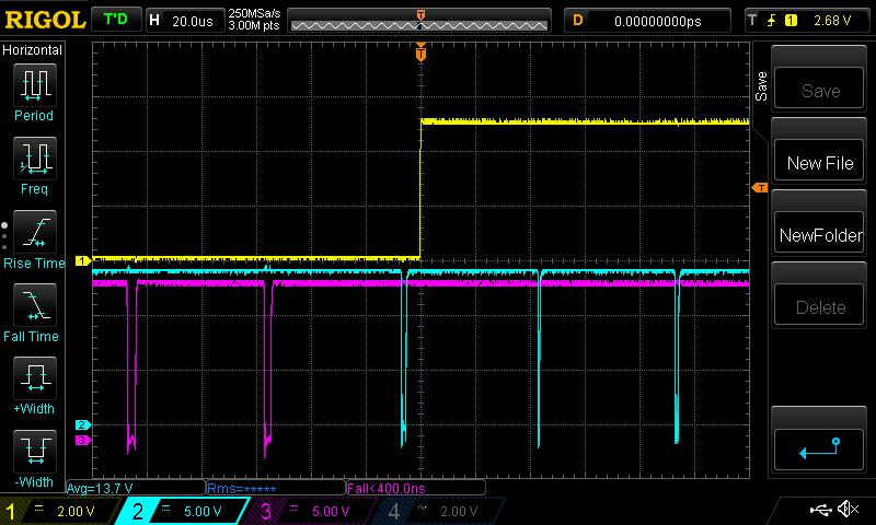 We can see in both cases there is a PWM pulse that should not be there The pulse about 5 uS before the yellow trace changes state. Maybe no so much "should not be there" as it's the wrong pulse out the right pin. Also there could be an "out by one" error with the pwm table counting. Maybe I never get to the entry numbered 200.. and then it's time to switch over to the other 1/2 bridge. I could fix this, maybe. I doubt it though. I also doubt it will result in any significant issues either if I leave it be. here is the code that prints the difference in clock cycles if you want to see it. nano_1_v8_pwm_sum_test_wg.ino.zip load this into a spare nano or uno and see the output in the serial console You will need to pull pin8 to 5V to make the inverter code run. press reset button and watch variable sst grow(slow start..) to 251 when the totals of V1 and V2 clock cycles comparison starts. It will show some value and I don't care what it is but the important thing is that it does not change. wronger than a phone book full of wrong phone numbers |
||||
| wiseguy Guru Joined: 21/06/2018 Location: AustraliaPosts: 995 |
Peter, thanks again for a very detailed explanation. I do not believe we are anywhere remotely close to requiring a FPGA to generate our wave-forms. The pulse you said should not be there for either waveform is what started me off in my post. It is essentially I think the same width as the (second/third ? ) step in the table depending on whether you start from zero. How is this 1 pulse being output just before the zero crossing (I assume the change of state of the yellow is zero?) I believe the first two pulses should probably not be there. The first pulse is ~1.6uS wide the next pulse is 70nS wide. The third pulse is ~900nS wide. At the other end of the table, coming back to zero the final pulse is 1.6uS. To my software challenged eyes I will describe what it looks like to me. The waveform is reading the whole table, but shifted to the left by one location. If it was shifted to the right the last pulse should (could) be around 900uS, the first pulse on the table would then be ~ 70nS (close enough to zero) and all would agree with your table ? �The first genuine pulse after zero would be ~ 900nS, the last would also be 900nS and all would be well ? I have seen >= or <= or > or < usage cause tables to be read shifted by one by choosing the wrong one in lieu of another. I am not trying to find fault with your software or nit picking but it never sits well with me when I see different behaviour to what I expect. �My highlighting the anomaly is purely in the cause to achieving the best results going forward. I think it unwise to output a 70nS pulse - it is unlikely to get through most drive circuits and if it did make it through it is an undesirable width in my opinion. �Perhaps any location in the table that will output a pulse less than 500nS should be set to zero ? If this is already being done where does the 70nS pulse come from? The last query is that I interpreted that you said the minimum pulse width output generated is 750nS. But it appears that if I ignore the 70nS pulse, the narrowest one I see is ~ 900nS and the increments from that appear ~ 800nS (maybe 750) it is not causing me to lose sleep but should this 900nS be closer to ~ 750nS ? Below I tried to relate what I saw at the beginning and end of the pulse train to your table - maybe this is not the right way of looking at it ? � � � � � � � � � � � � � � � � � � � � �� � � �� � ��Measured result index ? �-> 24 cycles ON ? ........1.6uS ? �This is the first pulse output in the train index 0 �-> 0 �cycles ON.............70nS (1cycle on?)(very close to zero) index 1 �-> 12 cycles ON........... 900nS index 2 �-> 24 cycles ON........... 1.6uS index 3 �-> 37 cycles ON........... 2.4uS index 4 �-> 49 cycles ON........... 3.2uS ....... index 198 �-> 37 cycles ON......... 3.2uS �above we get 2.4uS for 37 cycles index 199 �-> 24 cycles ON......... 2.4uS �above we get 1.6uS for 24 cycles index 200 �-> 12 cycles ON......... 1.6uS �above we get 900nS for 12 cycles 1.6uS is the last pulse I see in the train - there is no 900nS (750nS) pulse before zero ? To try to clarify, the last pulse I see (index200?)is 1.6uS. Was this read from location 200 (I expected that from 199), or was the wrong information in index 200 ? If there are 12 cycles at index1 and index200 the first and last pulses should both be ~900nS ? Did we truncate at 200 and then it was never output ? (I havent confirmed that there are actually 200 outputs in a string.......) Sorry to labour this I only just noticed you were suggesting similar in your last reply - I missed it. A colleague I used to work with would sometimes exclaim that some issue was of monumental inconsequence - maybe this all falls into that category...... Edited 2019-10-01 19:38 by wiseguy If at first you dont succeed, I suggest you avoid sky diving.... Cheers Mike |
||||
| poida Guru Joined: 02/02/2017 Location: AustraliaPosts: 1388 |
Mike, I've played with the code a little, it removes the initial too wide pulse at the start of each 1/2 wave. I'm at work and only have the 2 channel DSO, so we can not see the v1low trace but imagine the transition from low->high is at the centre of the screen. 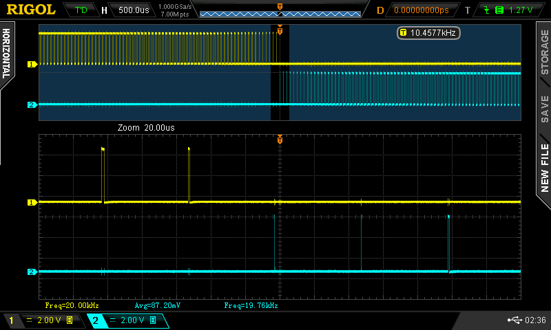 Is this what you are looking for? It's likely some sort of "out by one" type of error, but with minor consequences that alter the shape of the output waveform a little. this is the code that produces the above: nano_1_v7_no_bessel_mike.zip that final pulse of the Yellow trace is about 1.0uS wide. Dead time function will place approx 0.5uS dead time on both sides of (this pulse width - 2x dead time) which will be about zero effective pulse width. This is when using the IR2184 which inserts a constant 0.4-0.5 uS DT Edited 2019-10-02 08:53 by poida wronger than a phone book full of wrong phone numbers |
||||
| wiseguy Guru Joined: 21/06/2018 Location: AustraliaPosts: 995 |
Thanks for your on-going efforts Peter - I will try later today. "it removes the initial too wide pulse at the start of each 1/2 wave" Is this really the beginning of a half wave? Should this really read - it removes the initial too wide pulse at the end of the previous 1/2 wave that appeared on the wrong output pin (that should have remained at zero) - just before the zero cross ? This is an innocent question but I am playing devils advocate to highlight the inner meaning - I might not be getting something. It appears the pulse is now skinnier but again - I am software challenged & make no bones about it - I would have expected the ports for pins 9 & 10 are only enabled after the corresponding zero cross has occurred. I am looking at the traces above - not ideal - the narrow pulse seems to now occur twice, once just before zero cross, once after at the beginning of the pulse train. This will probably have no detrimental affect overall - but for my interest how does a 70nS pulse occur when it should have been either zero or 12 pulses wide? BTW my hardware can drive the FETs from ~ 150-200nS pulses from the uC. Edited 2019-10-02 09:20 by wiseguy If at first you dont succeed, I suggest you avoid sky diving.... Cheers Mike |
||||
| poida Guru Joined: 02/02/2017 Location: AustraliaPosts: 1388 |
I know it's not ideal. I probably spent over a week, at work, (when paid by my boss to do other things) looking at this particular problem. I tried different microcontrollers (the ATMega328p as found in the Nano and Uno as well as the Arduino Due, using a SAM3 uC) Detail changes in code have resulted in what we have here: nano1 v7 is the best. It's better than EG8010 in the output shape and the code does not emit spurious gate output signals upon startup as the EG8010 does. The imperfect PWM timing problems lie in the areas that encompass 1 - the timing of execution of code within the 20kHz interrupt block with respect to when exactly the effects of updating the PWM duty register will be seen in the output of the subsequent PWM pulse. 2 - changing the mode of operation from PWM to plain old digital output, the timing of this is critical. 3 - small high power pulses of current, and which rise and fall very quickly, will upset the quality of the AC output waveform so I had to minimise the errors of timing as best I could. The 16Mhz 328p microcontroller gave me the best combination of timing of the two outputs. I found "errors" or non-optimal results always smaller than about 1uS The SAM3 chip on the Due, even though it runs at 84Mhz, could not produce the tightly co-ordinated changes of outputs I could easily get with the Nano/328p Errors from the Due were of the order of 20uS and so were likely to inject significant distortions. I had a play with a modified nano1 code that let me adjust the over-run of the PWM sin wave via a potentiometer. I could make the 1/2 wave terminate a few PWM cycles early, or let it run right up to the end (that is to the 200th PWM cycle) and still have significant pulse width. I saw not a lot of change, but I kept the control range to only +/- a few PWM cycles. What we have here is good enough for most purposes. Even government work. wronger than a phone book full of wrong phone numbers |
||||
