
|
|
Forum Index : Electronics : Poidas "Inverter Software Control" Topic.
| Author | Message | ||||
| wiseguy Guru Joined: 21/06/2018 Location: AustraliaPosts: 1206 |
Thanks Poida all becoming clearer - if I can summarize in my own words with some emphasis on what I may have wrong. Vfb is sampled and stored ~ 4K times each 360 degrees? The stored value that will be used for correction will be the one immediately prior to the zero cross? the other 3999 values are just redundant now? The correction is applied to (creates) a whole table of values that form either a whole 360 cycle or 180 half cycle depending on the version of code being used? For some reason I thought there was some point at ~ 2mS after the zero cross where Vfb played a part - but I may be barking up the wrong tree. There is distortion (~ 3 cycles) on the first 90 degrees and the 180 - 270 degrees of my first cro shot above that are essentially where the sample and hold becomes live again. From inspection it appears like the table has output values that cause this. Is it possible that the varying Vfb did this somehow ? Edited 2019-11-12 10:30 by wiseguy If at first you dont succeed, I suggest you avoid sky diving.... Cheers Mike |
||||
| poida Guru Joined: 02/02/2017 Location: AustraliaPosts: 1432 |
"Vfb is sampled and stored ~ 4K times each 360 degrees?" no, 4KHz, so that's 4K/50 or 80 times each 360 degrees. "The stored value that will be used for correction will be the one immediately prior to the zero cross? the other 3999 values are just redundant now?" yes, only one is used when there is no digital filtering. All wasted samples except each one near zero cross. It's not a problem, just a left over from previous versions when I needed these samples. There were times when I wanted to see the filtered Vfb signal for the entire 360 degrees. This showed how the LP filter performed. "For some reason I thought there was some point at ~ 2mS after the zero cross where Vfb played a part - but I may be barking up the wrong tree." certainly barking. The only sample that effects the power level output is the sample of Vfb obtained prior to when the variable "uf" is set =1 which causes the control loop code to execute once for that 1/2 wave. "There is distortion (~ 3 cycles) on the first 90 degrees and the 180 - 270 degrees of my first cro shot above that are essentially where the sample and hold becomes live again. From inspection it appears like the table has output values that cause this. Is it possible that the varying Vfb did this somehow ?" No. I am clear in this view. The changes made to the amplitude of the sine wave PWM are made quite close to zero crossing, and this change is to alter the power level from the current value (effecting the just completed 1/2 wave) to the new value, which will then control the power level for the next 1/2 wave. The new value remains constant for the entire 1/2 of the wave. A constant scale factor for the 200 PWM pulse widths that make up the 1/2 sine wave. Most times the change of the scale factor from 1/2 wave to 1/2 wave are small. This results in zero changes to the few PWM pulses either side of the zero crossing. The wobbles we see are due to the non-continuous drive of current into the primary winding resulting from the wider (in time) spaced narrow width pulses from the bridge. These pulses excite a wide range of frequencies with large amounts of power and we tame them to the best of our ability with the LC LP filter on the primary/secondary windings. You probably will find you can quench these wobbles with a larger filter cap alone. Since the wobbles were reduced with a change in filter cap, I find no reason to think "the wobbles are due to non-optimal PWM output" Notice that putting a large load on the inverter reduces the wobbles. The PWM pulse train remained the same in all ways except the widths of all the pulses would have been wider by some small factor. (larger load -> wider PWM pulse widths) Edited 2019-11-13 18:14 by poida wronger than a phone book full of wrong phone numbers |
||||
| wiseguy Guru Joined: 21/06/2018 Location: AustraliaPosts: 1206 |
Thanks again for your detailed reply, it has all helped greatly in my understanding of the software. If it has come across that I am complaining about or criticising in any way your excellent work, that would be an incorrect interpretation. To understand or have a hope of making any improvement to something that exists first requires a fairly detailed understanding of it. I think the 2mS red herring was the amount of time my sample and hold remained stable after the zero cross - it was the safety margin - its only relationship to Vfb. Whilst I understand the ripple comments you made re varying pwm widths etc I still have a slight problem with one detail that caused me to question what was happening. The variac code showed no sign of this distortion loaded, unloaded varied over 180 - 250V at various loads etc and appears to be totally unconditionally stable except for voltage droop at higher loads - I have not been able to replicate any wiggles on the sinewave running this code. I am currently building up a totally analogue external integrator/summer of a pot setting and the Vfb signal to regulate the output voltage using the variac code, maybe I can faithfully re create those wiggles using an analogue control loop Ā  - (I do actually expect to have issues - its just what happens sometimes with servo loops & high power) Ā - (I do actually expect to have issues - its just what happens sometimes with servo loops & high power) Ā I also apologise for having re asked some/many questions and been a bit of a pest in my attempts to re-understand things, but in my defence we have had a serious house build going on in the background over 9 months that has driven us to distraction with multiple issues but is now just a few weeks away from being finished. I will never ever build again !! Edited 2019-11-13 19:30 by wiseguy If at first you dont succeed, I suggest you avoid sky diving.... Cheers Mike |
||||
| poida Guru Joined: 02/02/2017 Location: AustraliaPosts: 1432 |
Wiseguy, there will never be any need for you to apologise to me. I am always ready to read your posts and answer questions/hack code/test things as required. The variac code was just a quick hack to give me a tool to enable gradual application of AC power when testing the volts/turn of a huge toroid. It surely had other uses too. I am too tight with money to buy a variac so I thought, "I wonder.." I am in the middle of building 2 nanoverter driven Madness totem pole board systems. One for me and one for me mate. I like the single toriod PWM based inverter designs. wronger than a phone book full of wrong phone numbers |
||||
| wiseguy Guru Joined: 21/06/2018 Location: AustraliaPosts: 1206 |
I also like the simplicity of HF single toroid inverter designs. Ok there might be some black magic going on & required to make it work but when the recipe works well & its not difficult to follow, it should be easy to replicate for others with the advantage of the simpler transformer approach. Ben and Amber have had great fun with their little china board and can't easily kill it, despite trying hard. The ribbon cables connecting the nano controller to the power section are not at all touchy. I believe they could be 2 metres long and it should not matter a bit. That is not to say I dont like the Warpverter if you are happy to wind 4 Toroids and a fair bit of engineering to connect and house it all they are simple, reliable and capable of real grunt, for bullet proof power in the multi kW region they are the way to go. I have been running many A/B tests today between the nano inverter code and the variac code, looking critically at the results. I must agree I can see wiggles on the variac code as well, just a bit less pronounced. I recently acquired (bought) some decent Tektronix current probes, the A6302, 20A/50APk to 50MHz B/W, and an A6303 100A/500APk to 15MHz B/W. I will post some interesting shots in due course of what causes the wiggles - I'm getting to see stuff previously invisible but very revealing & interesting. Yes there are weird harmonic artefacts present that I want to investigate further and see how they change with transformer tuning etc. Yes Tony I admit it, I grabbed any old capacitor I think it was 2u2 and let it rip lol. Putting a 10u made no difference to Idle current even though there was then nearly 1A of secondary current circulating. I will try tuning it to 50Hz and 75Hz just to see what happens to the primary currents (CRO) if the inverter gets angry with me so be it. The Variac circuit (without the analogue feedback regulation) is just like this Nano Variac.pdf This drives the LED inverse parallel optos on my power board just fine. If at first you dont succeed, I suggest you avoid sky diving.... Cheers Mike |
||||
| Warpspeed Guru Joined: 09/08/2007 Location: AustraliaPosts: 4406 |
The voltage droop at higher loads should be acceptable in a practical inverter. Its going to be totally unconditionally stable, because there is nothing fed back from the output to make it unstable. It simply cannot surge or oscillate or chase its tail. Why not take Poida's varic code, invert the output from the a/d and feed the voltage control potentiometer straight off the raw incoming dc. When properly scaled, if the dc input voltage falls, the varic cranks up the ac output voltage by the exact same proportion. Its going to be very fast acting and will be unconditionally stable. Its obviously going to have some voltage droop at high loading of course, but all things considered, its arguably a very worthwhile overall compromise. And its dead simple. Cheers, ĀTony. |
||||
| BenandAmber Guru Joined: 16/02/2019 Location: United StatesPosts: 961 |
How big of a drupe are you talkin about warp speed I know here in the United States the electric at my house is usually about 121- 126 volts At other homes in the county where I live I've seen as low as 103 volts And everything in between I've never heard anybody complain about this or have any problems with it So my question is how much sag be warned i am good parrot but Dumber than a box of rocks |
||||
| Warpspeed Guru Joined: 09/08/2007 Location: AustraliaPosts: 4406 |
The ac output voltage is dead constant over a 2:1 dc input voltage range. At least within +/- half a volt (with a constant load on the inverter). Under varying inverter load, the ac output voltage droops about 2v per Kw. In other words 235v at zero load and 225v at 5Kw load right across the inverter output. House wiring drops that a bit further but not by very much. The grid here is up and down by at least that amount from hour to hour anyway. Nothing here complains until about 200v, where the LED lighting just stats to dim very slightly. Cheers, ĀTony. |
||||
| BenandAmber Guru Joined: 16/02/2019 Location: United StatesPosts: 961 |
Wow warpspeed that's better than our grid here in the United States I could definitely live with that actually I think anybody in the United States could they wouldn't know any difference anyway I have absolutely no knowledge on this subject but it intrigues me just because you have said it two or three times be warned i am good parrot but Dumber than a box of rocks |
||||
| Warpspeed Guru Joined: 09/08/2007 Location: AustraliaPosts: 4406 |
Well, the inverter compensates exactly for changes in dc input voltage, but the winding resistance of the transformer, and Rds on of the mosfets produce small voltage drops that increase with inverter loading. Just Ohms law really. Just like any transformer, the secondary voltage falls off a bit with increasing load. Cheers, ĀTony. |
||||
| BenandAmber Guru Joined: 16/02/2019 Location: United StatesPosts: 961 |
My goodness warpspeed I have the same amount of stars as you and I'm a guru it says There is something really wrong with this rating system Gizmo should come up with a special rating for people like you I'll call you guys the greats I would be jumping up and down hollering at the top of my lungs Hallelujah if I had one tenth of your wisdom I would like to know about half of what you forgot lol be warned i am good parrot but Dumber than a box of rocks |
||||
| BenandAmber Guru Joined: 16/02/2019 Location: United StatesPosts: 961 |
warpspeed how would you go about getting your voltage feedback from the battery side Would you hook it up after the mainboard where it goes into the Transformer on the primary Or would you take it straight off the battery input do a voltage divider to bring it down to the three volts be warned i am good parrot but Dumber than a box of rocks |
||||
| Warpspeed Guru Joined: 09/08/2007 Location: AustraliaPosts: 4406 |
Its not voltage feedback. Its voltage feedforward. If your inverter is running at 48 volts and producing 220v and you switch in a really big load. The input voltage may fall to 43 volts. so 43v/48v is a drop of say 10.5%. So the inverter sees that drop and cranks up the output by 10.5% without needing to measure the actual output voltage. Nothing is fed back. The inverter compensates for input voltage variations only. Its not perfect, but it can be extremely fast acting and very stable. Cheers, ĀTony. |
||||
| BenandAmber Guru Joined: 16/02/2019 Location: United StatesPosts: 961 |
How do you make a inverter work as you described I'm sorry I just don't understand how it works have you written about this somewhere else Edited 2019-11-30 07:26 by BenandAmber be warned i am good parrot but Dumber than a box of rocks |
||||
| wiseguy Guru Joined: 21/06/2018 Location: AustraliaPosts: 1206 |
Today I did some testing with regard to feed forward regulation and the variac code from Poida. I adjusted the DC input voltage setting in 2V steps and at the same time adjusted (and logged) the Variac voltage adjustment input to maintain the output @ 230V. The results (all for 230VAC out) are Vin........Variac V adjust 50V............5V 52V............4.81 54V............4.63 56V............4.46 58V............4.31 60V............4.16 It appears that for my turns ratio for every 2V increase in Vin, I need an inverse correction of ~150mV (per 2V increase). I dont have time to get my head around circuitry to do this right now but Warp will probably have the answer by the time I get to look at this again. ĀMy guess is that we need a couple of adjustable settings for gain and Max output at min Vin or something similar to allow for differences in final turns ratio. ĀOr am I looking at this too complicated..... (using the little multiplier ICs would probably be an easy answer ?) I also made up a framework (pic below) for 3 Eltek Flatpack2's but only have 2 on hand at the moment so 4 KW is my maximum throughput for now. It powers my inverter to drive my compressor and drop saw with ease. 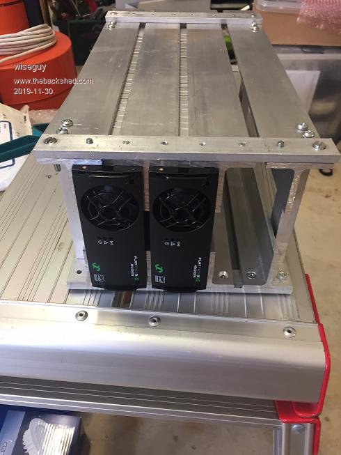 I also got back the little RM6 transformer PCB's with track windings and it works a treat. The Freq has to be upped to ~ 350kHz for the reduced turns to avoid saturation but it sure beats winding enamelled wires etc. ĀIsolated FET gate drive power supplies are a cinch now. For a 12V in supply the gate drives are all ~ 12.5 - 13V under normal load. 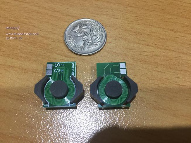 Edited 2019-11-30 23:54 by wiseguy If at first you dont succeed, I suggest you avoid sky diving.... Cheers Mike |
||||
| BenandAmber Guru Joined: 16/02/2019 Location: United StatesPosts: 961 |
The top picture is really cool the bottom picture blows my mind WOW!!! be warned i am good parrot but Dumber than a box of rocks |
||||
| Warpspeed Guru Joined: 09/08/2007 Location: AustraliaPosts: 4406 |
First assume that all of your analog and digital control system, and gate drive circuitry run from stable voltage regulated sources such as +12v or +5v. Now the power switching mosfets in your inverter just switch on and off. It could be high frequency pwm such as in an Oz inverter, or it could be at 50Hz as in a very basic square wave inverter, or in a stepped waveform Warpverter. There will be a dc input supply voltage, a fixed transformer ratio, and a resulting ac output voltage (under some fixed switching duty cycle). Ā If the dc input voltage falls to half, the ac output voltage will also fall to half. ĀIf the dc input voltage rises by one third, the ac output voltage also rises by exactly one third. ĀIts directly proportional dc input vs ac output. Now what happens if we leave the supply voltage the same, and adjust the duty cycle. If we reduce the duty cycle by 50%, the ac output voltage falls by 50%. If we have designed in some some headroom, we could increase the duty cycle and see an exactly proportional increase in ac output voltage. The usual way we control the output of an inverter is with voltage feedback. ĀWe compare the ac output of the inverter to some fixed reference, and adjust the duty cycle to maintain a constant output voltage for changes in both load and input voltage. We need to design our inverter with a suitable transformer ratio so that at the minimum dc input voltage, and at the full maximum 100% duty cycle we can still just reach the desired output voltage. At Ātwice the minimum dc input voltage, we will find that the voltage feedback needs to reduce the duty cycle down to 50% to maintain the correct output voltage. ĀSo: At minimum design input voltage, feedback adjusts the duty cycle up to flat out 100% At twice the minimum input voltage, feedback adjusts the duty cycle down to 50% We can achieve this same effect in two different ways. ĀWe can use voltage feedback to adjust the duty cycle. Or we can just measure the dc input voltage, and use that to set the duty cycle directly. No need to measure the ac output voltage, because we can predict what its going to be ! At minimum design input voltage set the duty cycle to 100% At twice the minimum input voltage set the duty cycle to 50% It will achieve the exact same result in two very different ways, but there are some hidden advantages and disadvantages in each method. The big advantage of voltage feedback is that it will correct precisely. It will gradually reduce any output error to zero. But voltage feedback has to be very slowly applied. You cannot just apply massive feedback, it will over correct, and become unstable. There is also the difficulty of measuring a constantly changing sine wave voltage. It needs to be rectified and filtered which adds an inevitable time delay. A slightly low output needs to be gradually ramped up until its correct, and no faster. Some fairly critical time constants are involved in a PID control loop. The big advantage of voltage feed forward is speed of response. ĀIf the measured dc input voltage suddenly dips by 13.2% the output can be cranked up instantly by 13.2% so output amplitude correction can be made almost instantaneous without any possibility of instability. The output voltage after a sudden change may not be precisely correct, but by golly it corrects fast. How to do it. Just measure the dc input voltage with an analog to digital converter. Design the minimum dc input voltage to be at half scale. With a nine bit converter half scale would be 100hex full scale would be 1FFhex. Just ignore the most significant bit. At minimum input voltage 00 have the pwm duty cycle set at 100% At maximum input voltage FF have the pwm duty cycle set to 50%. Is just straight line division in software. Very simple. Now there is one inherent problem with feedforward. The inverter will correct perfectly for input changes. But the output voltage is going to droop with increasing load. My own inverter drops off by almost exactly 2v per Kw of load. We can correct for that by measuring the dc input current and applying a similar feed forward correction for increasing load. In my case 1Kw is ten amps (its a 100v system). So for every ten amps of measured dc input current, I can increase the duty cycle just enough to compensate for the 2v drop. So we have an extra voltage droop potentiometer, that we can tweak to adjust the inverter output voltage when fully loaded. It could even be set to have the inverter output voltage to overcompensate and rise slightly with increasing load if that is what you wished. Its not that complicated, and in fact will probably have fewer parts because there is no requirement to measure the isolated ac output voltage, which is not that easy to do. Measuring non isolated dc voltages and dc currents is dead easy. ĀIts also fast and accurate. This is not pie in the sky B.S. ĀFeedforward works, and works damned fast with far fewer potential problems than very carefully tuned PID feedback. Edited 2019-12-01 10:16 by Warpspeed Cheers, ĀTony. |
||||
| BenandAmber Guru Joined: 16/02/2019 Location: United StatesPosts: 961 |
I wish I could understand it warpspeed This may be really a really stupid question On the China inverter boards can you get your 3 volts off of the battery side and it be voltage feed-forward be warned i am good parrot but Dumber than a box of rocks |
||||
| Warpspeed Guru Joined: 09/08/2007 Location: AustraliaPosts: 4406 |
No. Cheers, ĀTony. |
||||
| rogerdw Guru Joined: 22/10/2019 Location: AustraliaPosts: 904 |
I'm no design engineer ... but wow, that is elegant. You make it sound so easy. I had been wondering if you might also need to monitor the ac output as a secondry control ... sort of a backup measure in case the output did get out of hand ... ... but covering the known I/P DCV - O/P ACV ratio ... and then taking into account the load by simply monitoring the I/P DC current and applying your already worked out figures ... should cover voltage regulation ... and load compensation perfectly well. And as you say ... so much easier to be monitoring instantaneous DC supply voltage and current ... as against the constantly varying and fluctuating AC O/P and trying to apply feedback at the correct rate without hunting or overshooting all over the place. You probably need to delete all these posts in case the commercial boys read them and steal the idea.  Cheers, Roger Cheers, Roger |
||||
| The Back Shed's forum code is written, and hosted, in Australia. | © JAQ Software 2025 |
