
|
|
Forum Index : Electronics : MPPT software suggestion in pseudocode
| Author | Message | ||||
oztules Guru Joined: 26/07/2007 Location: AustraliaPosts: 1686 |
Thanks for your explanation Gill. (Gizmo, just don't read this thread for a bit until we get this part out of the way) I don't have a unzipper in my linux box, so was unable to open the zip file re: mppt. However, I think I know what you are referring to. My initial understanding goes something like this... (please point out the differences if you feel that it is useful) : Max power tracking is a term used by folks to refer to using pwm and some form of fuzzy logic (I think it may be called) to achieve the maximum amps into the battery that the system is capable of delivering in any particular wind environment. or in the case of solar, light source. My thoughts on this.... For solar this is pretty straight forward as there are no slippery components in the system, just a high impedance voltage source, which is affected by incident light. This is simple to operate with, as the variables are simple to understand. Lots of companies make these, and so could I. The problem comes about with wind because people use the same analogy to wind as to solar with regards to mppt. It appears that lots of folks that have a handle on the solar system, have gone out and tried to develop a wind mppt along similar lines.... and it just has not worked. It is to this effect that I find it necessary to broaden my horizons, and look carefully at the system as a whole. With wind turbines, nothing is independent, all things seem to interdependent, and it is this property that will stop mppt from becoming realistic if we don't broaden our definition to take into account all things that contribute to the mill giving the maximum transfer of available shaft power, into the battery bank. To me, it matters not what we call it, but how we understand and use it. We want max amps into the battery for any given wind speed...... what should we call this holistic approach if not loosely under the banner of mppt. To this end let me take us back to your variable pitch. If we use it we don't need mppt, it does the same job as mppt would have but by totally different mechanisms. At this point it becomes necessary to bring in an accepted definition of mechanical impedance. (goolge should pull it up straight away) "Mechanical impedance is a measure of how much a structure resists motion when subjected to a given force. It relates forces with velocities acting on a mechanical system. The mechanical impedance of a point on a structure is the ratio of the force applied to the point to the resulting velocity at that point. Mechanical impedance is the inverse of mechanical admittance or mobility. The mechanical impedance is a function of the frequency of the applied force and can vary greatly over frequency. At resonance frequencies, the mechanical impedance will be lower, meaning less force is needed to cause a structure to move at a given velocity. The simplest example of this is when a child pushes another on a swing. For the greatest swing amplitude, the frequency of the pushes must be more-or-less at the resonant frequency of the system." Acoustic impedance is another form of impedance, and likewise has no electrical components associated with it (although I have developed motional feedback speaker systems/amplifiers that try to manipulate it using accelerometers built into the cone with corresponding compensation.... sort of maximum acoustic point tracking to match the wrong speaker to the wrong acoustic cabinet to get the right acoustic result. Phillips and Sony did the same kind of thing as I recall) However, all that is less than useful to spend our time on, the thrust of the argument is of more import than the pedantics. I feel that the variable pitch is a torque converter/impedance matching device (mechanical) whose electrical equivalent is what your mppt is trying to achieve.... do we agree here? If not, what is the purpose of variable pitch if not to match the load? Next we look at this, "If I had a 2" wind pump and changed it for a 21/2" and it stalled the blades, I could a. vary the blade angle b. reduce the load by changing to say 21/4" or back to 2" or of course c. reduce the crank length so the stroke x volume is bought back to the original equlibrium of the 2" pump and carry on using the oversize pump.... ie we match the load. (If we could change the crank point radius on the fly, we could have mechanical load matching for all windspeeds.) If you look at the pumper pictures I posted recently, you just miss seeing the extra holes in the large gear to do just this. This to me is another example of "mechanical" impedance matching.... I think I have just about done this impedance thing to death. If we wish to call this mechanical impedance matching something else in order to gain some common ground, I am well prepared to call it anything you wish, because it is critical to take these events into account so as to design a decent pwm signal to achieve the coveted mppt. I still think that impedance is both correct and useful. It also makes electrical impedance matching more respectful of the mechanical matching that must go hand in hand. I have no doubt that Gordon and a host of other very clever people would have achieved accurate and successful digital mppt, if it was only an electrical problem of impedance matching that they were tackling. I think there is more to it. I don't know the answer, thats why we are having this discussion in the first place. However, I do know that power quotient will increase under Doms chopping exercise (perhaps not very well with the proposed code but a start point... it may do well) . I do know that amps into the battery will increase with resistance in the line, if the alt is too stiff (electrically) for the blades (aerodynamically). This effectively increases the impedance of the battery pack, and so gives us a better match. I know that changing from star to delta will help improve matching as the rpm increase beyond a certain point where emf-cutin volts sq/r in star becomes less than emf-cutin volts sq/r in delta. r in Delta is 1/3 r in star. I also know that if you design for star, but wire in delta, your cutin goes higher, but your match to the power curve of the prop to the curve of the alternator becomes much better, and that if you design for say 24v, but drive 48v batteries, the curves will be so much better that mppt becomes a marginal thing, and a boost converter for pre-cutin purposes will suffice for all but the purists. It hasn't been solved thus far, and this makes a technical definition for mppt, a moot point...no one seems to have it. So far it's just a goal (like finding higgs bosuns) It's the goal that counts The fact that the big boys havent gotten to market with a turnkey model one size fits all yet speaks volumes. There may not be a definitive answer. It may be that for us mortals, a combination of a few tricks with a limited pwm component may do the trick.. However, on the bright side, the complexity of the physics involved is such that you can effect some positive outcomes for modest inputs, (load resistor springs to mind here), or designing for high cutin speeds (with neo's) or moderate cutin speeds for ceramic magnet/iron alts. This tactic will better match the squared/cubed graphs when cutin is achieved anyway, but you spin the blades for no output in lower winds. This is probably a good tactic total KWH wise, but it feels good to make something most of the time rather than lots some of the time, so is rarely done.... and it's noisier than stall based systems. As an aside,I do the electronics and electrics on two mid sized mills down here. They put out in excess of 300,000,000 watt hours annually. These are matched only by the grid tie, but takes a fair wind to start them, so when they get up and go, their power curves match the wind reasonably well, ie the bendy part of the graphs is below cutin, and the longer straighter parts of each graph superimpose fairly well. The reason I mention these is that with no mppt, they track very well. They are fixed blades. There are big winds over here tonight, and they will be putting out well over 100KW at the moment So we seem to build the little ones to start too soon, and we need a fix for that. So what I am getting at is that we need to be cognizant of all factors at work, and how a simple change in one will effect others that we didn't consider. We may make a change which changes something else, that masks the fact that what we see isn't actually caused by what we thought.... here the garbage in = garbage out comes into play. What we changed and works for one part of the power curve may not necessarily work for another part of the power curve, because what we thought we were effecting, we weren't, but got those results for different reasons, so if this part makes no sense, then it is supposed not to, as that is what we face apparently. Thanks Gill for taking the time to read this response. If you still feel I'm errant, it is because I really do think I have tried to get the feel for what is happening up there, just haven't gotten around to doing anything about it yet. Hopefully, Dom will get something out of this screed and your responses, that will crystalise something in his mind that will break his present impasse. Don't think that simple pulse chopping will only effect output negatively because it makes sense that way. In the real world A changes B,which changes C, which turns into a pumpkin... There will be situations where turning it all off for brief periods will allow TSR,WS,attack angle inertia, backemf and the wind gods to conspire to increase output current instead.... ie blade speed increases, and the whole thing runs freely. It may not fit your MPPT definition, but may achieve the same thing by other means..... does that mean it is not a form of mppt? .........oztules I've rabbited on enough I think for now. You can always ask me to butt out at any time, as I know I talk too much sometimes. Village idiot...or... just another hack out of his depth |
||||
| domwild Guru Joined: 16/12/2005 Location: AustraliaPosts: 873 |
Have found something, which is rather complex and here is the link: http://www.iceo.be/abstracts/pdf/servlet01cgi/ewec.php?id=65 0 Title is: "Maximum Power Point Tracker For Small Wind Turbines Including Harmonic Mitigation" A single-switch three-phase single-ended primary inductor (SEPIC) rectifier is driven via PWM. A SEPIC rectifier behaves like a buck/boost DC-DC switcher. RPM, volts and amps are measured. The RPM are used as an input into a look-up table containing the max. power. Output from table is active power for one phase. Volts times amps gives watts and after filtering the DC power part is obtained. (I am not clear on this first-order low-pass filtering). Both power signals are subtracted to give an error signal which drives the PWM. How the components of the SEPIC are calculated, such as the input inductor, is stated in a master thesis given in the references. Claims: 27% more power compared to bridge rec. connected directly to batteries. I hope I have "abstracted" the info in this document correctly for all those who may not wish to download this document (10 pages in pdf format). Academia is certainly chasing this wind MPPT problem. After reading a paper on SEPIC DC-DC switchers with complicated formulae I realise it is complex. Taxation as a means of achieving prosperity is like a man standing inside a bucket trying to lift himself up. Winston Churchill |
||||
Gill Senior Member Joined: 11/11/2006 Location: AustraliaPosts: 669 |
oztules, Well I slowly read your response and didn't find anything that I would disagree with as it is the same as I have been saying though I prefer engineering terms such as load and resistance for mechanical power transfer as opposed to impedance and acceptance which are electrical terms. But knowing this difference in expressing the same thing helps. 
I see you don't grasp what I have been saying about the two distinct power tracking areas, how they can be addressed individually or how the last could possibly be made to address the first. You lump it all together with little structure or reference as I see it. I guess we all present our ideas and see if it clicks with others. That's a lot of what forums are about. With my mill under construction I'll be adding to it's masthead phase controller the PWM switching of Dom's. I think a high angle of attack of 10 degrees giving a negative tip angle is needed with the PWM switching. As Gordon says "we over power our mills". I'm maximising both areas then, one in 5 x phase step the other by PWMtracking. Not full tracking of the gen to battery power, but stepping will do until something better comes along. was working fine... til the smoke got out. Cheers Gill _Cairns, FNQ |
||||
| GWatPE Senior Member Joined: 01/09/2006 Location: AustraliaPosts: 2127 |
Hi All, thanks to Oztules for a great read. My understanding is, what is needed is to extract the max power from the available wind energy during any interval. It is that simple. The type of generator and the rotor blade area will limit the effectiveness of a maximizer. A maximizer will not allow a low power, coggy generator with a 3m dia rotor to extract 1000W from 10m/s wind. A variable pitch solution can only work on an overloaded design, ie one with a low cutin speed. I cannot see how pitch control can give a four or more fold increase in voltage and maintain a TSR and still produce generator volts. I have decided to adapt my code to a buck design. I have a spare pcb that I can make into a buck topology. I can operate my power supply to give 60V@3A. This should be good enough for testing. If I can achieve a cubic output current that is proportional to input voltage, then this will work. Gordon. become more energy aware |
||||
| Gill Senior Member Joined: 11/11/2006 Location: AustraliaPosts: 669 |
Gordon, Sorry you don't see the value of the variable pitch prop or how it could compliment the area of your work. I doubt the cubic like current output is an indication of a holistic tracking of the wind power through to the battery. Doesn't the buck converter take the excess voltage and convert it to current which when combined with the otherwise linear current, make a cube like current? All from available power and not from additional power from the wind? Still, I seem to be out on my own with no understanding / acceptance of what I was trying to get across. Never mind, I'm still incorporating that thinking into my own deigns. I see all the work going on as worthwhile so we're all winners for sure. was working fine... til the smoke got out. Cheers Gill _Cairns, FNQ |
||||
| GWatPE Senior Member Joined: 01/09/2006 Location: AustraliaPosts: 2127 |
Hi Gill, I see variable pitch as similar to mechanical furling as a protection mechanism for high winds. In all of my designs the wind is the only source of power. My test windmill has no excess shaft power. The blade area at maximum wind velocity can only capture 500W of shaft power. If the same generator had a 3m rotor, then this combination would be classified as overdriven. This is how I see most F&P DIY windmills with a 3m rotor. Indeed this will be what I expect my std F&P 100S with 3m rotor will be like. The exact input/output relationship does depend on blade efficiency, generator efficiency, startup torque, bearing loss, rectifier loss, electronic conversion and wiring loss. I am fortunate in that my Lakota blades are pretty efficient, my axial flux alternator is very efficient and has negligible startup torque, I have used a low loss rectifier, I have special low friction bearings in the mill, I have a short wiring run with thick wire and the electronics are low loss. I have seen a good correlation between measured wind velocity and rotor RPM and mill output power to calculated wind energy. For my setup I currently can extract the power from the available wind energy of < 5W, all the way up to approx 450W. This is from a windspeed of 2m/s up to 10m/s. with a 2m rotor dia. I will be happy if I get similar bottom end power, but lower top end power from my 3m F&P mill. I do expect to get approx double the power in the middle part of the wind energy, up to about 250W of wind energy. This would be entirely due to the double the swept area of the rotor. At this point I expect the F&P mill output will plateau, due to mechanical components. The point of my exercise is to match my windmill to the winds I get 80% of the time and still have all the systems survive when the wind gets over 30m/s. On a separate point. I see the main problem with a MPPT regulating type approach is that with a windmill, there are no constants. With solar there is the relatively constant panel voltage at the MPP. With hydro the water head is pretty constant. My code has no regulating function as such. The code predicts the required pulsewidth and avaerages with the previous value to calculate a pulsewidth that is then used in the next calculation. There is no automatic ramping of the pulsewidth to try and find a maximum power level. This is the only way I was able to eliminate Ocsillatory behaviour in the control system. Gordon. become more energy aware |
||||
| domwild Guru Joined: 16/12/2005 Location: AustraliaPosts: 873 |
Sorry, picked up a wrong link for the same article. Here is the one I mean and after posting i will try it out this time: www.ewec2006proceedings.info/allfiles2/846_Ewec2006fullpaper .pdf Taxation as a means of achieving prosperity is like a man standing inside a bucket trying to lift himself up. Winston Churchill |
||||
| domwild Guru Joined: 16/12/2005 Location: AustraliaPosts: 873 |
By mistake during copy/paste there is a blank after paper and .pdf. Sorry. Taxation as a means of achieving prosperity is like a man standing inside a bucket trying to lift himself up. Winston Churchill |
||||
| Gill Senior Member Joined: 11/11/2006 Location: AustraliaPosts: 669 |
Dom Gordon and crew, I see from the article they lump all in together as MPPT too. I guess I must accept this from now on, if somewhat reluctantly.  was working fine... til the smoke got out. Cheers Gill _Cairns, FNQ |
||||
| GWatPE Senior Member Joined: 01/09/2006 Location: AustraliaPosts: 2127 |
Hi Dom, The link above states a buck/boost terminology. My understanding is that a buck cct, converts volts to an increase in amps. A boost cct converts amps to an increase in volts. I will look at this a bit more later, when I have some time. It looks promising. The capacitor C2 passes all the AC. There is no DC path to the load. Inductor and capacitor sizing will probably be critical. Gordon. become more energy aware |
||||
| oztules Guru Joined: 26/07/2007 Location: AustraliaPosts: 1686 |
Well Dom, To me it seems these electrical engineers have not actually used a windmill. Their mppt technique may work for an induction motor (which they use for their angular speed being derived from their induction controller and motor shaft speed (figure 12) but I fail to see how they are going to equate the real world to these artificial results. Garbage in garbage out will bring this undone if they intend to use prop speed as their angular speed. It fails to understand why the shaft speed is what it is. ie is it say 100rpm because it is in stall, is coming off a gust, is slipping in tsr and should be higher.... etc. They assume that the 100rpm shaft speed, means that a certain windspeed is available and use the jump table on this premise. Rubbery figures when you don't have an induction motor driving the thing. If it was that easy (measure shaft speed, quick error signal from power1-power2), we'd all have one. .........oztules Village idiot...or... just another hack out of his depth |
||||
| GWatPE Senior Member Joined: 01/09/2006 Location: AustraliaPosts: 2127 |
Hi oztules, fig 13 tells a much clearer picture. The step response. They used a simulated change in windspeed from 10-12m/s. The controller took aver 4 seconds to reach 70% response. The winds I have to contend with at my home are reasonably turbulent, with gusts that may range from 4m/s to 8m/s in 2-3 seconds, up and then down. The electronics cannot add any significant response time to the system. I see this controller may only work where the wind is pretty constant, or in a controlled test environment. This is not much use where I live. Gordon. become more energy aware |
||||
| GWatPE Senior Member Joined: 01/09/2006 Location: AustraliaPosts: 2127 |
Hi readers, I have posted a graph showing real time Maximizing, and the response time that needs to be achieved, to capture the energy in a gust of wind. 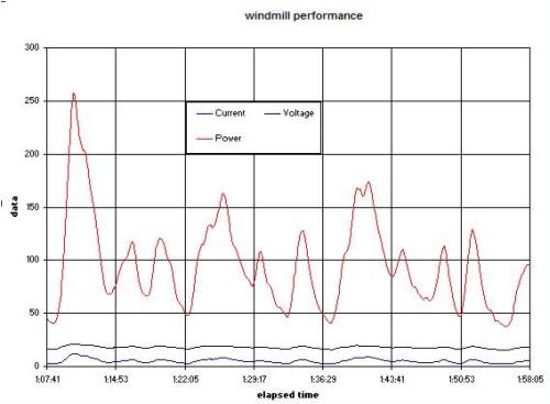
Between 1:08:00 and 1:13:00 on the graph, the maximizer had to follow a wind gust. This was a transient from 45W to 250W and back down again, in a 5 second window. This cannot be achieved with the MPPT example provided in the link presented in a posting above. I have scale expanded the windmill voltage and current for the same time period and graphed it. The upper graph is the voltage and the lower is the current. 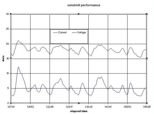
This power is charging my 24V battery, whenever the current is greater than zero. The battery was at 27.6V, so you can see how much of a range of voltage and current that has to be converted to a current and voltage the battery needs. The battery voltage [not shown] was being held relatively constant by the gridfeed cct that supplements the base load of my house. I have struck a few glitches in the picaxe code I am developing for the O8M chip. The code did not correctly load the windmill at power levels above 150W. I could not test this level on the laboratory power supply I use. I am working on a modifier to correct this. At the same time the code has to compensate for different battery state of charge voltages as well. I have to write 2nd and 3rd Order Poloynomial modifiers, that I will still have to test. As Oztules has said, an idea can seem to work on a simulator or test rig, but until the real world windmill experimental test is proven, you may have nothing. .. .. Gordon. become more energy aware |
||||
| domwild Guru Joined: 16/12/2005 Location: AustraliaPosts: 873 |
Oz, If I understood your critique correctly, then this sentence from the report may clear it up: "Some control strategies are based on the power coefficient curve (cp), e.g., TSR control method, which modifies angular speed of wind rotor for maintaining an optimum TSR value ..." "To the small wind turbine used as reference .. the angular speed for max. mechanical power does not coincide with max. electrical power so this method is not recommended." They have simulated the max. mechanical and max. electrical power using a dynamic wind turbine model for this 400 watt turbine. So they "know" the RPM figure vs. watt figure which is entered into the look-up table. What is actually coming off the mill minus the table value is then the error signal to the PWM. However, my knowledge (knolege is power!) is insufficient to argue for or against those boffin's ideas. Flux has put his ideas on fieldlines to this article. The US government has given NREL (Nat. Renewable Energy Lab.) a grant to develope a tracker for mills. Gordon: Re gusts and the PIC following with error signals. Isn't this just a case of sampling more frequently with a faster PIC? Taxation as a means of achieving prosperity is like a man standing inside a bucket trying to lift himself up. Winston Churchill |
||||
| GWatPE Senior Member Joined: 01/09/2006 Location: AustraliaPosts: 2127 |
Hi Dom, I have looked at the SEPIC converter. Re: a SEPIC converter. The pulsewidth has to start with a high duty cycle when the input to output voltage ratio is low. I have yet to explore what is needed beyond this point. I expect that the pulsewidth will be 50% when input voltage = output voltage. I will have to make a unit and see what happens. I have to look at what happens to the flyback energy as well. My intention is to use the tools currently that I have access to. I imagine that someone who has intimate understanding of Assembler, or C++, and a PIC can re-engineer the code I have almost perfected for the picaxe. I still have to test my lastest code revision on my windmill. Wind was a bit scarce today. I have compared the loading curve for a buck design, and it is much easier than the boost to track. This is probably why this is a good system type for developers to look into. The boost design has an inverse control relationship, while the buck is a proportional type. The SEPIC is supposed to be more complicated. Re: Gordon: Re gusts and the PIC following with error signals. Isn't this just a case of sampling more frequently with a faster PIC? In my control system, I do not refer to an error signal. This is jargon used with a system that performs a regulation function. My current system relies on a single digitally averaged measured variable. This is a "direct" control system. All I need to know is the minimum desired cutin generator voltage and the nominal battery voltage and the maximum expected windmill power. I have developed a spreadsheet that formulates a loading curve, and this is programmed to the picaxe. I have adapted the spreadsheet to formulate for a buck system as well. If I had a 20A@50V variable laboratory power supply, I could test without a windmill. The PCB I have made is a good layout for the boost design, so I will look at a new layout for a buck design. A windmill is not really a complicated machine. I see a few variables, that I do not measure, that will change windmill blade performance, one is air viscosity, and another is blade wear. These will change the efficiency of the blades and hence available wind power. I will ignore these for the moment. I have deliberately avoided the term MPPT, I rely on the windmill inherant predictable features and maximize from that. I have also lowered the minimum windmill cutin voltage from 8V down to 6V. This may not seem much, but this will probably be a good point for my F&P machine. cheers, Gordon. become more energy aware |
||||
| oztules Guru Joined: 26/07/2007 Location: AustraliaPosts: 1686 |
Dom, Thanks for the information, but it changes nothing. (for me anyway) Why is this so I hear you ask in your relentless search for truth...... Well, I could be just plain wrong. The way I see it is this, they state the obvious that the wind power curve and the alternator curve are different. "To the small wind turbine used as reference .. the angular speed for max. mechanical power does not coincide with max. electrical power so this method is not recommended." Lets have a look at this first: The EMF (electromotive force) in the alternator rises linearly with RPM. This is set in stone, so I consider it a thing I can rely on. The measured voltage is totally different and is held to ransom by the resistance in the alt (air core here, inductive iron core are more complicated) and the impedance of the load hooked up to it. We will assume batteries here, so mostly resistance, with line losses and non-linear diode behaviour just mess it up some more. If we care to make this simple, we can say that as the RPM rises, the emf rises linearly with it. The power therefore will be the EMF (which you can work out in a no load situation, and graph volts to revs) minus the cut in volts, squared, and divided by the resistance. So power in the alternator can be seen to be a squared function to speed. The wind makes the rpm change linearly. As we double wind speed we expect a doubling in rpm. The power available is 8 times or cubed to speed. So it's no secret that the curves are different. One is a square function, one is a cube function. I know that was a waste of typing, because you already know this, but I am stepping through this so you can see where I go haywire wrong, or why I may be correct. I reckon we will agree up to this point. Now it seems logical at this point to jump right in and say "They have simulated the max. mechanical and max. electrical power using a dynamic wind turbine model for this 400 watt turbine. So they "know" the RPM figure vs. watt figure which is entered into the look-up table. What is actually coming off the mill minus the table value is then the error signal to the PWM. " And if it wasn't a wind system, you would sway me as well Well maybe but it does not tell us how much power is in the wind at this same instant..... why not, we have the output power, we have the prop speed, we know what we should be outputting, we beat the values and we should have a difference signal to feed to the pwm device... we should be good to go, at this point they think so. So what is the instantaneous TSR at the time of measurement. We now have the RPM, but what is the incident windspeed the blades are seeing, how are they transferring that to torque and shaft speed?? Well they don't say. If we don't know the tsr, we can't calculate the wind speed, and if we can't calculate the wind speed, then the jump table means very little.... why do I think this? If we have say 100rpm shaft speed, and we have a wind curve for a properly loaded turbine, we can look up the tsr and calculate the wind speed and so available power. Our model jump table should be enough to give the correct error signal to use this power quotient up. So it should be simple.....well not quite. What if the blade is not ideally loaded? What is the tsr then, and what is the windspeed... remember it's a cubic function so a little wrong can be a lot wrong to the jump table. What if a gust has come along, does the tsr go up slow enough to track it, or do we get crazy figures and overcompensate going up, and do the same coming off. What if one of our previous errors puts us into stall (4 secs will do here). How do we get out of stall, or do we stay in stall. Do we beat this? by under loading it any where around stall? Worse still, what if our furling is working, try and guess how the tsr will look to output now, Shaft speed to output will bear almost no relevance to windspeed. We have to guarantee to come out of stall (because the jump table will have trouble with the furl curve) and how to compensate, coming out of furl. What if we are overloaded from a previous poor guess, or underloaded from same, Recovery should be logical, but we turn out to be way way out of step with the events as they unfold because of 4 sec delays to poorly catch up. This kind of delay is an eternity for wind turbines. (as Gordon also pointed out "fig 13 tells a much clearer picture. The step response. They used a simulated change in windspeed from 10-12m/s. The controller took aver 4 seconds to reach 70% response.") So we don't have a hard figure with which to place wind speed and so, trust to best guess. It turns out that initially best guess is 4 secs for 70% getting close ... behind the game already, how long to be completely confused. Can it recover from this.... 4 seconds of steady wind is possible, but longer is not probable. Looking at the AWP zipping around in the wind today, maybe 4 secs tops, 1000 feet above the landscape in pretty clean wind. So like I said, I may be wrong, but to me the figures are embedded in quick sand. I have looked at this from every which way, and don't see an answer short of an axial wind flow meter built into the front of the hub of the turbine to see the wind speed it sees, in the axis it sees, and THEN you can jump table in real time. This should be a simple analogue setup. But I have not bothered yet. Maybe one day. After years of watching this mppt space unfold, I don't see any simple calculated fix from watching the watts out and making an informed decision based on rpm. Because every decision we make, effects the input/rpm, which affects our decision, which affects the output... and around we go again. The system linked to uses the same flawed logic. The last bit of evidence to scrape up off the floor..... this is a 2006 paper, Outback and others have been working on this since then as well.... still nothing I know of to date, and haven't heard of any Brazillian mppt millionaires yet. The sepic may produce some gain in alternator efficiency if the switching harmonics of the diodes can be mitigated some. Do the sums on the power factor, unless it gets below 80%, it will be one of your lessor losses. Otherwise, just a boost or buck will be sufficient. I am a firm believer in Flux's idea of a precutin booster and make the curves match after that. No mppt required to get an mppt type result. Simple, idiot proof, and almost failure proof. I suppose it's true that PF will be better whilst boosting before normal cut in. I designed and built a 600w booster in a day, and it seems more than big enough to do the job, simple and if it fails, it does not effect the mill or the majority of the output. It could be built better but it was just a test of my second booster project to learn a bit about that topology. It is not rocket science at this power level..... and if it does fail it is not mission critical. Well thats about it I think Dom, It looks good on paper.. until it tries to control a real windmill. Any torque converter they used would have to be a very sophisticated device to mimic the wind/turbine/load character.... and furl etc. Especially on an induction motor. .........oztules Village idiot...or... just another hack out of his depth |
||||
| GWatPE Senior Member Joined: 01/09/2006 Location: AustraliaPosts: 2127 |
Hi oztules, I agree with your reasoning. Any control system that measures and compares and calculates and tries to adjust a pulsewidth to a control element where there is a time lag involved will become unstable. I remember from my Uni days a subject "process dynamics and control". The way to achieve better control is to increase the size "capacity" and increase a dampening element. To attempt this on a windmill would mean the system would miss the peak powers as the blade efficiency is so much dependent on tsr, and overloading may cause a blade stall, and the system falls over. This is akin to foldback current limiting on a power supply. The only way to restore output is to remove the load. As a separate exercise, the power transfer properties of the electronics is highly dependent on the load. In a system with batteries, this is very critical as the battery presents a high load when charging. The terminal voltage is also SOC and charging current dependent. This problem has caused most of my early designs to only work at a particular battery voltage. On a more brighter note. I have completely redone my picaxe code and now have adopted pulse frequency modulated, pulse width modulation. This has exploited a design property of the picaxe micro interpreter, when used to produce a PWM output. The latest revision has allowed the generator cutin voltage to be dropped a further 1V, to 5V. This has meant that my data logger cannot be inserted between the mill and maximizer, but has to measure the battery voltage and current after the maximizer. This graph is a typical output from a wind gust with the new code. the green line is Battery volts the white line is windmill power [x10] the blue line is Battery charging current 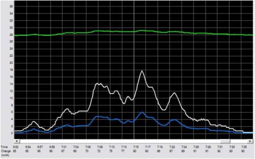
the maximum power occured at a windmill current of 11A and a windmill voltage of 17V. The lowest power was 1W at a windmill voltage of 5V and 0.2A This gust would not have been captured if the windmill was directly connected to the battery, ie, without the maximizer. The gust occurred over a 30 second time window. There were at least 4 separate mini gusts components, and I can see no oscillitory behaviour of the control system. This is probably because there is no feedback system or error correction, or delay lags. This was sampled at 0.2second intervals. I will have to make a new logger, that can log current and voltage from 0 to 30 at up to 100 times per second, that is not powered from the windmill. This will measure 4 parameters, windmill current and voltage and battery current and voltage, so the performance of the electronics will also be seen. This new unit loads the windmill almost the same as my analogue unit. The cutin voltage is now 3V lower as well. I will have to wait for more stormy weather to check the top end performance. I will publish some more test data later, as it becomes available. I will have to look into a way of making the code universal, so it may work on a F&P, or other windmill. Once this is achieved, this will fill a windmill performance gap. .. .. Gordon. become more energy aware |
||||
| Gill Senior Member Joined: 11/11/2006 Location: AustraliaPosts: 669 |
For problems of lag, the beauty of PWM is there is no rule which says one must stick to the lowest unit of adjustment. If your pulse width cannot keep up when incremented by one then change it to increment by 10, 20, 50, or even 100. With the slowest PWM frequency at 4,000 cycles per second I think that is plenty fast enough with the correct increment. was working fine... til the smoke got out. Cheers Gill _Cairns, FNQ |
||||
| Gill Senior Member Joined: 11/11/2006 Location: AustraliaPosts: 669 |
G'day all, I don't like the idea of having to number crunch a look-up table. Besides being too heavy a load on the brain, it is not suitable for a variety of configurations of generator and prop types without again more research and heavy number crunching. Maybe OK for commercial production where hundreds of the one type are made, but stifling for DIY variety, adaptability and inventiveness. As a flow on to my earlier thoughts, here's what it looks like as it comes together. But first, NOTE: I must stress, for this system the mill must be designed to be underpowered until its peak (just before furling). It does not suit retro-fitting to existing mills without prior blade adjustment (shorter blades with reduced blade angle for higher TSR). 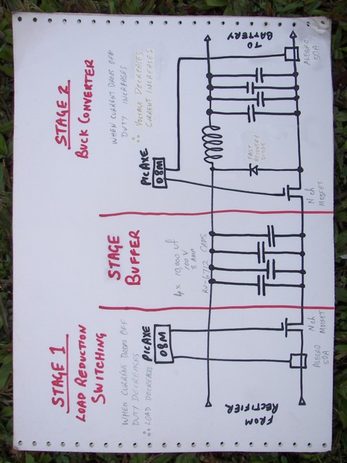
The MPPT is a 2 stage type. Each stage carries out a distinct and separate function. In both cases amps are monitored and the Pulse Width adjusted to peak the amps. This tracking and adjustment to peak with an ever changing wind, makes this MPPT suitable for any machine (see Note above) and does not require look-up tables that is individualised and a substitute for a missing first stage. Stage 1. The function of this stage is to cause the shaft power to track the wind power instead of the velocity as it does on our setups now. Whilst achieved by the variable pitch prop which adjusts the pitch to a coarser angle (lower TSR) to avoid stall, and so by prop gearing, match the fixed wind power to the fixed gen load. This method allows the fixed wind power through a fixed pitch prop to match the varied load of the generator. With the wind power matched to our gen(load) power at peak rpm. Most lesser rpm has the generator load power more than the corresponding wind power because of the fixed prop with it's fixed TSR. By reducing generator load the mismatch is eliminated. The gen loading at any rpm is reduced by repeated disconnecting the battery for microseconds. This tracked point sees a peak in Amps and Volts out of the generator. Now the Volts and Amps follow the wind power instead of the wind velocity. Stage 2. Now that we have a generator with Volts and Amps that track the wind power, it must be applied to a load. If a resistive load like a heating element, nothing further need be done. For battery charging, after cut-in is achieved, the excess volts go to heating the stator coils and rectifier and are lost to our battery. We can recover this lost potential and convert it to even more current. Here I've used the the simplest form of Buck Converter(because I'm dumb with limited knowledge) to do this task. I imagine Solar MPPT are designed to a more sophisticated standard by the professionals. Whilst they do the same task of this second stage, Solar MPPT do not have to contend with the much higher range of voltages delivered by a wind generator. The result of buck conversion is that the Amps through the freewheeling Diode sub-circuit and the Allegro Current Sensor are higher than those of Stage 1. The monitoring of these amps by the PicAXE allow it to adjust the pulse width to a peak and ever changing value. An even better understanding of Stage 2 can be had from this ZIP. 2008-06-28_145343_MPPT_Technology_.zip Stage Buffer. Due to the very important Independence of switching in each stage, the OFF state of one cannot be allowed to interfere with the ON state of the other. To ensure this is so a large storage capacity is inserted between the stages to buffer all conflicting switch states. Code. The code for both PicAXE are almost identical but opposites. I've chosen 20,000Hz as the Pulse frequency thinking to make components more readily accessible. Though I fancy 1,000Hz for Stage 2 as it is the desulphation frequency. A PWM code would need to be specially written as that Fq is well outside the PicAXE's PWM function. Perhaps component selection will ultimately dictate what will be finally used. Code: 2008-06-28_145454_MPPT_Stages1_&_2_v1-0.zip So there is Wind MPPT as I see it coming together for me. I feel I have the concept right. Now all I have to do is select the right components. Send search party if nothing more is heard as I disappear into the mire. If it ever gets finished, who knows. If I can take some of the complexity and techno jargon out of the word MPPT some measure of success is achieved. Gill EDIT: Code has been updated to v1.1 to overcome some errors. Sorry bout dat. 2008-06-30_133712_MPPT_Stages_1&2_v1-1.zip and a further update for those wanting supa fast tracking of supa fast wind gusts: 2008-07-04_223505_MPPT_Stages_1&2_v1-2.zip was working fine... til the smoke got out. Cheers Gill _Cairns, FNQ |
||||
| Gill Senior Member Joined: 11/11/2006 Location: AustraliaPosts: 669 |
News is that MidNite Solar(former design engineers with Outback) in Arlington USA are soon to test a beta version of a wind MPPT the 'MidNite Clipper'. Looking forward to any reports on how it goes. Link was working fine... til the smoke got out. Cheers Gill _Cairns, FNQ |
||||
