
|
|
Forum Index : Microcontroller and PC projects : Getting started with STM32L476 ARMMITE
| Page 1 of 2 |
|||||
| Author | Message | ||||
| vincenthimpe Regular Member Joined: 14/10/2018 Location: United StatesPosts: 86 |
I got the nucleo board flashed and managed to get the command prompt but i am running into all kinds of problems. The documentation on this thing is abysmal. You need to read 3 different documents , untangle ST's poor schematics, untangle the hat project from waveshare, untangle some other project just to figure out how to wire up something simple like an lcd display. So , to make people's life a bit easier : here is a jumpstart guide. I will amend this as i progress and untangle more of the spaghetti. Before we begin --------------------------------------------------------------------------------- 1) Make sure you have a NUCLEO STM32L476 board  https://www.st.com/en/evaluation-tools/nucleo-l476rg.html https://www.digikey.com/product-detail/en/stmicroelectronics/NUCLEO-L476RG/497-15881-ND/5347711 2) Go to ST website and download the flashing tool https://www.st.com/en/development-tools/stm32cubeprog.html The file you need is all the way at the bottom of the page STM32CubeProg. I used version 1.4.0 The first time you attempt to download things from their website you need to register with an email adress. Unzip the archive and deploy the version for your operating system. 3) Get a terminal emulation program. I use Putty ( i know, not the greatest, but free ) https://www.chiark.greenend.org.uk/~sgtatham/putty/latest.html Once we got that all installed it is time to plug in the nucleo board to a USB port and let the operating system load the drivers. 4) The documentation you will need - MMBasic Manual MMbasic - ARmmite manual 5.05.03 - LCD panel information LCD Panels - ST Nucleo L 476 Schematics (Altium format , but has PDF file in it) L476 Schematics 5) flashing the Basic interpreter 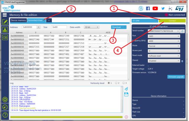 Open the STM32Cubeprogrammer (1) click the 'connect' button top right to connect to the board (2) click the 'open file' tab and select the image file ( i used the .HEX file provided in the distribution ) (3) click the Download button and wait for programming to complete. (4) click the disconnect button top right ( same as the connect button ) 6) Find out to which com port the board has attached itself. 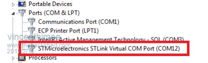 Open device manager (windows) and under 'ports COM & LPT' look for STMicroelectronics STLINK Virtual COM port. Mine was COM12 Fire up Putty ( or your preferred terminal program. ) Connect using the COM port you found, 34800 as baudrate , no parity , 8 databits , 1 stop bit : 34800,n,8,1 It is important to set up the backspace character correctly to CTRL-H for the command line to be editable. 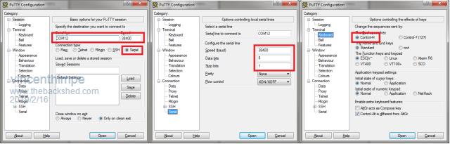 in the above image i have set my com port (COM12) , serial connection , 38400,8,1 and the Control-H character for backspace. You can save this to Putty Defaults, or a custom setup file so you don't have to do this every time 7) hit the reset button on the nucleo board and you should be greeted by the Copyright messages and a prompt. ARMmite L4 MMBasic Version 5.05.07 Copyright 2011-2018 Geoff Graham Copyright 2016-2018 Peter Mather > In order to easily manipulate I/O pins you can use this set of constants i created. This gives you access using the port names as opposed to chip pin numbers [code] ' Port definitions for STM32L476 - 64 pin TQFP Const PA0 = 14 Const PA1 = 15 ' PA2 console TX ' PA3 console RX Const PA4 = 20 Const PA5 = 21 Const PA6 = 22 Const PA7 = 23 Const PA8 = 41 Const PA9 = 42 Const PA10 = 43 Const PA11 = 44 Const PA12 = 45 Const PA15 = 50 Const PB0 = 26 Const PB1 = 27 Const PB2 = 28 ' not sure if this is functional yet Const PB3 = 55 Const PB4 = 56 Const PB5 = 57 Const PB6 = 58 Const PB7 = 59 Const PB8 = 61 Const PB9 = 62 Const PB10 = 29 Const PB11 = 30 Const PB12 = 33 Const PB13 = 34 Const PB14 = 35 Const PB15 = 36 Const PC0 = 8 Const PC1 = 9 Const PC2 = 10 Const PC3 = 11 Const PC4 = 24 Const PC5 = 25 Const PC6 = 37 Const PC7 = 38 Const PC8 = 39 Const PC9 = 40 Const PC10 = 51 Const PC11 = 52 Const PC12 = 53 Const PC13 = 2 ' not sure if the following are functional Const PD2 = 54 Const PH0 = 5 Const PH1 = 6 ' --------- Analog inputs -------- Const ADC1 = 8 Const ADC2 = 9 Const ADC3 = 10 Const ADC4 = 11 Const ADC5 = 14 Const ADC6 = 15 ' ADC 7 and 8 do not exist as they are dedicated to the console uart Const ADC9 = 20 Const ADC10 = 21 Const ADC11 = 22 Const ADC12 = 23 Const ADC13 = 24 Const ADC14 = 25 Const ADC15 = 26 Const ADC16 = 27 [/code] Setting up a pin. Digital output SETPIN <pin>,DOUT Digital input SETPIN <PIN>,DIN Digital Open drain Setpin <pin),OOut Analog input SETPIN <PIN>,AIN With the above definitions setpin ADC1,AIN ' set up adc1 as analog input ? pin(ADC1) ' print the measured value more to follow ... |
||||
TassyJim Guru Joined: 07/08/2011 Location: AustraliaPosts: 6538 |
The 'STM32 ST-LINK Utility' is the easiest way to load the firmware. Jim VK7JH MMedit |
||||
| matherp Guru Joined: 11/12/2012 Location: United KingdomPosts: 11499 |
Actually the easiest way to load the firmware on a Nucleo is just copy the .bin file included in the distribution to the disk NODE_L476RG on your PC - job done - nothing needed from ST |
||||
| lizby Guru Joined: 17/05/2016 Location: United StatesPosts: 3782 |
Ditto that. PicoMite, Armmite F4, SensorKits, MMBasic Hardware, Games, etc. on FOTS |
||||
| vincenthimpe Regular Member Joined: 14/10/2018 Location: United StatesPosts: 86 |
links ? My problem is my laptop does not mount USB drives (locked down) so i can't use the bin drop. Besides, i prefer the programmer tools as it gives you information about the device the moment you connect. next task : getting the st7798 display running as well as an external SPI flash to use as program storage. is there a demo program out there somewhere ? something like simply printing 'hello world' on the display. IS there a complete documentation somewhere. everything is so scattered. For example : where is the description of the "Option Flash" command ? How can i tell the display driver which SPI port to use ? |
||||
| lizby Guru Joined: 17/05/2016 Location: United StatesPosts: 3782 |
What is the "st7798 display"? I don't find it in a search on Amazon or Ebay, and this is the only reference to it on thebackshed. The STML4 series is still in active development, and Peter Mather has not yet produced documentation. Consider it to be "cutting edge"--some assembly required. PicoMite, Armmite F4, SensorKits, MMBasic Hardware, Games, etc. on FOTS |
||||
| vincenthimpe Regular Member Joined: 14/10/2018 Location: United StatesPosts: 86 |
dylsectic keybroad... i meant ST7789 (240x240 IPS ) I know it is cutting edge : but i am designing a PCB for it and need to know certain hard information so i don't have to respin the board. i don't like tinkering with breadboards , nucleo's arduino's and what not. Those boards are invariable of poor quality , badly documented and missing lots of features. |
||||
| matherp Guru Joined: 11/12/2012 Location: United KingdomPosts: 11499 |
This is the schematic for my Backpack PCB - fully tested and working 2019-02-16_051249_HAT64_-_Schematic.pdf |
||||
| vincenthimpe Regular Member Joined: 14/10/2018 Location: United StatesPosts: 86 |
yes, i found that one. But i'm running on a 476 in 64 pin, not a 432 in 48 pins So the questions still are : can the flash and display be moved to a different SPi port ? you run spi2 , i want to run those on spi 3 Are is PB2 controllable ? what about ports D2 H0 and H1 ? -edit- found ports h in the updated pinmap. https://www.thebackshed.com/forum/forum_posts.asp?TID=10967&PN=1 Sorry if i ask a lot or sound a bit cranky but the documentation is so scattered over various topics with often conflicting information ... specs of what i am building - credit card size - L476 based - usb or 5v power source - cp2010 usb/uart - protected usb port - liion charging with programmble charge currents ( different for usb or external 5v) - rtc backup (supercap) - switching regulator for 3.3v - precision 2.048 volt reference for adc, so no muckery with floating point - st7789 display - navigation pad ( up/down.left/right with rotary encoder and select ) - 3 user buttons - spare footprints for a number of sensors ( Bosh: temp,hygro,pressure,voc and gyro/acc) - protected i2c port with proper level shifting and bus isolation (i2c port is split in 2 banks : 1 for on-board stuff , 1 for external stuff ) - footprint for BLuetooth uart (switchable usb/bluetooth) on console port - all remaining io pins properly labeled at the edge of the board on 0.1 pitch |
||||
| lizby Guru Joined: 17/05/2016 Location: United StatesPosts: 3782 |
I assume you have this, posted somewhere by matherp: [code] { NULL, 0, PUNUSED , NULL, 0,""}, // pin 1 VBAT { GPIOC, GPIO_PIN_13, DIGITAL_IN | DIGITAL_OUT, NULL, 0, "C13"}, // pin 2 { NULL, 0, PUNUSED , NULL, 0,""}, // pin 3 OSC32_IN { NULL, 0, PUNUSED , NULL, 0,""}, // pin 4 OSC32_OUT { NULL, 0, PUNUSED , NULL, 0,""}, // pin 5 PH0 { NULL, 0, PUNUSED , NULL, 0,""}, // pin 6 PH1 { NULL, 0, PUNUSED , NULL, 0,""}, // pin 7 NRST { GPIOC, GPIO_PIN_0, DIGITAL_IN | DIGITAL_OUT, NULL, 0, "C0"}, // pin 8 { GPIOC, GPIO_PIN_1, DIGITAL_IN | DIGITAL_OUT, NULL, 0, "C1"}, // pin 9 { GPIOC, GPIO_PIN_2, DIGITAL_IN | DIGITAL_OUT, NULL, 0, "C2"}, // pin 10 { GPIOC, GPIO_PIN_3, DIGITAL_IN | DIGITAL_OUT, NULL, 0, "C3"}, // pin 11 { NULL, 0, PUNUSED , NULL, 0,""}, // pin 12 VSS { NULL, 0, PUNUSED , NULL, 0,""}, // pin 13 VDD { GPIOA, GPIO_PIN_0, DIGITAL_IN | DIGITAL_OUT, NULL, 0, "A0"}, // pin 14 { GPIOA, GPIO_PIN_1, DIGITAL_IN | DIGITAL_OUT | ANALOG_IN , ADC1, ADC_CHANNEL_6,"A1"}, // pin 15 SPI-CLK { NULL, 0, PUNUSED , NULL, 0,""}, // pin 16 CONSOLE-TX // { GPIOA, GPIO_PIN_3, DIGITAL_IN | DIGITAL_OUT | ANALOG_IN , ADC1, ADC_CHANNEL_9,"A3"}, // pin 17 { NULL, 0, PUNUSED , NULL, 0,""}, // pin 18 VSS { NULL, 0, PUNUSED , NULL, 0,""}, // pin 19 VDD { GPIOA, GPIO_PIN_4, DIGITAL_IN | DIGITAL_OUT | ANALOG_IN , ADC1, ADC_CHANNEL_9,"A4"}, // pin 20 DAC-1 { GPIOA, GPIO_PIN_5, DIGITAL_IN | DIGITAL_OUT | ANALOG_IN , ADC1, ADC_CHANNEL_10,"A5"}, // pin 21 DAC-2 { GPIOA, GPIO_PIN_6, DIGITAL_IN | DIGITAL_OUT | ANALOG_IN , ADC1, ADC_CHANNEL_11,"A6"}, // pin 22 SPI-IN { GPIOA, GPIO_PIN_7, DIGITAL_IN | DIGITAL_OUT | ANALOG_IN , ADC1, ADC_CHANNEL_12,"A7"}, // pin 23 SPI-OUT { GPIOC, GPIO_PIN_4, DIGITAL_IN | DIGITAL_OUT, NULL, 0, "C4"}, // pin 24 { GPIOC, GPIO_PIN_5, DIGITAL_IN | DIGITAL_OUT, NULL, 0, "C5"}, // pin 25 { GPIOB, GPIO_PIN_0, DIGITAL_IN | DIGITAL_OUT | ANALOG_IN , ADC1, ADC_CHANNEL_15,"B0"}, // pin 26 { GPIOB, GPIO_PIN_1, DIGITAL_IN | DIGITAL_OUT | ANALOG_IN , ADC1, ADC_CHANNEL_16,"B1"}, // pin 27 COUNT { NULL, 0, PUNUSED , NULL, 0,""}, // pin 28 { GPIOB, GPIO_PIN_10, DIGITAL_IN | DIGITAL_OUT , NULL, 0,"B10"}, // pin 29 COM2-TX { GPIOB, GPIO_PIN_11, DIGITAL_IN | DIGITAL_OUT , NULL, 0,"B11"}, // pin 30 COM2-RX { NULL, 0, PUNUSED , NULL, 0,""}, // pin 31 VSS { NULL, 0, PUNUSED , NULL, 0,""}, // pin 32 VDD // { GPIOB, GPIO_PIN_12, DIGITAL_IN | DIGITAL_OUT , NULL, 0,"B12"}, // pin 33 { GPIOB, GPIO_PIN_13, DIGITAL_IN | DIGITAL_OUT , NULL, 0,"B13"}, // pin 34 { GPIOB, GPIO_PIN_14, DIGITAL_IN | DIGITAL_OUT , NULL, 0,"B14"}, // pin 35 { GPIOB, GPIO_PIN_15, DIGITAL_IN | DIGITAL_OUT , NULL, 0,"B15"}, // pin 36 { GPIOC, GPIO_PIN_6, DIGITAL_IN | DIGITAL_OUT, NULL, 0, "C6"}, // pin 37 { GPIOC, GPIO_PIN_7, DIGITAL_IN | DIGITAL_OUT, NULL, 0, "C7"}, // pin 38 { GPIOC, GPIO_PIN_8, DIGITAL_IN | DIGITAL_OUT, NULL, 0, "C8"}, // pin 39 { GPIOC, GPIO_PIN_9, DIGITAL_IN | DIGITAL_OUT, NULL, 0, "C9"}, // pin 40 { GPIOA, GPIO_PIN_8, DIGITAL_IN | DIGITAL_OUT , NULL, 0,"A8"}, // pin 41 { GPIOA, GPIO_PIN_9, DIGITAL_IN | DIGITAL_OUT , NULL, 0,"A9"}, // pin 42 COM1-TX { GPIOA, GPIO_PIN_10, DIGITAL_IN | DIGITAL_OUT , NULL, 0,"A10"}, // pin 43 COM2-RX { GPIOA, GPIO_PIN_11, DIGITAL_IN | DIGITAL_OUT , NULL, 0,"A11"}, // pin 44 { GPIOA, GPIO_PIN_12, DIGITAL_IN | DIGITAL_OUT , NULL, 0,"A12"}, // pin 45 COM1-DE { NULL, 0, PUNUSED , NULL, 0,""}, // pin 46 SWDIO { NULL, 0, PUNUSED , NULL, 0,""}, // pin 47 VSS { NULL, 0, PUNUSED , NULL, 0,""}, // pin 48 VDD // { NULL, 0, PUNUSED , NULL, 0,""}, // pin 49 SWCLK { NULL, 0, PUNUSED , NULL, 0,""}, // pin 50 CONSOLE-RX { GPIOC, GPIO_PIN_10, DIGITAL_IN | DIGITAL_OUT, NULL, 0, "C10"}, // pin 51 { GPIOC, GPIO_PIN_11, DIGITAL_IN | DIGITAL_OUT, NULL, 0, "C11"}, // pin 52 { GPIOC, GPIO_PIN_12, DIGITAL_IN | DIGITAL_OUT, NULL, 0, "C12"}, // pin 53 { NULL, 0, PUNUSED , NULL, 0,""}, // pin 54 { GPIOB, GPIO_PIN_3, DIGITAL_IN | DIGITAL_OUT , NULL, 0,"B3"}, // pin 55 SPI2-CLK { GPIOB, GPIO_PIN_4, DIGITAL_IN | DIGITAL_OUT , NULL, 0,"B4"}, // pin 56 SPI2-IN { GPIOB, GPIO_PIN_5, DIGITAL_IN | DIGITAL_OUT , NULL, 0,"B5"}, // pin 57 SPI2-OUT { GPIOB, GPIO_PIN_6, DIGITAL_IN | DIGITAL_OUT , NULL, 0,"B6"}, // pin 58 I2C-SCL { GPIOB, GPIO_PIN_7, DIGITAL_IN | DIGITAL_OUT , NULL, 0,"B7"}, // pin 59 I2C-SDA { NULL, 0, PUNUSED , NULL, 0,""}, // pin 60 BOOT0 { GPIOB, GPIO_PIN_8, DIGITAL_IN | DIGITAL_OUT , NULL, 0,"B8"}, // pin 61 { GPIOB, GPIO_PIN_9, DIGITAL_IN | DIGITAL_OUT , NULL, 0,"B9"}, // pin 62 { NULL, 0, PUNUSED , NULL, 0,""}, // pin 63 VSS { NULL, 0, PUNUSED , NULL, 0,""}, // pin 64 VDD [/code] PicoMite, Armmite F4, SensorKits, MMBasic Hardware, Games, etc. on FOTS |
||||
| matherp Guru Joined: 11/12/2012 Location: United KingdomPosts: 11499 |
No - same as MM+, MMX, Pi-cromite, Armmite H7 Yes in 5.05.07 - untested |
||||
| vincenthimpe Regular Member Joined: 14/10/2018 Location: United StatesPosts: 86 |
yes, but that is inaccurate. there was an update later that shows PD and PH ports avaialble . apparently now also PB2 is available. Anyway , this weekend i will go over each pin in detail and test the basic functionality. (digital io and analog input). basically make all lines jiggle. I should be done with the schematic as well by saturday and will post it here. If all goes well preliminary pcb design should finish by sunday evening. thanks for the feedback guys !. much appreciated. |
||||
| vincenthimpe Regular Member Joined: 14/10/2018 Location: United StatesPosts: 86 |
to give an idea where this is headed : 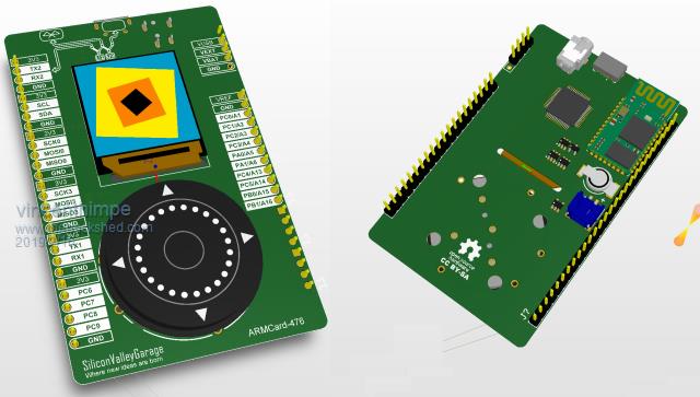 |
||||
| lizby Guru Joined: 17/05/2016 Location: United StatesPosts: 3782 |
Ah, I thought you were looking at doing a Nucleo-L4 64-pin backpack. Keep us posted. PicoMite, Armmite F4, SensorKits, MMBasic Hardware, Games, etc. on FOTS |
||||
goc30 Guru Joined: 12/04/2017 Location: FrancePosts: 435 |
Hi all I receive my Nucleo L476RG (l4 64 pins) I have also an LCD 1.3" 240x240 St7789 (lcd alone, not hat) Nucleo work correctly (benchmark ok, calc Pi ok) but in graphic mode, I have nothing on screen, always black (prog "Gauge") config: SPI2 CLK (p55 CN10-31) SPI2 MOSI (p57 CN10-29 SPI2 MISO (p56 CN10-27) (not use) GND CN7-19 +3.3v CN7-16 DC P51 (CN7-1) CS P52 (CN7-2) RST p53 (CN7-3) BLK not use CPU 80 OPTION LCDPANEL ST7789, LANDSCAPE, 51, 53, 52 ARMmite L4 MMBasic Version 5.05.09 prog test: Gauge lcd work correctly on arduino uno (graphic test) I have change speed (CPU 48), nothing! I have also tested without CS signal (this signal is not wired on "chinese" LCD, I have add this, and after, it is good on UNO I have tested with ver 5.05.07. Its same pb help.. help ...help |
||||
| lizby Guru Joined: 17/05/2016 Location: United StatesPosts: 3782 |
It's a different animal, but for the ILI9341, I had to have "LED" (BL) powered to have anything appear on the screen. I was able to get by with 3.3V through a 68 ohm resistor. (But I can't say whether or not that would be safe or effective on your St7789.) PicoMite, Armmite F4, SensorKits, MMBasic Hardware, Games, etc. on FOTS |
||||
disco4now Guru Joined: 18/12/2014 Location: AustraliaPosts: 1127 |
Hi, I have one of these ST7789 clones that comes without the CS pin exposed. I have the source for Peter's driver for the MM2 and MM+ but have not been able to get it to go as is , i.e. with CS permanently selected on the board. Apparently when they work with Arduino, they use SPI mode 3 but I have no success. In the end I modified it to expose the CS pin in lieu of the BLK pin. After the modification it works on the Nucleo L476RG (l4 64 pins) with MMBasic set up as you have it.i.e. OPTION LCDPANEL ST7789, LANDSCAPE, 51, 53, 52 ARMmite L4 MMBasic Version 5.05.09 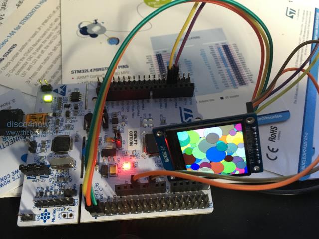 Here is my modification: 1. Remove R2 2. Pin 8 of the ribbon is CS, it is connected to GND on the PCB but under the ribbon. I used a heat gun and lifted the ribbon, then cut the track at the base of pin 8 on the PCB, checking it was no longer connected to ground. 3. Put the ribbon back 4. Run a small wire from pin 8 to the R2 pad that goes to the BLK pin. 5. BLK is now gone and is now CS. The bit you may not have done is remove the permanent GND on CS, this seems to stop it working, the GND being applied by CS is what triggers the initialisation. . 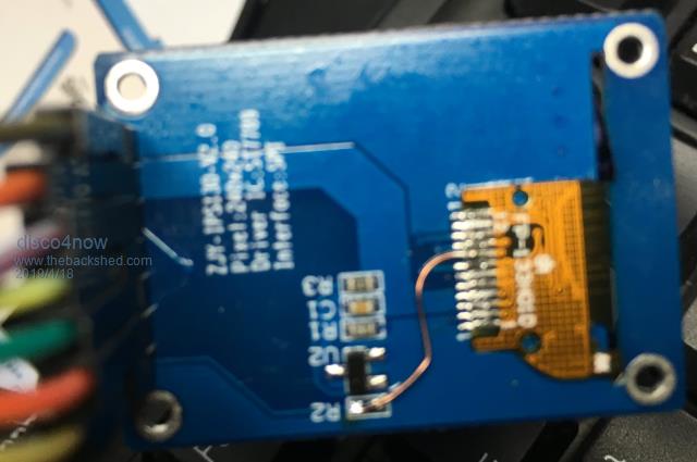 Gerry F4 H7FotSF4xGT |
||||
| CaptainBoing Guru Joined: 07/09/2016 Location: United KingdomPosts: 2171 |
excellent work |
||||
| goc30 Guru Joined: 12/04/2017 Location: FrancePosts: 435 |
Hi Disco Thank for infos I have make other change. I have add CS signal, by solder pin8 of ribbon on new pin, I have a 8 pins connector and not 7 pins In this case , it work perfectly with Arduino Uno (adafruit graphtest) Other reason to use Cs signal, is that I want to use 2 LCD for making 2 eyes's simul |
||||
| goc30 Guru Joined: 12/04/2017 Location: FrancePosts: 435 |
You are absolutely right, it is this GND that prevents the smooth operation. But I cannot understand why on the UNO it works anyway, and not on the NANO may be GBD signal on LCD is not good I have no heat gun, I search another way to cut GND on CS or I will desolder the pin on ribbon directly and put the small wire on ribbon (pin8) thank for your help |
||||
| Page 1 of 2 |
|||||
| The Back Shed's forum code is written, and hosted, in Australia. | © JAQ Software 2026 |
