
|
|
Forum Index : Microcontroller and PC projects : RTC on Nucleo-L432
| Author | Message | ||||
| lizby Guru Joined: 17/05/2016 Location: United StatesPosts: 3784 |
Unless I've missed something, there appears to be no convenient way to maintain the built-in RTC on the Nucleo-L432 (if there is one)--there is no VBat pin brought out. I've programmed the date into a DS3231 RTC and hooked it up on I2C, but it appears to start reading at byte 2 instead of byte 0: > dim integer iRTC(8) > i2c open 100, 1000 > I2C read 104,0,7,iRTC() > for i=0 to 6: print hex$(iRTC(i),2);: next i 19062303191000 > It should have printed 21171906230319 for 23-03-19 19:17:21. What am I doing wrong? How do you set the initial read location for an I2C read? Also, after I2C CLOSE, (in an attempt to re-open with the location pointer set to 0), I get an error with a new I2C OPEN: > i2c close > i2c open 100, 1000 Error: I2C already OPEN PicoMite, Armmite F4, SensorKits, MMBasic Hardware, Games, etc. on FOTS |
||||
| erbp Senior Member Joined: 03/05/2016 Location: AustraliaPosts: 195 |
Hi, Following is a snippet of code I am using on an E28 to get the date / time from a DS3231 RTC module. I guess this should also work on a Nucleo-L432. I2C Open 100, 200 'Open the I2C communication session Pause 100 on Error Skip 1 RTC GetTime 'Set MM Date & Time from RTC module via I2C If MM.ERRNO <> 0 then 'RTC not present (or failed to communicate) Print "RTC GetTime Error: " + Str$(MM.ERRNO) + " - " + MM.ErrMsg$ Else Print "MM Date/Time set from RTC: " + Date$ + " " + Time$ Endif I2C Close 'close I2C communication session (releases pins 17 & 18) Cheers, Phil |
||||
| lizby Guru Joined: 17/05/2016 Location: United StatesPosts: 3784 |
Phil--the RTC command is omitted on the Armmite distributions--because of the internal RTC. PicoMite, Armmite F4, SensorKits, MMBasic Hardware, Games, etc. on FOTS |
||||
| erbp Senior Member Joined: 03/05/2016 Location: AustraliaPosts: 195 |
Hi Lizby, Oh, sorry I didn't know that - I haven't really followed all the Armmite developments. In that case my code snippet won't help at all. |
||||
palcal Guru Joined: 12/10/2011 Location: AustraliaPosts: 2039 |
I asked the same question re the RTC some time ago, TassyJim's reply was to put the chip to sleep and leave it powered. "It is better to be ignorant and ask a stupid question than to be plain Stupid and not ask at all" |
||||
| matherp Guru Joined: 11/12/2012 Location: United KingdomPosts: 11512 |
Write the start address to the chip before the read. In this case I2C WRITE 104, 0, 1, 0 This is fairly standard I2C protocol for most chips where you need to set the read address. Also remember the chip returns BCD data not ASCII Thanks: I'll look at that For some reason on this chip there isn't a VBAT even though pin 1 is VDD which is the pin normally used for VBAT on all the other L4 versions. I suspect there is a silicon error in this chip. As palcal says : "I asked the same question re the RTC some time ago, TassyJim's reply was to put the chip to sleep and leave it powered." Here is fully worked code for setting the DS3231 from the RTC and setting the RTC from the DS3231 Option explicit option default NONE const ds3231 = 104 I2C open 400,1000 DS3231set DS3231read print time$," ",day$(now)," ",date$ end sub DS3231set 'sets the DS3231 from the RTC local integer s,m,h,day,d,mn,y local t$=time$, dt$=date$, dy$=day$(now) s=(ASC(MID$(t$,8,1))-48) or ((ASC(mid$(t$,7,1))-48)<<4) m=(ASC(MID$(t$,5,1))-48) or ((ASC(mid$(t$,4,1))-48)<<4) h=(ASC(MID$(t$,2,1))-48) or ((ASC(mid$(t$,1,1))-48)<<4) d=(ASC(MID$(dt$,2,1))-48) or ((ASC(mid$(dt$,1,1))-48)<<4) mn=(ASC(MID$(dt$,5,1))-48) or ((ASC(mid$(dt$,4,1))-48)<<4) y=(ASC(MID$(dt$,10,1))-48) or ((ASC(mid$(dt$,9,1))-48)<<4) if left$(dy$,2)="Su" then day=1 if left$(dy$,1)="M" then day=2 if left$(dy$,2)="Tu" then day=3 if left$(dy$,1)="W" then day=4 if left$(dy$,2)="Th" then day=5 if left$(dy$,1)="F" then day=6 if left$(dy$,2)="Sa" then day=7 i2c write ds3231,0,8,0,s,m,h,day,d,mn,y end sub sub DS3231read 'sets the RTC from the DS3231 local integer r(6) local integer s,m,h,day,d,mn,y local t$, dt$ i2c write ds3231,0,1,0 i2c read ds3231,0,7,r() s=(r(0) and 15) + ((r(0) >>4) * 10) m=(r(1) and 15) + ((r(1) >>4) * 10) h=(r(2) and 15) + ((r(2) >>4) * 10) day=(r(3) and 15) d=(r(4) and 15) + ((r(4) >>4) * 10) mn=(r(5) and 15) + ((r(5) >>4) * 10) y=(r(6) and 15) + ((r(6) >>4) * 10) t$=RIGHt$(str$(h+100),2)+":"+RIGHt$(str$(m+100),2)+":"+RIGHt$(str$(s+100),2) dt$=RIGHt$(str$(d+100),2)+"-"+RIGHt$(str$(mn+100),2)+"-"+str$(y+2000) time$=t$ date$=dt$ end sub |
||||
| lizby Guru Joined: 17/05/2016 Location: United StatesPosts: 3784 |
Thanks--that did the trick. I thought it would have the disadvantage of setting the seconds to 0 each time it was run (upon power cycling), but it appears it does not. (Why not?) Having for the first time found the HEX$ function when I was originally looking to display the BCD output, I realized it would provide an easy way to set the date and time: [code] dim integer iRTC(8) i2c open 100, 1000 I2C write 104,0,1,0 I2C read 104,0,7,iRTC() for i=0 to 6: print hex$(iRTC(i),2);: next i date$=hex$(iRTC(4),2)+"-"+hex$(iRTC(5),2)+"-"+hex$(iRTC(6),2) time$=hex$(iRTC(2),2)+":"+hex$(iRTC(1),2)+":"+hex$(iRTC(0),2) print date$+" "+time$ [/code] The output is: 24-03-2019 09:48:13 Thanks for the suggestion. I thought of that, but am enjoying the convenience of plugging in just this little L432-on-a-breadboard into my laptop. (Note: "I2C CLOSE" is fixed, thanks.) PicoMite, Armmite F4, SensorKits, MMBasic Hardware, Games, etc. on FOTS |
||||
| lizby Guru Joined: 17/05/2016 Location: United StatesPosts: 3784 |
While we're at it with I2C, here is an MCP23017 16-pin I/O expander: 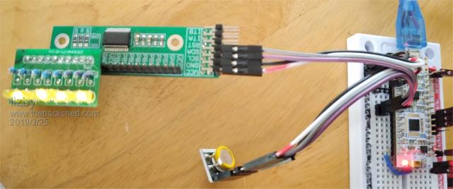 [code] ' L4_mcp23017 option base 1 option explicit dim as integer i,j,k,l,m,n dim as string A,B,C,D const mcp23017 = &h20 ' A2, A1, A0, R/W all connected to 0V const IODIRA = &h00 ' Port A IO Direction register DEFAULT = I/P const IODIRB = &h01 ' Port B IO Direction register DEFAULT = I/P const IOCON = &h0A ' IO Expander config register - address &h0B accesses the same register const GPIOA = &h12 ' Port A General purpose register const GPIOB = &h13 ' Port B General Purpose register const OLATA = &h14 ' Port A latch register const OLATB = &h15 ' Port B latch register RTC_GetTime print date$+" "+time$ I2C open 100, 1000 I2C WRITE MCP23017,0,2,IODIRA,0 ' set direction to output I2C WRITE MCP23017,0,2,IODIRB,0 ' set direction to output do gosub mcp17 loop mcp17: I2C WRITE MCP23017,0,2,IODIRA,0 ' set direction to output I2C WRITE MCP23017,0,2,IODIRB,0 ' set direction to output print "write to mcp23017: "+date$+" "+time$ for i = 1 to 6 I2C Write MCP23017,0,2,OLATA,&b10101010 ' I2C Write MCP23017,0,2,OLATB,&b01010101 ' PAUSE 500 I2C Write MCP23017,0,2,OLATA,&b01010101 ' I2C Write MCP23017,0,2,OLATB,&b10101010 ' PAUSE 500 Next i I2C Write MCP23017,0,2,OLATA,0 ' turn all off I2C Write MCP23017,0,2,OLATB,0 ' turn all off return SUB RTC_GetTime local integer iRTC(8) I2C open 100, 1000 I2C write 104,0,1,0 I2C read 104,0,7,iRTC() ' for i=1 to 7: print hex$(iRTC(i),2);: next i date$=hex$(iRTC(5),2)+"-"+hex$(iRTC(6),2)+"-"+hex$(iRTC(7),2) ' print hex$(iRTC(5),2)+"-"+hex$(iRTC(6),2)+"-"+hex$(iRTC(7),2) time$=hex$(iRTC(3),2)+":"+hex$(iRTC(2),2)+":"+hex$(iRTC(1),2) ' print hex$(iRTC(3),2)+":"+hex$(iRTC(2),2)+":"+hex$(iRTC(1),2) I2C close return ' RTC_GetTime [/code] PicoMite, Armmite F4, SensorKits, MMBasic Hardware, Games, etc. on FOTS |
||||
| lizby Guru Joined: 17/05/2016 Location: United StatesPosts: 3784 |
There appears to be a conflict between I2C and OPTION LCDPANEL ILI9341, LANDSCAPE, 11, 10, 9 When I added the OPTION LCDPANEL ILI9341, "I2C write 104,0,1,0" returns an error in "print mm.i2c". If I disable with "OPTION LCDPANEL DISABLE", the I2C WRITE doesn't return an error. Enable the ILI9341 again and the error reappears; disable it and it goes away. [code] ARMmite L4 MMBasic Version 5.05.09 Copyright 2011-2019 Geoff Graham Copyright 2016-2019 Peter Mather > option list OPTION LCDPANEL ILI9341, LANDSCAPE, 11, 10, 9 > OPTION LCDPANEL disable > option list > dim integer i,iRTC(8) > I2C open 100, 1000 > print mm.i2c 0 > I2C write 104,0,1,0 > print mm.i2c 0 > print mm.i2c 0 > I2C read 104,0,7,iRTC() > for i=0 to 6: print hex$(iRTC(i),2);: next i 06331107240319 > OPTION LCDPANEL ILI9341, LANDSCAPE, 11, 10, 9 > option list OPTION LCDPANEL ILI9341, LANDSCAPE, 11, 10, 9 > I2C write 104,0,1,0 Error: I2C not open > I2C open 100, 1000 > print mm.i2c 0 > I2C write 104,0,1,0 > print mm.i2c 1 > > > OPTION LCDPANEL disable > I2C close > print mm.i2c 0 > I2C open 100, 1000 > print mm.i2c 0 > I2C write 104,0,1,0 > print mm.i2c 0 [/code] PicoMite, Armmite F4, SensorKits, MMBasic Hardware, Games, etc. on FOTS |
||||
| matherp Guru Joined: 11/12/2012 Location: United KingdomPosts: 11512 |
Do you get the error if the ILI9341 isn't physically connected but is enabled? If not then it will be a power issue. I haven't got a Nucleo-L432 at the moment but it works fine on my 48-pin backpack and on a breadboarded 32-pin L432KG. |
||||
| lizby Guru Joined: 17/05/2016 Location: United StatesPosts: 3784 |
I still get the error if the ILI9341 is completely disconnected. I'm powering this through one of the little USB voltage and current LCDs. It never exceeds .01A (I wish it showed more decimal places). It also occurs with "Option LCDPanel N5110,L,11,10,9,&HC0" with no Nokia LCD connected. OPTION LCDPANEL DISABLE makes I2C work again. PicoMite, Armmite F4, SensorKits, MMBasic Hardware, Games, etc. on FOTS |
||||
| lizby Guru Joined: 17/05/2016 Location: United StatesPosts: 3784 |
Not specifically RTC related, but I2C, so I'll post here. I'm about half-blinded staring at the Nucleo-L746 board, the Armmite L4 manual, and the STM Nucleo-64 pdf: Nucleo-64 But I can't get I2C to work. I'm connecting the DS3231 RTC (yes, I know there's an onboard RTC which works if I provide VBAT, but I haven't gotten that far yet). The DS3231 had the date programmed by a picaxe, and it shows the date properly when read by the picaxe (or by the Nucleo L432). On the L746RG board I'm connecting I2C-SDA to D14 and I2C-SLA to D8 (pins 59 and 58--B7 & B6). I2C OPEN works, but I2C write 104,0,1,0 give an error in mm.i2c. I've run twofingers' scanner, and it doesn't find the RTC: [code] '********************************** ' I2C-Scanner ' scans I2C-Bus for I2C addresses ' MM-Basic 4.5 / Maximite/Duinomite ' by twofingers 21-08-2014 on TBS '********************************** I2CScanner end Sub I2CScanner Local found, i found=0 ' Cls Print "I2C-Scanner from Adr. 8-119":Print:Print I2C open 100, 1000 ' i2c enable 100kHz, 1000ms timeout For i = &h08 To &h77 ' gueltige I2C-Adressen von 8-119 I2C read i, 0, 1, temp Print i;">"; MM.I2C " "; If MM.I2C = 0 Then Print:Print:Print "Found I2C-Address at "; i; " ("dec2hex$(i)+")" found=1 EndIf Next i I2C close ' i2c disable If found = 0 Then Print:Print:Print "NO I2C-Address found!" End Sub Function dec2hex$(number) ' uused by I2C-Scanner dec2hex$ = "&H"+ Hex$(number) End Function '*********************************************************** [/code] Here is my understanding of the pinout by connector (CN5 & CN6). 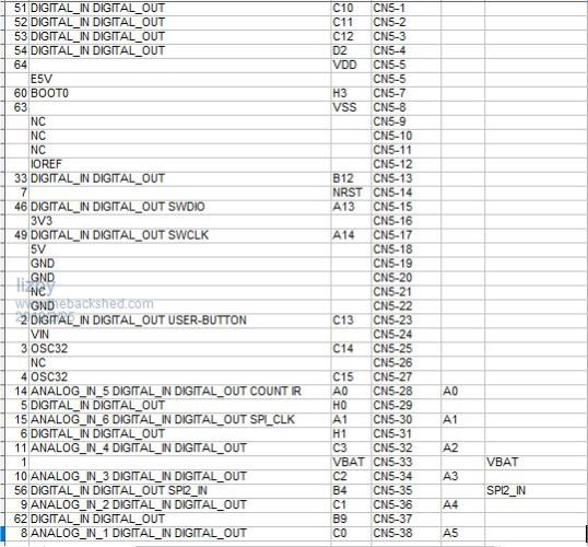 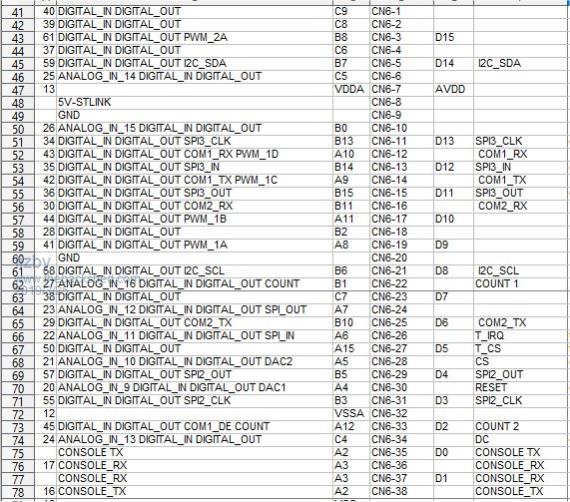 If someone can tell me that I2C works for them with the Nucleo-L476, and what the connections are, I'll stare at it some more. PicoMite, Armmite F4, SensorKits, MMBasic Hardware, Games, etc. on FOTS |
||||
TassyJim Guru Joined: 07/08/2011 Location: AustraliaPosts: 6538 |
I don't have the L476 (I assume that's the one you have and L746 was a typo) On my L433 Nucleo-64 I connected the RTC as per Peter's manual, which I think is the same as you.  > RUN I2C-Scanner from Adr. 8-119 8> 1 9> 1 10> 1 11> 1 12> 1 13> 1 14> 1 15> 1 Found I2C-Address at 104 (&H68) 105> 1 106> 1 107> 1 108> 1 109> 1 110> 1 111> 1 > Try testing your pins with SETPIN DOUT to make sure that they do work. Apart from that, I don't have any suggestions. Jim VK7JH MMedit |
||||
| matherp Guru Joined: 11/12/2012 Location: United KingdomPosts: 11512 |
Best way to get the pins is to correlate the port number in the pinout listing in the manual with the Nucleo datasheet. The manual gives: 58 DIGITAL_IN DIGITAL_OUT I2C_SCL B6 59 DIGITAL_IN DIGITAL_OUT I2C_SDA B7 looking at the Nucleo datasheet 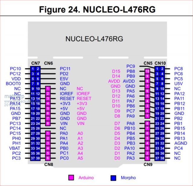 gives CN10-17 or Arduin-D10 for B6 and CN7-21 for B7. This appears to works properly talking to a DS3231. 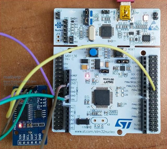 |
||||
| lizby Guru Joined: 17/05/2016 Location: United StatesPosts: 3784 |
Thank you very much for that, and for the L476RG pinout image--I had somehow managed to get the wrong one, so no amount of staring would have helped me. ... And that works--thank you again. Now back to the drawing board for the rest of the connections. (I had gotten my pin-number to pin-name connection from the STM32 Nucleo-64-P boards pdf, which doesn't include the L476RG pinouts (which are different). The correct chart is in this PDF: Nucleo-64 ) 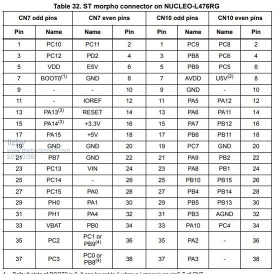 PicoMite, Armmite F4, SensorKits, MMBasic Hardware, Games, etc. on FOTS |
||||
| lizby Guru Joined: 17/05/2016 Location: United StatesPosts: 3784 |
EOF appears not to be detected with LINE INPUT: > new > dim i as integer, A as string > open "T" for output as #1 > for i=1 to 6: print #1,i: next i: close #1 > open "T" for input as #1 > do while not eof(1): line input #1,A: print A: loop 1 2 3 4 5 6 7 8 9 Error: Line is too long > Also note that 9 lines are printed instead of 6. I had previously written 9--apparently 'open "T" for output' doesn't renew the file (and/or CLOSE #1 doesn't do whatever is needed to mark EOF). PicoMite, Armmite F4, SensorKits, MMBasic Hardware, Games, etc. on FOTS |
||||
| matherp Guru Joined: 11/12/2012 Location: United KingdomPosts: 11512 |
Thanks for the report. This found two errors + a feature in all versions of MMBasic The attached should fix the bugs and the "feature" 2019-03-27_212036_ArmmiteL4.zip The feature was that the program below would output a blank line after the 6th line before EOF was seen. This was because LINE INPUT terminated on CR and there was still a LF in the file. Normally this would be discarded by LINE INPUT as it reads the next line, but at the end of the file it triggers an extra loop of the program before EOF is seen. The workround on other Micromite variants would be to test for an empty string before doing the print of A Dim i As integer, a As string Open "T" For output As #1 For i=1 To 6: Print #1,i: Next i: Close #1 Open "T" For input As #1 Do While Not Eof(1) Print Eof(1) Line Input #1,a Print a 'test for empty string to avoid extra print Loop |
||||
| lizby Guru Joined: 17/05/2016 Location: United StatesPosts: 3784 |
Obscure error resulting from updating to this version, but may well not be version-related. After copying in the .bin file, I pressed reset and entered these: OPTION LCDPANEL ILI9341, RLANDSCAPE, 24, 35, 34 OPTION TOUCH 28, 36 OPTION FLASH 41 After reset, I got "EF4017 found 2048 blocks", did 'LOAD "g7.bas"', then RUN, and after some output, got "Error: Display not configured" Then the following: [code] > option list OPTION BAUDRATE 230400 OPTION TOUCH 28, 36 OPTION FLASH 41 > OPTION LCDPANEL ILI9341, RLANDSCAPE, 24, 35, 34 EF4017 found 2048 blocks Error: Corrupted EF4017 found 2048 blocks Error: Corrupted EF4017 found 2048 blocks Error: Corrupted ARMmite L4 MMBasic Version 5.05.09 Copyright 2011-2019 Geoff Graham Copyright 2016-2019 Peter Mather EF4017 found 2048 blocksARMmite L4 MMBasic Version 5.05.09 Copyright 2011-2019 Geoff Graham Copyright 2016-2019 Peter Mather EF4017 found 2048 blocksARMmite L4 MMBasic Version 5.05.09 Copyright 2011-2019 Geoff Graham Copyright 2016-2019 Peter Mather EF4017 found 2048 blocks [/code] After the 3rd "Error: Corrupted" I unplugged and plugged back in. Now I don't get a prompt after "EF4017 found 2048 blocks". I copied in the previous bin file from 2019-03-24_201532_ArmmiteL4.zip and still on startup after "OPTION FLASH 41" get "EF4017 found 2048 blocks" and no prompt. I'm going to reflash the new .bin file and try the "FORMAT 41" process. PicoMite, Armmite F4, SensorKits, MMBasic Hardware, Games, etc. on FOTS |
||||
| The Back Shed's forum code is written, and hosted, in Australia. | © JAQ Software 2026 |
