
|
|
Forum Index : Electronics : Inverter synchronising
| Page 1 of 3 |
|||||
| Author | Message | ||||
| Tinker Guru Joined: 07/11/2007 Location: AustraliaPosts: 1904 |
To connect the AC of my two test inverters together in sync I made this box: 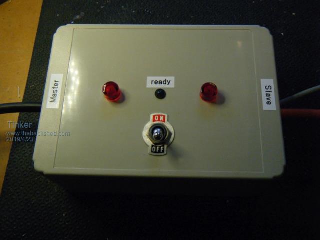 It looks plain enough on the outside but not inside  : :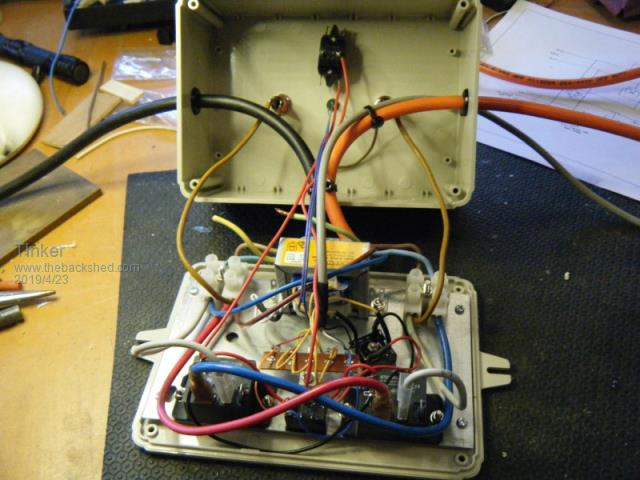 It was surprising that the connections of the simple schematic created such a rats nest of wiring. Just as well I choose a large jiffy box as it got pretty full in the end. 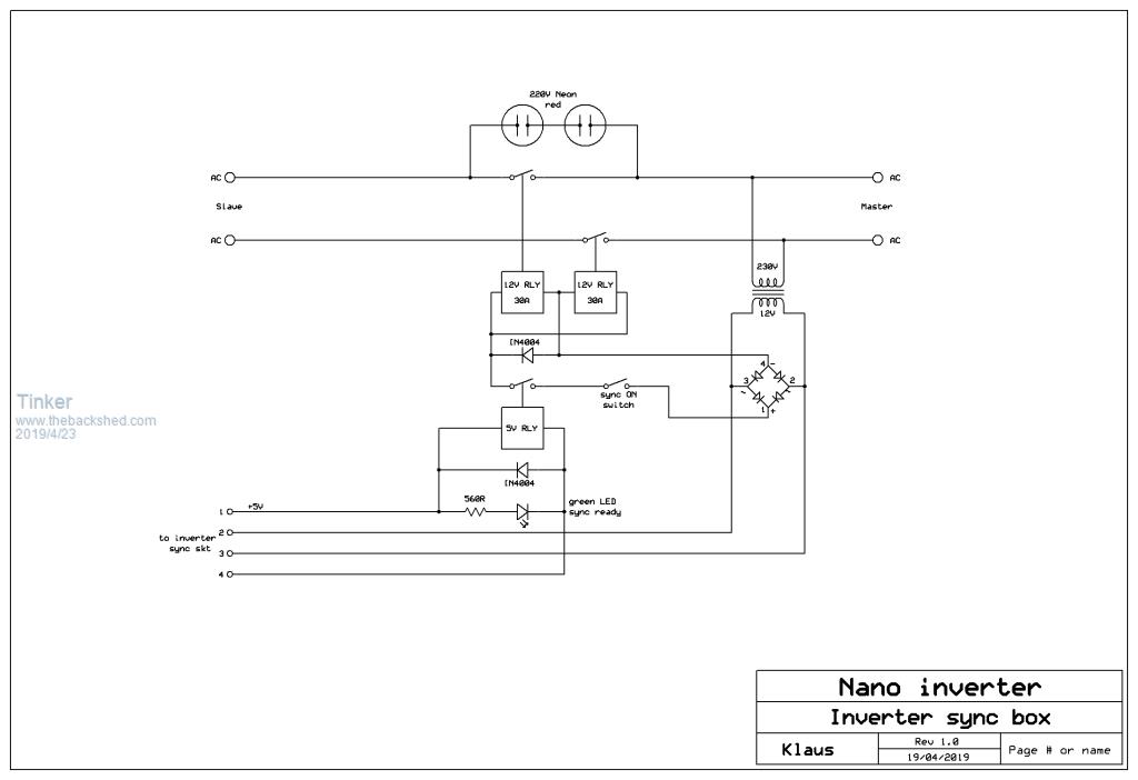 Some explanations: The two Neons in series indicate when the two inputs are in sync or not. They go bright when 180 degrees out and extinguish when in phase. Its just an indicator if a two trace CRO was not handy. BTW, that CRO must have its ground isolated. I use 100:1 home made probe adapters which can plug directly into a AC GPO. The switch is the final manual control to synchronise, I did not want that to happen automatically - and just as well .The green 'ready' LED shows when the nano inverter (Slave) has synchronised to the master inverter. This is the test set up: 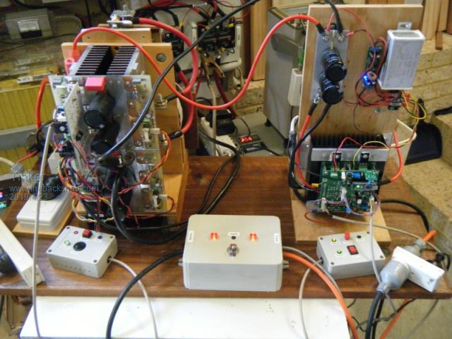 Setting up: Switch OFF, Adjust both inverters to the same voltage (230V), no load connected, both inverter outputs monitored by oscilloscope trace, Synch inhibit link in place on nano inverter control board. The Master is a EG8010 based inverter, the Slave a nano inverter. OK, powering inverters up, the Neons light & go dark and the CRO traces show how the two sine waves drift in and out of sync. Good so far, now removing the sync inhibit link (I use a two pin shunt header). The green ready LED comes on and the CRO traces immediately try to align but come to rest 180 degrees out of phase. That is where fitting that switch had paid off  Problem was easily fixed by swapping the primary leads of that little transformer inside the box. Try again, the CRO traces now in sync but not quite  , see pic: , see pic: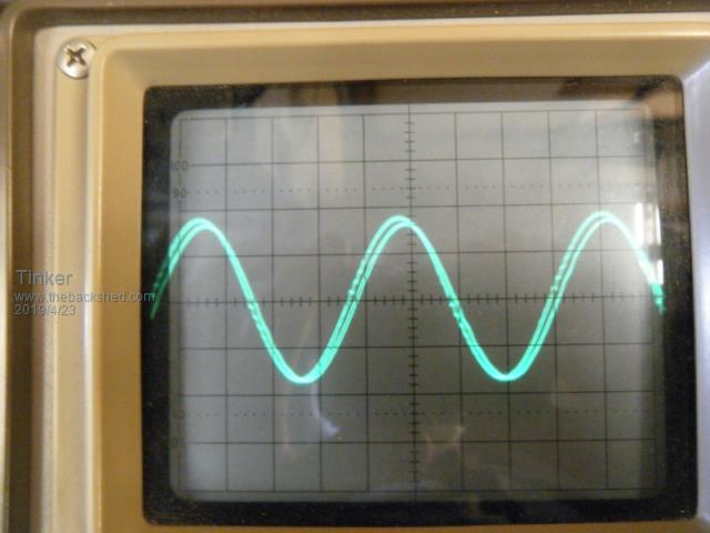 The 'serrated' trace is from the EG8010 inverter. No idea why, so, after scratching my head for a while, I decided to throw the switch ON. Well, no bang but the 5V relay was cattering badly and the sine wave developed a hump on its side. No good. So, poida's nano program enables the inverters to synchronise but not quite complete, the wave peaks are a few degrees out from each other and locked in that state. I am open to ideas as how to fix that. Meanwhile I will complete another nano control board and fit it to inverter #4 to replace that EG8010 board. That inverter will have the sync inhibit link in place so it remains the Master. Klaus |
||||
| poida Guru Joined: 02/02/2017 Location: AustraliaPosts: 1480 |
ISR (INT0_vect) { if (int_f == 0) { return; // only once per 50 Hz cycle. Noise! much noise... } int_f = 0; pcint = pcount + (v1low == 1?200:0) - 200; // get position in 50Hz waveform, -200 to 200 counts // pcint is position in output waveform when this interrupt occurs phase_error = (pcint - 4); // subtract setpoint, 0 for my setup, in counts the "location" where the slave locks onto the master is defined in the below line: phase_error = (pcint-4) pcint = the phase angle of the slave when the mains sync interrupt occurs. The angle is measured in counts, where 200 counts = 1/2 of 50Hz. Each count = 1/20kHz Now, I subtract 4 since that lines up my test mains sync master signal quite well with the slave. The 4 accounts for delays that exist in the mains sync signal sample processing, including the opto coupler delay and interrupt latency. We can have any value, it does not need to be 4. I expected we will need to alter this value, to suit local conditions. Each of our builds probably will need a different value than 4 to align the two waveforms. So, could I suggest you try a different value than 4 in that line, maybe 0. This value can be anything, positive or negative. Try 0 and load that code into nano1 and see how things line up. Or not. 0 - 200 counts is equivalent to 0 to 180 degrees phase difference. Have a go and show us what value lines up things with your system. wronger than a phone book full of wrong phone numbers |
||||
| Tinker Guru Joined: 07/11/2007 Location: AustraliaPosts: 1904 |
Thanks, I'll try that. Maybe I can surprise myself by being able to modify your program to work better . Klaus |
||||
| johnmc Senior Member Joined: 21/01/2011 Location: AustraliaPosts: 283 |
Klaus , Thanks for your post, on your journey into land of synchronising , much appreciated cheers john johnmc |
||||
| Tinker Guru Joined: 07/11/2007 Location: AustraliaPosts: 1904 |
All in the spirit of this forum John. And a lot of fun in the bargain .Klaus |
||||
| poida Guru Joined: 02/02/2017 Location: AustraliaPosts: 1480 |
It's funny to my mind that I always envisaged that the tuning of the sync master would be done in software. You are a more hardware guy, Tinker. You could go analog and alter the timing of the trigger signal with respect to phase angle of the master AC waveform. If possible, add a potentiometer to control amplitude, in series with 12V AC pin 2 or 3 of your schematic. If adding a little resistance moves the AC waveforms closer, great! If they diverge, maybe change the 680R to something smaller. wronger than a phone book full of wrong phone numbers |
||||
| Tinker Guru Joined: 07/11/2007 Location: AustraliaPosts: 1904 |
Thanks poida, you are giving me more ideas to try. Today I played your numbers game in that sine wave program. I found by replacing the "4" with -6 the sine waves were matched in phase. I could not see any offset on my old CRO. So the panic switch was turned on and all seemed well for a few seconds. Then my master inverter (EG8010 driven) started to growl and getting louder until the relay dropped out and disconnected. The sine wave started to distort badly as the growl increased. I assume that relay dropping out is a safety feature you incorporated in case the sync was compromised? If so - good idea , no resulting 'bang'.Anyway, perhaps that nano program does not like the EG8010 sine wave. To test that I am now getting another nano control board ready, to run my master inverter instead of the EG8010 board. To connect that board to the totem pole drivers in there I have to get the drive connectors sorted to suit. I'm so glad I decided long ago to use individual connectors and not a ribbon cable for this, so much easier to change connections. Klaus |
||||
| Solar Mike Guru Joined: 08/02/2015 Location: New ZealandPosts: 1224 |
Once synchronized, perhaps the inverter with the highest mains output voltage is now attempting to push power back through the transformer of the other, this may cause the voltage waveform to change and have some unusual side effects. It is unlikely both output AC voltages will be exactly the same. Mike |
||||
| hary Regular Member Joined: 15/04/2019 Location: FrancePosts: 89 |
Hi there. As I'm far from being a specialist, I don't want to disturb this post, but are you aware that when paralleling Diesel generator, you must of course synchronize them, but also, you must adjust reactive power and load between each other ? otherwise, you might "inject" power from one to another and vice versa ! I could foresee something I would call a "regulation pumping effect". I don't know if it make any sense ? That might be what Tinker has faced. |
||||
| Tinker Guru Joined: 07/11/2007 Location: AustraliaPosts: 1904 |
No hary, what you write does not make sense. You should try to read my post again and then realise I was paralleling two *inverters*. Nothing to do with rotating machinery at all. Klaus |
||||
| hary Regular Member Joined: 15/04/2019 Location: FrancePosts: 89 |
I'm absolutely aware of that you're trying paralleling 2 inverters. But I thought, kind of the same things could happen on inverter too as I think both inverter have their own regulation. Plus from what I read, I haven't seen each inverter's regulation are connected together (or are talking to each other). On Diesel generator, again, The both regulation has to be monitored and control from a main one, like a master. From what I've seen about paralleling inverter, they need a specific control board added and a specific communication link together ! Like here But again, I apologize if I'm the wrong way ! |
||||
| Mulver Senior Member Joined: 27/02/2017 Location: AustraliaPosts: 160 |
I have a small 2kva inverter type generator that has the option to link 2 together by just the Active and Neutral. So i think synchronisation is possible but i do think some kind of regulation control is required beyond the standard inverter. Possible delayed response time for one inverter to load changes to avoid them both hunting to chase the same load at the same time??? (the pumping effect Harry has mentioned) Have you tested synchronisation while running a resistive load? |
||||
| Tinker Guru Joined: 07/11/2007 Location: AustraliaPosts: 1904 |
At this stage just maintaining sync is not yet done - a quite elusive task .I do not *need* to sync two inverters. Its just that the possibility for it needs to be tested on two separate inverters to confirm poida's claim the nano inverter can sync to 50Hz (sampled of mains frequency). Else, why have this function available? Klaus |
||||
| Mulver Senior Member Joined: 27/02/2017 Location: AustraliaPosts: 160 |
Your willingness to put your own creations on the line for testing purposes is awesome! Regarding other functions. Swapping loads at zero crossing between two inverters or on and off grid ?? Ability to create multiple phase output if offsetting by a set amount? Ie 120deg for 3 inverters? |
||||
| poida Guru Joined: 02/02/2017 Location: AustraliaPosts: 1480 |
This thread here has been most educational for my understanding of mains sync. Harry said an important thing: the 2 inverters or generators, each running closed loop output control, might end up pushing and pulling each other in a possibly destructive manner. Maybe we need to have one of the 2 devices no longer in closed loop control. e.g. have slave just putting out maybe 230V AC, and have master outputting 240V with closed loop control. Once loads cause master to no longer be able to maintain 240V, and the voltage drops to around 230, then the slave starts to source current. While output is >230 V, the slave sinks current. What effect that may have is in the realm of dreams to me. I have never had any difficulty in having the nanoverter code sync to a signal, no matter how that signal was obtained. Anything that generates a 0 to 5V pulse (into pin2) at about 49 to 51 Hz always is synchronised wronger than a phone book full of wrong phone numbers |
||||
| Tinker Guru Joined: 07/11/2007 Location: AustraliaPosts: 1904 |
Yes poida, I know it worked for you but not so far for me .You hinted about opto drive signal before and, since I do use a different opto (it has not a darlington transistor stage inside), I might need more LED drive current and have changed that series resistor. But more testing is on hold until more HY4008's arrive since I managed to pop a few when trying to swap control boards on my test inverter #4. I'm aware of the power pushing /pulling issue but only experience (a long time ago) with rotary alternators being synchronised. That is different as the input power is mechanical (motor, turbine, etc.) What will happen when doing that with solid state inverters, sharing the same battery power source, does interest me, hence the experimenting. No amount of theories might hold up to practical observation IMO here .Lesson learned so far, both sources must have their frequencies in phase spot on to initiate sync, near enough is not an option. With no load on either inverter they 'should' stay synced, has not happened so far.... Klaus |
||||
| wiseguy Guru Joined: 21/06/2018 Location: AustraliaPosts: 1296 |
In Nov last year I posted this theory " its what happens after that point when we physically join the two together where I dont get something. We now have 2 AC sources tied together and cannot compare the phase relationship any more because they are always the same, however if the inverter or other source drifts by a small fraction it feels like there may be unintended energy transfer between the sources now that could become greater as the drift continues - no one else has commented on this so there must be something I am not getting and this is not actually going to happen." ? This post had a feeling of dejavu about it  I heartily agree with Poida about somehow making 1 nano master and sync the other nano to the first nano's output or similar scheme, Maybe we can track the two by synchronising the current waveforms ? If at first you dont succeed, I suggest you avoid sky diving.... Cheers Mike |
||||
| Solar Mike Guru Joined: 08/02/2015 Location: New ZealandPosts: 1224 |
Assuming both sources are now locked (both in Frequency and Phase), whichever source has a higher voltage than the other will push power back through the other inverter, to be synchronously rectified and charge its battery. This must affect the AC waveform somewhat, perhaps causing the voltage to rise and causing a pumping oscillation... Cheers Mike |
||||
| wiseguy Guru Joined: 21/06/2018 Location: AustraliaPosts: 1296 |
Before the relay or contactor closed and physically joined the two outputs together we had 2 sync waveforms to compare , adjust one then when they match close the relay. Now we have identical sync pulses always - even if one nano clock now drifts away slightly the two sync signals from the optos are (essentially) tied together so the nanos cant adjust for a discrepancy that doesnt exist ? My assumption was two matching inverters & matching voltages to simplify the understanding. If at first you dont succeed, I suggest you avoid sky diving.... Cheers Mike |
||||
Revlac Guru Joined: 31/12/2016 Location: AustraliaPosts: 1282 |
@Hary those parallel cards you linked to only work with those specific type and series of inverter that I am aware of, the other requirement with those is the part you can't see, inside (specific type and series of inverter) there is a parallel card with 2 pairs of back to back PHASE CONTROL SCR'S and a control circuit for it. I know this as I have one on the table here. Also likely to be some smarts on the main control card somewhere, Don't know how they do it (parallel) up to 9 units single or 3phase.? I think they are somehow locked? Anyway I think it works a bit different to the nano system here, I just thought it was worth mentioning. There are some large brushless generators that can be linked together, stamford has a MX341 REG "The AVR has the facility for droop CT connection, to allow parallel running with other similarly equipped generators." I know this it different to linking inverters, but maybe someone might read it and perhaps come up with a few suggestions/ideas. Just thinking... Cheers Aaron Off The Grid |
||||
| Page 1 of 3 |
|||||
| The Back Shed's forum code is written, and hosted, in Australia. | © JAQ Software 2026 |
