
|
|
Forum Index : Microcontroller and PC projects : Armmite F4: programming the firmware
| Page 1 of 16 |
|||||
| Author | Message | ||||
| matherp Guru Joined: 11/12/2012 Location: United KingdomPosts: 11599 |
I'm starting to put together the documentation for the Armmite F4 (STM32F407VET6) and the intention is to make it as complete as possible so I will post here the introductory documentation as I write it. This first post concerns programming the MMBasic firmware onto the board. I'm afraid I can't give any advice for Linux users. If anyone wants to replicate this documentation for Linux I will be pleased to include it in the documentation. Start by downloading the STM32CubeProgrammer software from ST.COM. If you have an account with ST use it to login and then the download will be active after you have accepted the terms and conditions. If not fill in the form with your name and email address. ST will send you an email with a download link. Click on the link and wait. A web page will be displayed but don't click on anything. After a short period the download will start automatically. With the STM32F407VET6 development board unplugged set the BT0 and BT1 jumpers as in the picture. 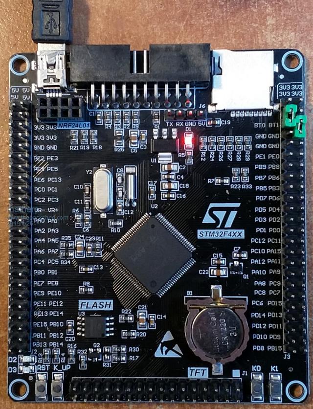 Plug in the USB connector and you should see the STM32Bootloader appear as a new device. 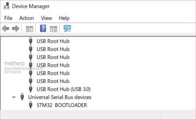 Run STM32CubeProgrammer and you should see the following screen 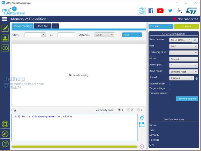 Click the STlink dropdown and select USB 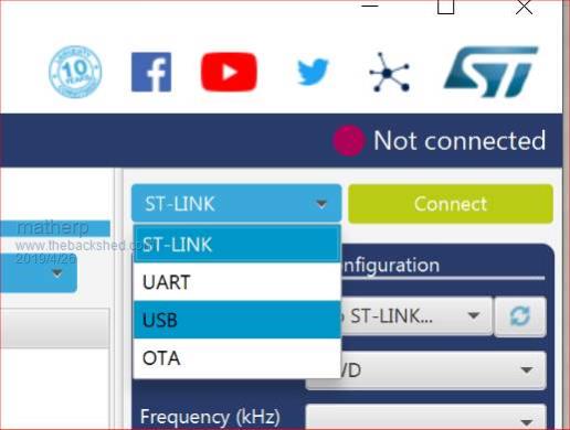 You should see the programmer find the STM32 Download USB device 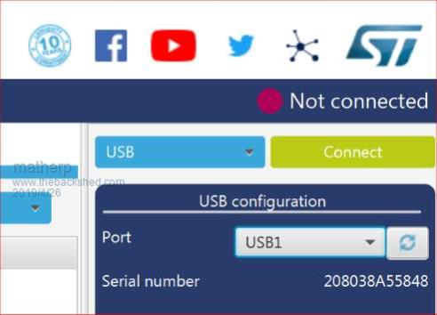 Click on "Connect" 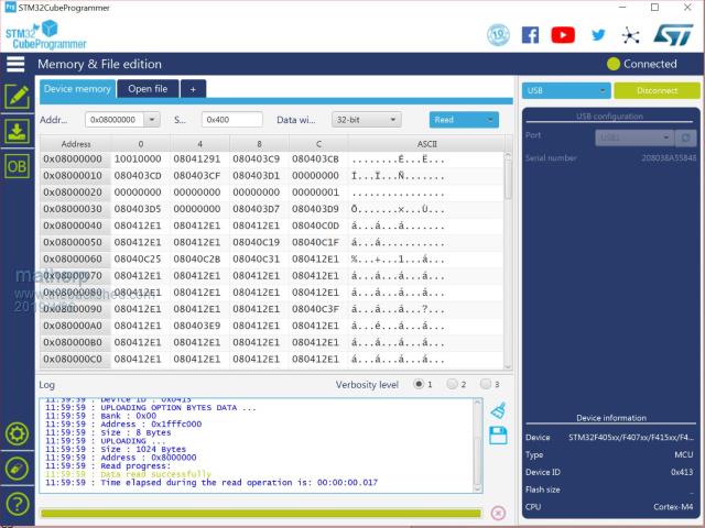 Then click on the download icon  and you will see this screen 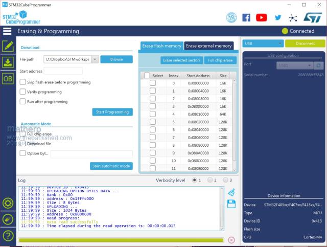 Click Browse, navigate to the file ArmmiteF4.hex and select it. Select "Verify programming" and then click "Start programming" 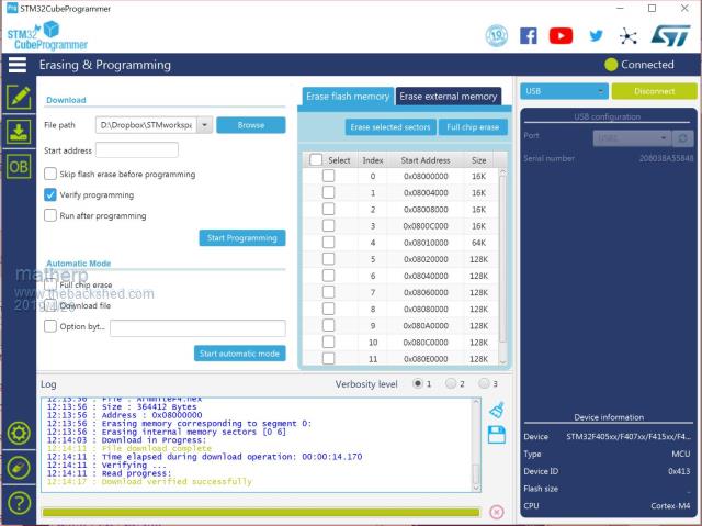 Congratulations the Armmite firmware is now programmed. You will only need to do this again for a new release. NB: you can also use this program to read existing firmware including option settings (and "saved" variables, if any) and save your own customised HEX file for use on other boards if required. Now close the STM32CubeProgrammer software and disconnect the USB port. Remove the BT1 link completely and move BT0 to connect to GND 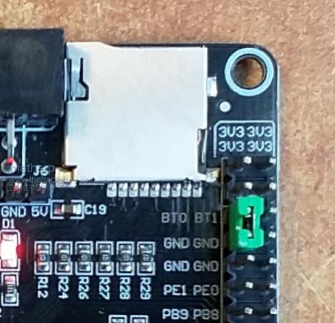 Plug the USB connector back in and the computer should see the ST USB virtual serial port. 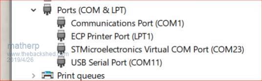 If this doesn't happen immediately try pressing the RST button on the board and unplugging and re-plugging the USB connection. Some computers seem to take time to recognise a different device on the same physical USB port. Connect a terminal emulator to the port and you should see the Armmite copyright banner 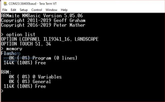 If not, press return to wake up the USB connection and it this still doesn't work try disconnecting the terminal emulator and re-connecting, pressing RST, unplugging and re-plugging. The Armmite firmware controls the CDC connection as follows: On power up, if no USB connection is plugged in (separate 5V supply) console output will be black-holed. On power up, if a USB connection is plugged in console output will be buffered until a terminal emulator is connected. Once running, if the USB connection is removed (separate 5V power) console output is black-holed Once running, if the USB connection is re-inserted, console output will be restored from the point at which the USB was re-connected. During development, USB resets can be a nuisance. You can use OPTION SERIAL CONSOLE ON to use an external USB/UART connected to the J6 header (just under and to the left of the SDcard slot in the picture above). The pinout on this is compatible with many of the CP2102 USB/UART PCBs which can be plugged directly onto the J6 header. In this mode the USB connection is completely disabled but you can still use the USB connection to power the board. Use: OPTION SERIAL CONSOLE OFF to re-enable USB. In this case the J6 header supports COM1 communications. The SDcard is always enabled in the Armmite F4 firmware and no configuration is necessary. By default the pin compatible ILI9341 TFT is also enabled together with the touch controller and this is pre-calibrated as in the screen-shot above. These can be disabled if required with: OPTION RESET You can use two new commands LIST COMMANDS LIST FUNCTIONS to display all the MMBasic functionality available on the ArmmiteF4 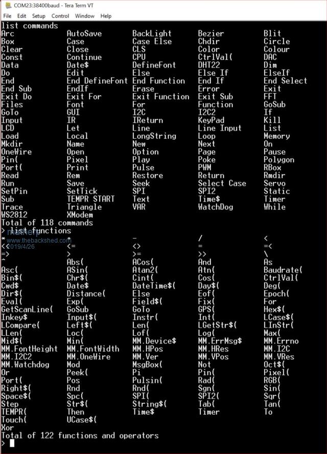 |
||||
goc30 Guru Joined: 12/04/2017 Location: FrancePosts: 435 |
What is best use Stlink or StmCube to load firmware? |
||||
| matherp Guru Joined: 11/12/2012 Location: United KingdomPosts: 11599 |
You can only use ST-Link with a H/W St-Link programmer. The point about StmCubeProgrammer is that it can work using the bootstrap loader in the F407 chip. Therefore without additional H/W you must use STM32CubeProgrammer. |
||||
| goc30 Guru Joined: 12/04/2017 Location: FrancePosts: 435 |
Hi peter I understood the difference for this card, but if I have a st-link/V2 box, can I use it with jtag pins? |
||||
| matherp Guru Joined: 11/12/2012 Location: United KingdomPosts: 11599 |
Yes, of course. The instructions are designed for someone with no extra H/W so that it can be used by anyone. |
||||
| goc30 Guru Joined: 12/04/2017 Location: FrancePosts: 435 |
thank I ask it because i have not (enough) this card I receive an STM32F469I-disco with 4" (800*480) lcd stm32f469I-Disco video demo (not my prog)  |
||||
| JohnS Guru Joined: 18/11/2011 Location: United KingdomPosts: 4341 |
Sorry but I seem to have missed the actual ArmmiteF4.hex John |
||||
| matherp Guru Joined: 11/12/2012 Location: United KingdomPosts: 11599 |
Haven't released it yet until someone reports they have received one of the PCBs, meanwhile bug finding/fixing |
||||
| JohnS Guru Joined: 18/11/2011 Location: United KingdomPosts: 4341 |
OK. I've used those boards a few years - at least looks the same (which was why I had the schematic URL I posted). I don't have the display, though. John |
||||
Grogster Admin Group Joined: 31/12/2012 Location: New ZealandPosts: 9981 |
Please define what you mean by: "black-holed" This is a term I have not heard of before outside of astrophysics. Otherwise, the post is excellent. Lots of step-by-step instructions and photos. Should make things simple. Smoke makes things work. When the smoke gets out, it stops! |
||||
TassyJim Guru Joined: 07/08/2011 Location: AustraliaPosts: 6541 |
Grogster, I think in this context, "console output will be black-holed." means output destined for the console port will be redirected to "a place the sun don't shine." Normal program will continue without issues and any console data will be lost forever. Jim VK7JH MMedit |
||||
| Grogster Admin Group Joined: 31/12/2012 Location: New ZealandPosts: 9981 |
Ahhhh, I see. Thanks. Never heard that term before inside electronics though!  Smoke makes things work. When the smoke gets out, it stops! |
||||
Quazee137 Guru Joined: 07/08/2016 Location: United StatesPosts: 603 |
Grogster Many years ago we called it the "Bit Bucket"  Peter Love the new commands LIST COMMANDS LIST FUNCTIONS |
||||
| cdeagle Senior Member Joined: 22/06/2014 Location: United StatesPosts: 269 |
I ordered the board from Amazon here in the states. Received it today and performed the preliminary setup per Peter's instructions without any problems. |
||||
| matherp Guru Joined: 11/12/2012 Location: United KingdomPosts: 11599 |
Here is the current beta firmware, let me know how you get on: 2019-05-03_035158_mmbasic.zip Special function pins: #define INT1PIN 98 //PE1 #define INT2PIN 2 //PE3 #define INT3PIN 3 //PE4 #define INT4PIN 67 //PA8 #define IRPIN 1 //PE2 // I2C pin numbers #define P_I2C_SCL 92 //PB6 #define P_I2C_SDA 93 //PB7 #define P_I2C2_SCL 47 //PB10 #define P_I2C2_SDA 48 //PB11 // COMx: port pin numbers #define COM1_TX_PIN 68 //PA9 USART1 #define COM1_RX_PIN 69 //PA10 #define COM2_TX_PIN 63 //PC6 USART6 #define COM2_RX_PIN 64 //PC7 #define COM3_TX_PIN 23 //PA0 UART4 #define COM3_RX_PIN 24 //PA1 #define COM4_RX_PIN 25 //PA2 USART2 #define COM4_TX_PIN 26 //PA3 // SPI pin numbers #define SPI_CLK_PIN 89 //PB3 #define SPI_INP_PIN 90 //PB4 #define SPI_OUT_PIN 91 //PB5 // SPI2 pin numbers #define SPI2_CLK_PIN 52 //PB13 #define SPI2_INP_PIN 53 //PB14 #define SPI2_OUT_PIN 54 //PB15 // // DAC pin numbers #define DAC_1_PIN 29 //PA4 #define DAC_2_PIN 30 //PA5 // // PWM pin numbers #define PWM_CH1_PIN 31 //PA6 - PWM1A/TIM3_CH1 #define PWM_CH2_PIN 32 //PA7 - PWM1B/TIM3_CH2 #define PWM_CH3_PIN 35 //PB0 - PWM1C/TIM3_CH3 #define PWM_CH4_PIN 36 //PB1 - PWM1D/TIM3_CH4 #define PWM_CH5_PIN 59 //PD12 - PWM2A/TIM4_CH1 #define PWM_CH6_PIN 95 //PB8 - PWM2A/TIM4_CH3 #define PWM_CH7_PIN 96 //PB9 - PWM2A/TIM4_CH4 #define PWM_CH8_PIN 4 //PE5 - PWM3A/TIM9_CH1 #define PWM_CH9_PIN 5 //PE6 - PWM3A/TIM9_CH2 #define KEYBOARD_CLOCK 77 //PA15 #define KEYBOARD_DATA 84 //PD3 #define NRF_CE_PIN 92 //PB6 #define NRF_CS_PIN 93 //PB7 #define NRF_IRQ_PIN 95 //PB8 #define F_CS 35 //PB0 All pins: const struct s_PinDef PinDef100[NBR_PINS_100CHIP + 1]={ { NULL, 0, PUNUSED , NULL, 0}, // pin 0 { GPIOE, GPIO_PIN_2, DIGITAL_IN | DIGITAL_OUT , NULL, 0}, // pin 1 IR { GPIOE, GPIO_PIN_3, DIGITAL_IN | DIGITAL_OUT , NULL, 0}, // pin 2 Count 3/KEY1 { GPIOE, GPIO_PIN_4, DIGITAL_IN | DIGITAL_OUT , NULL, 0}, // pin 3 Count 4/KEY0 { GPIOE, GPIO_PIN_5, DIGITAL_IN | DIGITAL_OUT , NULL, 0}, // pin 4 PWM-3A { GPIOE, GPIO_PIN_6, DIGITAL_IN | DIGITAL_OUT , NULL, 0}, // pin 5 PWM-3B { NULL, 0, PUNUSED , NULL, 0}, // pin 6 VBAT { GPIOC, GPIO_PIN_13, DIGITAL_IN | DIGITAL_OUT, NULL, 0}, // pin 7 { NULL, 0, PUNUSED , NULL, 0}, // pin 8 OSC32_IN { NULL, 0, PUNUSED , NULL, 0}, // pin 9 OSC32_OUT { NULL, 0, PUNUSED , NULL, 0}, // pin 10 VSS { NULL, 0, PUNUSED , NULL, 0}, // pin 11 VDD { NULL, 0, PUNUSED , NULL, 0}, // pin 12 OSC8_IN { NULL, 0, PUNUSED , NULL, 0}, // pin 13 OSC8_OUT { NULL, 0, PUNUSED , NULL, 0}, // pin 14 NRST { GPIOC, GPIO_PIN_0, DIGITAL_IN | DIGITAL_OUT | ANALOG_IN , ADC1, ADC_CHANNEL_10}, // pin 15 { GPIOC, GPIO_PIN_1, DIGITAL_IN | DIGITAL_OUT | ANALOG_IN , ADC2, ADC_CHANNEL_11}, // pin 16 { GPIOC, GPIO_PIN_2, DIGITAL_IN | DIGITAL_OUT | ANALOG_IN , ADC3, ADC_CHANNEL_12}, // pin 17 { GPIOC, GPIO_PIN_3, DIGITAL_IN | DIGITAL_OUT | ANALOG_IN , ADC1, ADC_CHANNEL_13}, // pin 18 { NULL, 0, PUNUSED , NULL, 0}, // pin 19 VDD { NULL, 0, PUNUSED , NULL, 0}, // pin 20 VSSA { NULL, 0, PUNUSED , NULL, 0}, // pin 21 VREF+ { NULL, 0, PUNUSED , NULL, 0}, // pin 22 VDDA { GPIOA, GPIO_PIN_0, DIGITAL_IN | DIGITAL_OUT | ANALOG_IN , ADC1, ADC_CHANNEL_0}, // pin 23 COM3-TX/COUNT-0/WK_UP { GPIOA, GPIO_PIN_1, DIGITAL_IN | DIGITAL_OUT | ANALOG_IN , ADC1, ADC_CHANNEL_1}, // pin 24 COM3-RX { GPIOA, GPIO_PIN_2, DIGITAL_IN | DIGITAL_OUT | ANALOG_IN , ADC1, ADC_CHANNEL_2}, // pin 25 COM4-TX // { GPIOA, GPIO_PIN_3, DIGITAL_IN | DIGITAL_OUT | ANALOG_IN , ADC1, ADC_CHANNEL_3}, // pin 26 COM4-RX { NULL, 0, PUNUSED , NULL, 0}, // pin 27 VSS { NULL, 0, PUNUSED , NULL, 0}, // pin 28 VDD { NULL, 0, PUNUSED , NULL, 0}, // pin 29 DAC-1 { NULL, 0, PUNUSED , NULL, 0}, // pin 30 DAC-2 { GPIOA, GPIO_PIN_6, DIGITAL_IN | DIGITAL_OUT | ANALOG_IN , ADC1, ADC_CHANNEL_6}, // pin 31 PWM-1A +LED-D2 { GPIOA, GPIO_PIN_7, DIGITAL_IN | DIGITAL_OUT | ANALOG_IN , ADC1, ADC_CHANNEL_7}, // pin 32 PWM-1B +LED-D3 { GPIOC, GPIO_PIN_4, DIGITAL_IN | DIGITAL_OUT | ANALOG_IN , ADC2, ADC_CHANNEL_14}, // pin 33 { GPIOC, GPIO_PIN_5, DIGITAL_IN | DIGITAL_OUT | ANALOG_IN , ADC2, ADC_CHANNEL_15}, // pin 34 T_IRQ { GPIOB, GPIO_PIN_0, DIGITAL_IN | DIGITAL_OUT | ANALOG_IN , ADC1, ADC_CHANNEL_8}, // pin 35 PWM-1C/F_CS { NULL, 0, PUNUSED , NULL, 0}, // pin 36 LCD_BL { GPIOB, GPIO_PIN_2, DIGITAL_IN | DIGITAL_OUT , NULL, 0}, // pin 37 { NULL, 0, PUNUSED , NULL, 0}, // pin 38 FSMC_D4 { NULL, 0, PUNUSED , NULL, 0}, // pin 39 FSMC_D5 { NULL, 0, PUNUSED , NULL, 0}, // pin 40 FSMC_D6 { NULL, 0, PUNUSED , NULL, 0}, // pin 41 FSMC_D7 { NULL, 0, PUNUSED , NULL, 0}, // pin 42 FSMC_D8 { NULL, 0, PUNUSED , NULL, 0}, // pin 43 FSMC_D9 { NULL, 0, PUNUSED , NULL, 0}, // pin 44 FSMC_D10 { NULL, 0, PUNUSED , NULL, 0}, // pin 45 FSMC_D11 { NULL, 0, PUNUSED , NULL, 0}, // pin 46 FSMC_D12 { GPIOB, GPIO_PIN_10, DIGITAL_IN | DIGITAL_OUT , NULL, 0}, // pin 47 I2C2-SCL { GPIOB, GPIO_PIN_11, DIGITAL_IN | DIGITAL_OUT , NULL, 0}, // pin 48 I2C2-SDA { NULL, 0, PUNUSED , NULL, 0}, // pin 49 VCAP { NULL, 0, PUNUSED , NULL, 0}, // pin 50 VDD // { GPIOB, GPIO_PIN_12, DIGITAL_IN | DIGITAL_OUT , NULL, 0}, // pin 51 T_CS { GPIOB, GPIO_PIN_13, DIGITAL_IN | DIGITAL_OUT , NULL, 0}, // pin 52 SPI2-CLK { GPIOB, GPIO_PIN_14, DIGITAL_IN | DIGITAL_OUT , NULL, 0}, // pin 53 SPI2-IN { GPIOB, GPIO_PIN_15, DIGITAL_IN | DIGITAL_OUT , NULL, 0}, // pin 54 SPI2-OUT { NULL, 0, PUNUSED , NULL, 0}, // pin 55 FSMC_D13 { NULL, 0, PUNUSED , NULL, 0}, // pin 56 FSMC_D14 { NULL, 0, PUNUSED , NULL, 0}, // pin 57 FSMC_D15 { GPIOD, GPIO_PIN_11, DIGITAL_IN | DIGITAL_OUT , NULL, 0}, // pin 58 Drive_VBUS_FS { GPIOD, GPIO_PIN_12, DIGITAL_IN | DIGITAL_OUT , NULL, 0}, // pin 59 PWM-2A { NULL, 0, PUNUSED , NULL, 0}, // pin 60 FSMC_A18 { NULL, 0, PUNUSED , NULL, 0}, // pin 61 FSMC_D0 { NULL, 0, PUNUSED , NULL, 0}, // pin 62 FSMC_D1 { GPIOC, GPIO_PIN_6, DIGITAL_IN | DIGITAL_OUT, NULL, 0}, // pin 63 COM2-TX { GPIOC, GPIO_PIN_7, DIGITAL_IN | DIGITAL_OUT, NULL, 0}, // pin 64 COM2-RX { NULL, 0, PUNUSED , NULL, 0}, // pin 65 SDIO_D0 { NULL, 0, PUNUSED , NULL, 0}, // pin 66 SDIO_D1 { GPIOA, GPIO_PIN_8, DIGITAL_IN | DIGITAL_OUT , NULL, 0}, // pin 67 { GPIOA, GPIO_PIN_9, DIGITAL_IN | DIGITAL_OUT , NULL, 0}, // pin 68 COM1-TX { GPIOA, GPIO_PIN_10, DIGITAL_IN | DIGITAL_OUT , NULL, 0}, // pin 69 COM1-RX // { NULL, 0, PUNUSED , NULL, 0}, // pin 68 CONSOLE-TX // { NULL, 0, PUNUSED , NULL, 0}, // pin 69 CONSOLE-51,34X { NULL, 0, PUNUSED , NULL, 0}, // pin 70 USB-DM { NULL, 0, PUNUSED , NULL, 0}, // pin 71 USB-DP { GPIOA, GPIO_PIN_13, DIGITAL_IN | DIGITAL_OUT , NULL, 0}, // pin 72 SWDIO { NULL, 0, PUNUSED , NULL, 0}, // pin 73 VCAP { NULL, 0, PUNUSED , NULL, 0}, // pin 74 VSS { NULL, 0, PUNUSED , NULL, 0}, // pin 75 VDD // { GPIOA, GPIO_PIN_14, DIGITAL_IN | DIGITAL_OUT , NULL, 0}, // pin 76 SWCLK { GPIOA, GPIO_PIN_15, DIGITAL_IN | DIGITAL_OUT , NULL, 0}, // pin 77 KBD_CLK { NULL, 0, PUNUSED , NULL, 0}, // pin 78 SDIO_D2 { GPIOC, GPIO_PIN_11, DIGITAL_IN | DIGITAL_OUT, NULL, 0}, // pin 79 SDIO_D3 { NULL, 0, PUNUSED , NULL, 0}, // pin 80 SDIO_CK { NULL, 0, PUNUSED , NULL, 0}, // pin 81 FSMC_D2 { NULL, 0, PUNUSED , NULL, 0}, // pin 82 FSMC_D3 { NULL, 0, PUNUSED , NULL, 0}, // pin 83 SDIO_CMD { GPIOD, GPIO_PIN_3, DIGITAL_IN | DIGITAL_OUT , NULL, 0}, // pin 84 KBD_DATA { NULL, 0, PUNUSED , NULL, 0}, // pin 85 FSMC_NOE { NULL, 0, PUNUSED , NULL, 0}, // pin 86 FSMC_NWE { GPIOD, GPIO_PIN_6, DIGITAL_IN | DIGITAL_OUT , NULL, 0}, // pin 87 { NULL, 0, PUNUSED , NULL, 0}, // pin 88 FSMC_NE1 { GPIOB, GPIO_PIN_3, DIGITAL_IN | DIGITAL_OUT , NULL, 0}, // pin 89 SPI_CLK { GPIOB, GPIO_PIN_4, DIGITAL_IN | DIGITAL_OUT , NULL, 0}, // pin 90 SPI_IN { GPIOB, GPIO_PIN_5, DIGITAL_IN | DIGITAL_OUT , NULL, 0}, // pin 91 SPI-OUT { GPIOB, GPIO_PIN_6, DIGITAL_IN | DIGITAL_OUT , NULL, 0}, // pin 92 I2C-SCL/NRF_CE { GPIOB, GPIO_PIN_7, DIGITAL_IN | DIGITAL_OUT , NULL, 0}, // pin 93 I2C-SDA/NRF_CS { NULL, 0, PUNUSED , NULL, 0}, // pin 94 BOOT0 { GPIOB, GPIO_PIN_8, DIGITAL_IN | DIGITAL_OUT , NULL, 0}, // pin 95 PWM-2B { GPIOB, GPIO_PIN_9, DIGITAL_IN | DIGITAL_OUT , NULL, 0}, // pin 96 PWM-2C { GPIOE, GPIO_PIN_0, DIGITAL_IN | DIGITAL_OUT , NULL, 0}, // pin 97 { GPIOE, GPIO_PIN_1, DIGITAL_IN | DIGITAL_OUT , NULL, 0}, // pin 98 COUNT 1 { NULL, 0, PUNUSED , NULL, 0}, // pin 99 VSS { NULL, 0, PUNUSED , NULL, 0}, // pin 100 VDD }; |
||||
| cdeagle Senior Member Joined: 22/06/2014 Location: United StatesPosts: 269 |
Hi Peter, Should I rename the mmbasic file to mmbasic.hex? Thanks |
||||
| matherp Guru Joined: 11/12/2012 Location: United KingdomPosts: 11599 |
I was sure I had selected the correct file  Try this one 2019-05-03_050415_ArmmiteF4.zip |
||||
| cdeagle Senior Member Joined: 22/06/2014 Location: United StatesPosts: 269 |
Hi Peter, I was able to download and verify the ArmmiteF4.hex file without any problems. However, after removing the BT1 jumper and grounding the BT0 jumper, I get the following when plugging the board back in Unknown USB Device (Device Descriptor Request Failed) Here's a picture of the board I am using 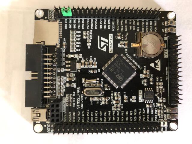 |
||||
| cdeagle Senior Member Joined: 22/06/2014 Location: United StatesPosts: 269 |
Hi Peter, I repeated the entire process again and the board is working now. I'm not sure what I did differently. I have a good memory. It's just short. |
||||
| matherp Guru Joined: 11/12/2012 Location: United KingdomPosts: 11599 |
New firmware version with STR2BIN() and BIN2STR$() and SYNC 2019-05-06_013740_ArmmiteF4.zip SYNC is a new command specifically for fast real-time programming. The syntax is SYNC [period] [,units] suppose you want to toggle a pin at exactly 100 micro-second intervals. If that pin isn't a PWM pin then the only way it could be done is to pad a loop with dummy statements until the period was correct. The syntax with the SYNC statement would be as follows SYNC 100,u do sync pin(17)=1 sync pin(17)=0 loop The SYNC command with parameters sets up a fast timer and stores the period. The SYNC command without parameters waits for the timer to reach the period specified and then resets the timer and returns. As this all happens in the firmware the timing period is extremely accurate. Valid units are: parameter omitted: the period is expressed in raw clock counts 1/84,000,000 seconds U or u: the period is expressed in microseconds M or m: the period is expressed in milliseconds S or s: the period is expressed in seconds In all cases the maximum period allowed is just over 51 seconds but, of course, for longer periods there are lots of other ways of doing this. The command is specifically targeted at short periods |
||||
| Page 1 of 16 |
|||||
| The Back Shed's forum code is written, and hosted, in Australia. | © JAQ Software 2026 |
