
|
|
Forum Index : Microcontroller and PC projects : Armmite F4: programming the firmware
| Author | Message | ||||
| erbp Senior Member Joined: 03/05/2016 Location: AustraliaPosts: 195 |
Hi, Got my board (and LCD screen) yesterday and have been trying to got it to work today. I got the firmware loaded ok after also experiencing some problems with the flaky USB connector as others have previously reported. But I cannot get Windows to recognize the Virtual COM Port after removing the BT1 jumper and changing BT0 to connect to GND. All Windows will do is report an error - see image below: 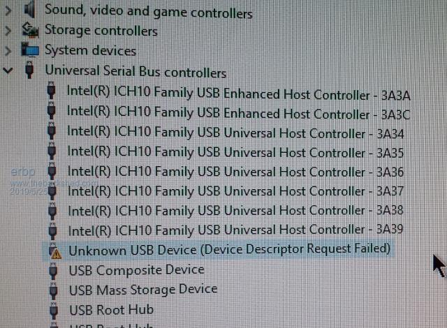 Initially I thought this was also due to the flaky USB connector but I have tried two computers and multiple USB cables (most known to work) all to no avail. I have even gone to the extreme of adding a replacement Mini USB connector - see below: 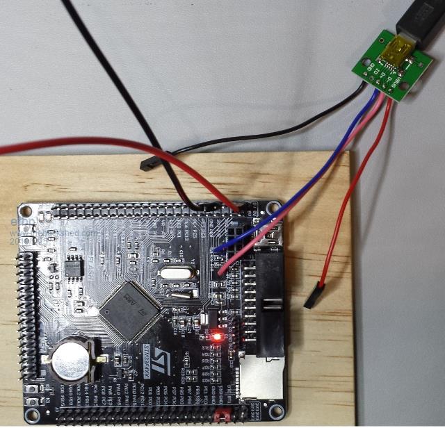 This arrangement has given a rock solid USB connection, and I have re-loaded both the original firmware file (2019-05-03_050415_ArmmiteF4.zip) and the updated one (2019-05-06_013740_ArmmiteF4) without any connectivity issues. Windows is quite happy to see the STM32 BOOTLOADER when the BT0/BT1 jumpers are set for firmware loading, but as soon as they are switched to just BT0 connected to GND - no USB connection! I have also tried using an external 5v power source (actually connected when the above image was taken) - no difference there either. I am thinking there must be something wrong with the chip or at least the parts that drive the non-bootloader mode USB. @MatherP - is it possible to get a copy of the firmware that has OPTION SERIAL CONSOLE ON set by default? I could then use a UART/USB module and connect to the console via the J6 serial connections. I assume the released firmware files have OPTION SERIAL CONSOLE OFF thereby enabling USB Console and disabling Serial Console via J6 and since I can't get a USB Console connection to work I can't change this option myself. PM me if you want my email address to email a copy of the file to. Any other suggestions as to how to investigate this further or resolve it would also be welcome. BTW - using Windows 10. Thanks, Phil. |
||||
| matherp Guru Joined: 11/12/2012 Location: United KingdomPosts: 10273 |
Attached 2019-05-25_191158_ArmmiteF4.zip . However, I suspect it may not work. The only reason I can see for your issue is that the main 8MHz Crystal circuit isn't working properly. I believe the bootloader uses an internal 48MHz RC circuit for the USB whereas the firmware uses the external crystal. If I am correct then the baudrate for the serial console also won't be correct and the processor may not even be running properly but please let me know what you find. |
||||
| erbp Senior Member Joined: 03/05/2016 Location: AustraliaPosts: 195 |
Hi Peter, Thanks for the modified firmware file. File loaded ok. I have connected a CP2102 USB to UART module connected to my PC. Armmite F4 is externally powered from a 5v source. Using MM Edit chat window to connect to the CP2102 COM port (COM5). On power up or pressing the RST button only the following message is displayed: Error: Invalid Pin Baud rate is set at the default 38400 and the message displays without strange characters or garbage, so looks like to serial port must be running at the correct baud rate so I guess the 8MHz crystal must be running ok. Any idea which pin it is failing on, and more importantly why that would happen? Thanks for you quick response and assistance. Regards, Phil. Edit: One other thing which may/may not be significant - D2 and D3 LEDs (bottom left corner) glow faintly all the time, except when the RST button is depressed. |
||||
| matherp Guru Joined: 11/12/2012 Location: United KingdomPosts: 10273 |
I think that can only mean that options area of the flash isn't getting programmed properly, which may mean the flash in general isn't programming properly. Since you have a USB/UART connected, try using it to program the firmware. Use STM32CubeProgrammer as before with BT0 set to 3.3V and select UART as the programming port. Do a complete chip erase and then re-program and see what happens This is normal as the pins are floating. The LEDs will control correctly when the pins are set as outputs |
||||
| erbp Senior Member Joined: 03/05/2016 Location: AustraliaPosts: 195 |
Hi Peter, Ok, tried that but the result is the same - it still reports "Error: Invalid pin." The full chip erase said it worked, and the firmware load said it was successful as was the verify. Can I use the STM32CubeProgrammer software to attempt to read the relevant portion of flash memory to see what it contains? If so I would need some pointers on how to do this and what address/area to check as well as what the output should look like. Otherwise it looks like I have a dud card/chip  |
||||
| seco61 Senior Member Joined: 15/06/2011 Location: AustraliaPosts: 205 |
Hi Peter. I was just using the BACKLIGHT command and noticed a slight issue: BACKLIGHT 0 results in the brightest backlight BACKLIGHT 1 results in the dimest backlight BACKLIGHT 99 results in the almost brightest backlight BACKLIGHT 100 results in no backlight Ahhh, some of the recent posts reminded me of what happened the very first time I loaded the firmware. The flash area associated with the stored OPTIONs seemed to be a little corrupted. With a OPTION LIST I noticed a "OPTION CONTROLS -2". Of course, silly me, did not think much about it until I attempted to run some code with GUI commands, OPTION AUTORUN and a WATCHDOG 1500 in the code. I got an error on the USB console stating something about the control number being invalid (must be between 1 and -2), then the watchdog kicked in which of course reset the USB console and by the time the USB serial port was available again the watchdog had kicked in and the loop continued with no way of breaking into the program... After reloading the firmware all was good (there was no OPTION CONTROLS in the list) and the program ran OK. Then, for "fun" I issued a "OPTION CONTROLS 100" command - this caused the unit to do some form of reset, I lost the USB console and the screen backlight returned to full brightness. After resetting my console software I could see that the OPTION CONTROLS is now listed by the OPTION LIST command. Regards Gerard (vk3cg/vk3grs) |
||||
| matherp Guru Joined: 11/12/2012 Location: United KingdomPosts: 10273 |
One last try: This version slows down flash access and disables cacheing. It is about 20% slower but does it work? 2019-05-25_213711_ArmmiteF4.zip |
||||
| seco61 Senior Member Joined: 15/06/2011 Location: AustraliaPosts: 205 |
Hi Peter. Is it possible to change the "OPTION SERIAL CONSOLE ON" command to also take a com port number (1-4)? Something like "OPTION SERIAL CONSOLE 4" to select com port 4 as the serial console. It would just save me moving some com ports around as all my programs currently use the com ports starting from 1 and incrementing as I need more - currently the most I use is 3 so being able to use COM4 for the serial console would be handy. Regards Gerard (vk3cg/vk3grs) |
||||
Chopperp Guru Joined: 03/01/2018 Location: AustraliaPosts: 1096 |
Hi Peter Small typo. RX & TX reversed. OK in the next listing. ChopperP |
||||
| erbp Senior Member Joined: 03/05/2016 Location: AustraliaPosts: 195 |
Unfortunately the error is still the same - no change  Guess I'll order another board and hope for better luck next time!! Thanks for your assistance anyway, much appreciated. BTW: If anyone is having trouble with the flaky Micro USB connector on the board and decides to add an outrigger one like I did (see the image in my first post on the previous page), there is an easier way than having to solder a couple of fly leads to components on the PCB. The USB D+ and USB D- signals use PA11 for D- and PA12 for D+ and these exist as pins on the J3 (right-hand side) connector - so you can just connect to them there using dupont connectors - no soldering required (well maybe at the replacement USB connector end). |
||||
| CaptainBoing Guru Joined: 07/09/2016 Location: United KingdomPosts: 2170 |
I am still using the USB console on my tests but I find that this is pretty much a toggle. If I reset the board, no COM24 (in my case), reset again, COM24 returns... GOTO 10. I also get this behaviour with resets under firmware control - this was precisely what was happening with my WATCHDOG woes earlier... and because of the way the USB console buffers the output, once it was full, I think the print command was blocking which caused the watchdog to reset everything... and that was my "reset loop". Although I am still using it on my desk, I am finding lots of reasons to leave the USB console behind - which fits with my long term plans anyway so I am good. I have learned to live with it for the moment but I do intend to go down the J6 route and turn off the USB serial as I use a 3.5mm jack socket/plug system that use everywhere which just needs a raw serial link and the USB conversion is done at the PC/Phone/Tablet end - which is like you found, rock solid. |
||||
| vegipete Guru Joined: 29/01/2013 Location: CanadaPosts: 1129 |
At last an F4 board plus LCD panel arrived in my mailbox. 10 days? Hah! After a bit of dorking around with st.com access and updating Java, STM32Cube ran but all was not quite well. The USB jack on the board is flakey and only works with certain side loads applied to the plug. Hard to type when one and a half hands are busy holding the plug just right. However, after some mucking about, I successfully programmed the firmware and played a bit. Looking Good! I suppose I'll shift to using J6 for the console also. I gather the firmware can only be programmed through the USB port, unless I start connecting ST-LINK programmers? Kudos to matherp for on-going fantastic program development! Well done! Visit Vegipete's *Mite Library for cool programs. |
||||
| vegipete Guru Joined: 29/01/2013 Location: CanadaPosts: 1129 |
Hmmmm, some careful use a small piece of emery cloth inside the USB jack on the board has improved the connection tremendously. Even the crummy USB cable provided with the boards works hands free now. Corrosion is not your friend! Visit Vegipete's *Mite Library for cool programs. |
||||
| erbp Senior Member Joined: 03/05/2016 Location: AustraliaPosts: 195 |
No, you can also program the firmware via the J6 Serial Console connection - I did this last weekend as part of trying to resolve the problem with my F4. Assuming you have everything setup for using the Serial Console - OPTION SERIAL CONSOLE ON and a UART/USB module attached to J6, when you run STM32CubeProgrammer, select the UART connection method instead of USB. This is an option in the drop down list that contains the USB option. Everything else works the same way as the USB method, just that it will be slower (depending on the baud rate). Still quite doable though. So you can get by totally without using the flaky on-board USB connector. Another alternative is to add your own USB connector - you will have no chance of replacing the existing one as the nearby connectors make it impossible to even attempt to unsolder (maybe a heat gun **might** work) but then it would be an extreme challenge to solder in a replacement one. Better to just ignore the existing one and add an extra one on a separate small board - see my image on the previous page and description above about being able to do it entirely using dupont connectors and not having to solder on fly leads for the D+/D- connections. Cheers, Phil. Edit: Ignore my reference to needing OPTION SERIAL CONSOLE ON to be able to load the firmware via J6. When loading firmware the unit is running the bootloader, and the MMBasic options are totally irrelevant at that time. So you just need to UART/USB module connected to J6 and select UART as the connection method in STM32Cube. |
||||
crez Senior Member Joined: 24/10/2012 Location: AustraliaPosts: 152 |
I have been playing with my F407 board and after replacing the supplied USB cable, all is good except.... Time$ reverts to 00:00:00 after power-down. I have checked the voltage at VBAT, pin 6 of the processor and it is 2.9v. Any ideas? mm.ver=5.0506 |
||||
| CaptainBoing Guru Joined: 07/09/2016 Location: United KingdomPosts: 2170 |
Hi Crez. One of my two boards had the same - it was a dead coin cell in my case. 1.6V which dropped rapidly to 0.4 when tested. replace it with a fresh 3.3V CR1220 and you should be good to go. Although you have 2.9V it is still less than ideal... if it is this then it is a cheap/quick fix. Good luck hth |
||||
| crez Senior Member Joined: 24/10/2012 Location: AustraliaPosts: 152 |
Thanks. The datasheet suggests it should operate down to 1.65v. CR1220 batteries are a bit rare here so I might try clipping something across it as a test. |
||||
| matherp Guru Joined: 11/12/2012 Location: United KingdomPosts: 10273 |
The circuit on the PCB has a dual common cathode diode (Q1) connecting the battery and the 3.3V supply to VBAT. That diode will have a drop across it so the 1.65V will be 1.65 + Vf However, I would suspect the diode is missing or faulty. Personally I remove the diode and bridge the VBat supply across it |
||||
| crez Senior Member Joined: 24/10/2012 Location: AustraliaPosts: 152 |
with two AA's in series clipped into the battery socket I now read 3.09v at pin6 when powered down and 3.25v powered up. Still no time keeping. |
||||
| matherp Guru Joined: 11/12/2012 Location: United KingdomPosts: 10273 |
Ignoring that the clock resets does it run? Does time$ increment when powered? |
||||
| The Back Shed's forum code is written, and hosted, in Australia. | © JAQ Software 2025 |
