
|
|
Forum Index : Electronics : nano to totem pole Mosfet drivers
| Page 1 of 2 |
|||||
| Author | Message | ||||
| Tinker Guru Joined: 07/11/2007 Location: AustraliaPosts: 1904 |
Has anybody tried that yet? I'm having no luck trying to swap the EG8010/IR2110 control board with my nano control board. This eats up HY4008's  . .I know my nano control board works, see inverter #5 thread. I know my EG8010 control board works - it has been running my inverters for quite some time now. So the problem must be with the totem pole drivers, the only thing that's different at the Mosfet side. Most likely I did something silly and just cannot spot it, so I'm eating humble pie and ask the esteemed collective expertise here for advise  . .This is the nano inverter without totem pole drivers: 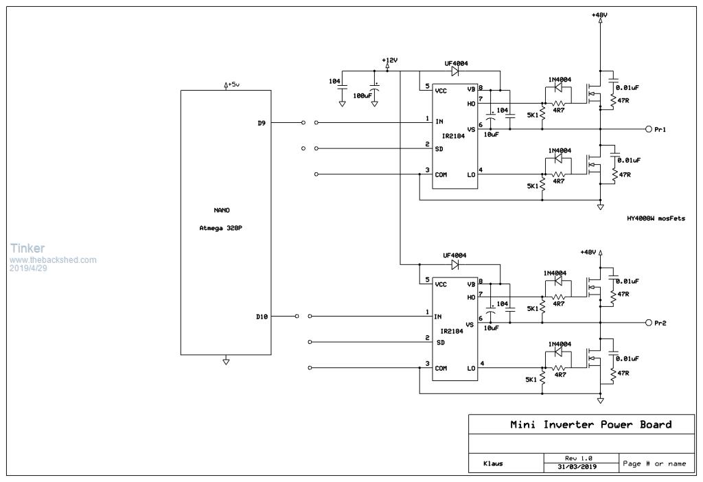 And here is the original EG8010/IR2110 control board. 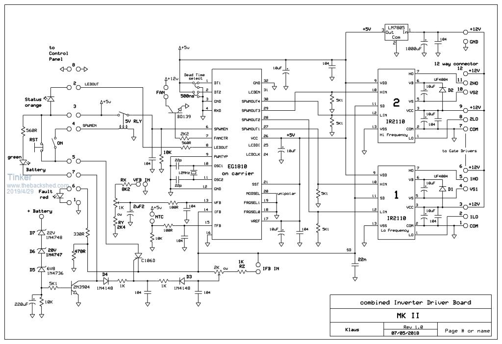 To be replaced by the nano board, the totem pole drivers are at the right side and these are the same the EG8010/IR2110 board connected to: 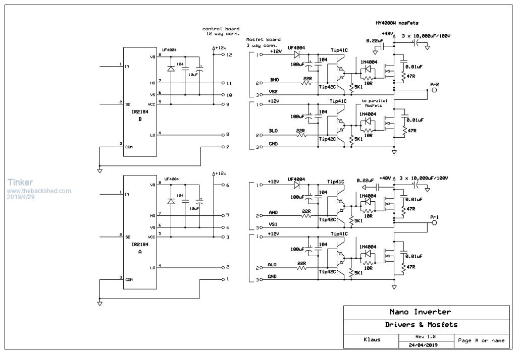 Note the connections are done via a 12way header cable that has 4 x 3way headers at the far end. I use the same cable, making sure the connections on the new nano control board correspond. I copied the charge pump +12V supply as it was at the IR2110 drivers, did I go wrong there? Klaus |
||||
| Solar Mike Guru Joined: 08/02/2015 Location: New ZealandPosts: 1171 |
Looks like the A\B H0 totem pole V+ 12 volts supply if derived via the charge pump should go to the VB output of the IR drivers (Pin8), you have it wired to Vcc +12v. Cheers Mike |
||||
| Tinker Guru Joined: 07/11/2007 Location: AustraliaPosts: 1904 |
Thanks for that Mike, you confirmed my suspicion. Unfortunately have to wait now until the next batch of HY4008's arrives to confirm. This gives me time to modify that PCB, its a blessing they are so cheap in the 100x100 size. The strange thing is, if you look at the original EG8010/IR2110 schematic, the totem pole used there (not shown on drawing) has its own +12V and not from the VB at the IR2110's. It works fine there. I guess the IR2184's are different. Klaus |
||||
| poida Guru Joined: 02/02/2017 Location: AustraliaPosts: 1439 |
For what it's worth, I have had good results driving Madness's power board (with totem pole drivers) with the nanoverter. No modifications were needed. I've confirmed the excellent isolation of the power stage's EMI from the IR21844 gate drive outputs. So clean now and they stay within IR specifications. Mark (renewableMark) is of course happy with his nanoverter/Madness setup. wronger than a phone book full of wrong phone numbers |
||||
| Tinker Guru Joined: 07/11/2007 Location: AustraliaPosts: 1904 |
AFAIK Mad's totem pole driver is no different from mine, its the connections to it I suspect are different. Is tinyt's schematic of mad's power board a true copy or is there a newer schematic in existernce? I would not mind to double check as I plan to swap all the EG8010 control boards for the nano versions. Klaus |
||||
| tinyt Guru Joined: 12/11/2017 Location: United StatesPosts: 469 |
Sorry, I did not make a schematic of mad's power board. I only made the schematic and pcb gerbers for the nanoverter controller. |
||||
renewableMark Guru Joined: 09/12/2017 Location: AustraliaPosts: 1678 |
My nano control board was a direct swap over with the Mad power board. Runs the house. Maybe give Mad a call/email or for $30 just buy one of his power boards. Cheers Caveman Mark Off grid eastern Melb |
||||
| hugocamaras Newbie Joined: 12/04/2019 Location: BrazilPosts: 24 |
Tinker/Poida, Would it be feasible to make an extra card with that Toten driver to use on an Ozinverter / Clockman power board? |
||||
| hugocamaras Newbie Joined: 12/04/2019 Location: BrazilPosts: 24 |
Tinyt, can you publish the files for me to make the Madness power board with totems? Of course, if that's allowed by Madness. I would like to buy Madness cards but it would be so expensive for me because I live at the end of the world (Brazil). Thankful. |
||||
| tinyt Guru Joined: 12/11/2017 Location: United StatesPosts: 469 |
Hi Hugo, Sorry, I also did not do the pcb gerbers of the Madness power board. |
||||
| wiseguy Guru Joined: 21/06/2018 Location: AustraliaPosts: 1225 |
I dont concur that you made an error by not joining the VB to the totem pole+. If both charge pump diodes are installed, both nodes should be near identical as they should both charge to the same +level - it cant do any harm, but I am not confident it is actually fixing a problem. The buffer stage only needs a ground referred input drive level to function correctly IMO. Whilst a buffer stage helps to drive the FETs better, the TIP41/42 would not be my first choice either, they have a turn on time of 0.6uS, turn off 1uS, storage time is not given but would also be slow at >1uS. When dealing with FETs I dont like stuff switching too slowly as dead times can be impacted. For instance the 2SA2210 has turn on 60nS, storage time 220nS and turn off 20nS. That is 10 times faster on, 50 times faster off, 5 times faster in between, a gain ~ 100 and 20A current capability all for $1.50. If at first you dont succeed, I suggest you avoid sky diving.... Cheers Mike |
||||
| Solar Mike Guru Joined: 08/02/2015 Location: New ZealandPosts: 1171 |
I agree, those Tip 41/42 are pretty slow, they really were only used in older style audio amplifiers and are now dirt cheap. Faster devices would be beneficial, initially their use was suggested as the circuit was cloned from an existing Chinese 6KW inverter board, which used a pair mounted a CM or so away from each group of parallel mosfets, all of which were many CM's away from the IR driver chips, giving at least some improvement in drive; I think we can do better... Cheers Mike |
||||
| wiseguy Guru Joined: 21/06/2018 Location: AustraliaPosts: 1225 |
By being slow they also helped to swallow the unpopular glitch I found from the EG8010 when not using the anti cross conduction transistors. So for EG8010s they arent all bad and maybe improved things - its a shame that some Isotop (SOT227 packages and TC4452's etc that some pioneers here were trying to use found the glitch and died a sad death' I am currently working on a new Mad style Power Board for use with the nano that will use all isolated supplies and optos to completely galvanically isolate the power stage from the nano board (except for a common ground to measure VBat). Mike (or anyone else that cares to chime in) do you have any experience with a negative voltage applied to the gate when not being driven on, to help mitigate against glitches from dv/dt and CGD issues turning the FET on? I know IGBT's use a pseudo ground and drive with maybe 18V - their resultant output is 12V drive and -6V on idle (both WRT ground) - it is messy and doenst feel quite right - there must be a better way ? If at first you dont succeed, I suggest you avoid sky diving.... Cheers Mike |
||||
| Tinker Guru Joined: 07/11/2007 Location: AustraliaPosts: 1904 |
And I agree with you Mike, yes I did just copy the totem pole arrangement I saw posted on this forum somewhere sometime ago. Can you suggest a suitable fast TO220 NPN, PNP replacement with a BCE pinout? If they are easy to get and not cost too much I'm happy to swap those slow transistors. What is odd is, the mad board's totem pole drivers appear to work with the nano board. Too bad there is no schematic (I do not do schematics I hear somebody mumble  )available so I could check what's different. )available so I could check what's different.Mark, your suggestion of buying a mad power board is not being considered, this would involve re building the entire inverter from scratch  . .Klaus |
||||
| Solar Mike Guru Joined: 08/02/2015 Location: New ZealandPosts: 1171 |
I have never used -ve gate voltages on mosfets so cannot really comment whether doing so would improve matters with these dv/dt glitches. Always seems suggested when using IGBT's. Some publications suggest adding a small capacitor between the gate and source to absorb the glitch pulse caused by induction through the mosfets internal miller capacitance, I don't like this method as extra drive power is required to turn it on and off, perhaps ok to use with low charge input versions. If the output impedance of the mosfet driver is very low, and the driver is a cm or so away from the device, then the gate circuit is generally sufficiently damped and less susceptible to any miller induced turn on. So use 1 driver chip per mosfet and split the damping resistor to the gate to a low value 1 to 3r for the on circuit and 0r for the off part. Some driver chips like the TC4452 have a split output that allows this scheme; similar effect (not as good) achieved by use of a schottky diode across the gate resistor. Costs start to add up if a 1:1 driver\mosfet is used, depends on the situation and the type of mosfets used, a 1:4 ratio would probably work ok with the mosfets people here are mostly using, or use the low cost ZXGD3005 series in a 1:1 ratio (small and fiddly however) when using the higher input capacitance IR mosfets. Certainly using anti-cross conduction transistors is a good improvement and going to an all quadrant isolated drive scheme using either opto-isolated or digital isolator chip would be a vastly better improvement for preventing ground induced spikes and reliability in general. Cheers Mike |
||||
| renewableMark Guru Joined: 09/12/2017 Location: AustraliaPosts: 1678 |
Just give Mad a call, he really is very helpful, prob take 5 min to sort it out. Cheers Caveman Mark Off grid eastern Melb |
||||
| Tinker Guru Joined: 07/11/2007 Location: AustraliaPosts: 1904 |
Thank you for your input, agree the TIP41/42 are slow but they were at hand. Now, I looked up your suggested 2SA2210 and yes, it switches fast. But I need a complimentary pair of transistors and could not find one with my limited search knowledge. So I ordered MJE15032/33 transistors, they go to 30MHz but no on/off times shown on the data sheet I have. I suppose they are an improvement? Klaus |
||||
| wiseguy Guru Joined: 21/06/2018 Location: AustraliaPosts: 1225 |
Mike Thanks for the reply - I think I have a solution I will post here soon. Sorry Klaus I got sidetracked after starting an answer to you. The MJ15032/33 have to be faster switches than the TIP 41/42 - I spent hours earlier today researching good driver transistors, I gave up on "old technology" parts as there were never (well rarely) rise and fall and storage times shown A good complement to the 2SA2210 part would be a 2SC6082, it doesnt really matter that one is a 15A the other is a 20A part. The parts I recommend for a direct replacement with vast switching time improvement and gutsier drive is this pair 2019-05-01_004603_EN6913-D.pdf They are in a smaller TO251AA which is like a malnourished TO220 & around 80cUS ea If at first you dont succeed, I suggest you avoid sky diving.... Cheers Mike |
||||
| Tinker Guru Joined: 07/11/2007 Location: AustraliaPosts: 1904 |
Thanks, where did you see them? Aliexpress had the 2SA2040 about 10 times as expensive than the 2SC5707. I'm not familiar with the TO251AA style, is the pin spacing close to 0.15" to fit into my terminals? I should have another look at the specs, there might be a drawing . Klaus |
||||
| wiseguy Guru Joined: 21/06/2018 Location: AustraliaPosts: 1225 |
Here is the gate drive that drives the gate to ~ 11.5V and when off it holds the gate at ~ -4.5 (note a 12V supply in lieu of the 5V could be substituted for more serious neg bias). I will breadboard it soon to prove the concept and switching speed etc. I decided to do a discrete buffer instead of using the MIC4452 so I could incorporate a gate clamp in the absence of power. Only the Low side FETs for both lower legs of the Bridge stage will have the negative bias/clamp circuit and they would both share the same bias supplies. I know its a bit ugly but all the bits actually do stuff. It is essentially an emitter follower current driver and an active gate clamp. I believe it will survive a turn on event without charging the caps first (cant say how the contactor would like it though) 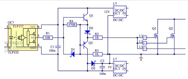 If at first you dont succeed, I suggest you avoid sky diving.... Cheers Mike |
||||
| Page 1 of 2 |
|||||
| The Back Shed's forum code is written, and hosted, in Australia. | © JAQ Software 2025 |
