
|
|
Forum Index : Solar : Biggest mistakes made when new to solar
| Author | Message | ||||
LadyN Guru Joined: 26/01/2019 Location: United StatesPosts: 408 |
Hey! Thanks for pitching in. Appreciate it. With your experience I can get further than on my own. Here are my thoughts: I want to design for the AC rated heating elements that's available everywhere. NO DC rated elements at all. The ones I've seen are typically 240V AC, 4kW, so I would expect the current draw to be 4000/240 = 17A To draw 17A@240V, the nominal resistance needs to be 14E. At 30V, a 14E element can let through 30/14 ~= 2A. This would generate 4 * 14 = 56W. After a whole day of running, the water will be barely warm. Heater tank losses being 1kWh, there's no meaningful effect. Now, connecting the 1kW, 130Voc PV array directly to the AC rated heating elements wont work either. The 14E elements will likely make the PV array drop to Vload of say 50V. At 50V, a 14E element can let through 50/14 ~= 4A. This would generate 16 * 14 = 224W. After a whole day of running, the water will maintain temperature after accounting for heater tank losses of ~1kWh. But there's no meaningful heating effect, which is want we want. So the solution is to ensure the PV array are never directly connected to the AC rated heating elements and there's a DC Convertor in the middle. As a result, I am learning about Linear Current Boosters. The PV array is a current source and the heating elements work off current, so we need to work in the current domain? That's what I think. Once I have learned about LCBs, I will make one and possibly feed one through an ESP32 controlled full HBridge to the AC rated heating elements. |
||||
| Solar Mike Guru Joined: 08/02/2015 Location: New ZealandPosts: 1124 |
If your HWC cylinder has dual elements, then either place them in series for higher DC voltages or in parallel for low dc; this may give a better match to your PV array without having to build a mppt current booster. Or get specific low R DC elements here , not cheap though, I have seen 50v dc load diversion elements also advertised. If you cannot get anything suitable, then the easy alternative is some sort of pulsing current dumper; charge a big cap to some nominal voltage and dump across the element with a mosfet switch, this will put a sizable pulse into the element, the voltage across the cap will drop below a set point, switch opens and process repeats; speed determined by the amount of sun on your panels. Its often a good idea to do this on a pre-heater HWC, that feeds warm to hot water into the cold inlet of your main existing cylinder, that otherwise remains unmodified. Cheers Mike |
||||
| BenandAmber Guru Joined: 16/02/2019 Location: United StatesPosts: 961 |
I agree with solar Mike I have seen a scale somewhere that tells you how many watts at how many votes for each different regular off the shelf hot water heater element With nothing in between besides fuses be warned i am good parrot but Dumber than a box of rocks |
||||
yahoo2 Guru Joined: 05/04/2011 Location: AustraliaPosts: 1166 |
I am planning on using underfloor heating cable and wrapping a band around the tank for my off-grid DC heating, the cable length is critical to match 28 volts. My grid connected solar AC is passed through a power router (priority HWS over grid feed in) when it is not on a reduced tariff rate. I'm confused, no wait... maybe I'm not... |
||||
| BenandAmber Guru Joined: 16/02/2019 Location: United StatesPosts: 961 |
Yahoo2 That is a very interesting subject I would like to do something like that on my RV So if you don't care please share any information that you have on the subject It doesn't matter to me if you do it here or elsewhere I would just like to read about your progress be warned i am good parrot but Dumber than a box of rocks |
||||
| hotwater Senior Member Joined: 29/08/2017 Location: United StatesPosts: 120 |
in the US, 2,000W 120V elements are cheap and common. They work well with 60-90V arrays. Those 6 gallon 1,500W 120V point of use heaters are ideal for a RV. I have an ECOsmart as my primary tank and 1KWH raises 6 gallon 60F, a convenient number to remember. Here is a low cost linear current booster setup that charges batteries and also heats water on a 60V array. The water heater green board allows the use of the water heaters mechanical thermostat to switch the high current DC without any issue with contact arcing. 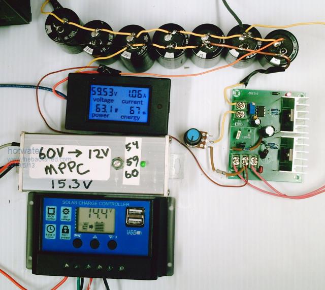 |
||||
| LadyN Guru Joined: 26/01/2019 Location: United StatesPosts: 408 |
6 gallon is not very useful for our house. 50 gallons is my objective. Thank you! The half bridge inverter board is a brilliant idea to get the AC like zero crossings! In your picture I see: 1. Input from PV comes in and there are two parallel paths - the modified MPPC 12V buck converter and the series PWM charger 2. 7x 1200uF, 100V DC Caps for a total of 8400uF are connected via a diode to stop inrush backfeed that can damage the PWM charger 3. This cap bank sources power from the array when the series PWM charger is open and feeds the modified MPPC 12V buck converter, which powers the 12v half bridge inverter board on the right So there are 2 ways you can wire this up: i. feeding 12v DC to your HWS The 2kW 120V elements that are cheap and common should present a current draw of 2000/120 = 17A. To draw 17A@120V, the nominal resistance needs to be 7E. At 12V, a 7E element can let through 12/7 ~= 2A. This would generate 4 * 7 = 28W. Unless my calculations are absolutely off, there's no meaningful effect on heating water with 28W even if I had sun for 10 hours. so this is not what you're doing. which brings me to.... ii. Other way being the 12V buck converter is there JUST to power the 12v half bridge inverter board and that switches the 60V PV array voltage directly to the 2kW 120V elements When the buck converter sees that the panel voltage is dropping below set threshold, it turns itself off, turning off the inverter board in turn. This option has a lot more potential feeding the 60V panel voltage directly to the 2kW 120V elements At 60V, a 7E element can let through 60/7 ~= 9A. This would generate 81 * 7 = 567W. With that power, a lot of hot water can be generated on a good day! However, I cannot see how that 567W can be sustained - as soon as the cap bank is discharged, the elements will be essentially directly connected to the PV array. This would shutdown the buck converter and the elements would have no power. This allows the caps to charge until they reach buck's threshold and the whole process repeats. A lot of oscillations and stress on that cap bank I think? Maybe that's how all linear current boosters operate and I have to take that into my stride buying caps as they die but I wonder what the effective power delivered would be? |
||||
| BenandAmber Guru Joined: 16/02/2019 Location: United StatesPosts: 961 |
That is neat hot water Thanks for sharing LadyN I think the battery keeps it from turning off and on be warned i am good parrot but Dumber than a box of rocks |
||||
| hotwater Senior Member Joined: 29/08/2017 Location: United StatesPosts: 120 |
NO diode (I don't see one)unless you want to put one in. It is generally not needed unless the heater is in parallel with a PWM controller directly connected to the panels. In that case it harvests only when the PWM is in the off cycle. I have 30 gallons of water at the camp. This is enough for showers and dishwasher. This also runs the heated dry on the dishwasher. This year I am also adding another 30 gallon tank for clothes washer this year. I do have excess power that I am not able to use because of 60V panels I have. 6 gallon tank was to show how even a vary small camp system can have hot water for free. A wasted effort since no one can understand the theory of operation. The water heater circuit could run a DC pump just as easily as a linear current booster. The green board is completely self powered from the 60V array and it only takes 15ma. The board has under voltage lockout so a very clean startup. The mechanical thermostat is between the panels and the capacitor bank and has about a 400 ohm resistor bridging the contacts. This keeps the capacitors always at the power point voltage. The heater control acts like a shunt regulator. Therefore, the differential voltage is never more than 30V not violating any laws of nature. This is the when the contacts open. 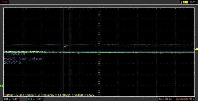 In theory, both FET in parallel operate half the time and share any heat dissipation usually less than 2W. At low light level it favors one FET due to startup. It is constantly checking any time the voltage on the capacitor bank drops and that is around a quarter volt with a 60V panel. It can be made any voltage depending on FET. This was just a stock photo for how someone can get into solar cheaply. (90% of benefits of a full MPPT for $10. Small camps generally don't need any more than 10A. Big panels allow the system to work even in cloudy weather. |
||||
| LadyN Guru Joined: 26/01/2019 Location: United StatesPosts: 408 |
Yes, for the harvesting to work, the cap bank has to be in parallel to the PWM controller right? Also, since the cap bank stores a significant amount of energy, we need to ensure it does not backfeed into the PWM controller or the PV array, right? So, how is all of this being achieved without a blocking diode or a power rerouting switch? I won't say it's a wasted effort - you're assuming a lot on the part of the reader. If the reader was competent enough to understand the whole design from pictures and an explanation, they won't need the pictures and an explanation to begin with: they could have come up with it on their own. In that case, the pictures just verify what they came up with. For someone who lacks the deep understanding necessary to come up with your design from scratch, a blueprint of the complete system is critical. A schematic of the complete system really helps understand what's going on. If you have a schematic of the picture you showed, that would REALLY help. My brother who's been in construction for over 20 years can guess down to the studs how a house is setup just by standing outside the house. A blueprint verifies what he had in his mind. For someone building a house without construction experience, the opposite method is necessary - the blueprint helps them take the path and leap forward. what is the buck converter doing there then? If the green board is independently powered, a TL431 based comparator could tell it when to stop feeding the elements when the PV voltage starts to drop below threshold, right? Is this checking being done by the green board or the buck converter? At what voltage? 10A from 12V nominal panels produce much less power than a 10A, 30V nominal grid panel vs. a 10A, 3x 30V nominal grid panel Thank you for the details and I hope to plug in the gaps for someone trying to reproduce the useful system you've designed. |
||||
| hotwater Senior Member Joined: 29/08/2017 Location: United StatesPosts: 120 |
I've posted so much that I am unaware of what is posted where. It seems like the schematic should be on this board somewhere. Given the worldwide audience on several venues it is disappointing that only one person has been able to build a system. That was a farmer with absolutely no technical training. I've sent several working semi assembled systems to people and none they have ever put them into a system. Yea, by any measurement it has been a wasted effort. The buck converter is only for the PWM controller and it acts like a LCB with a voltage limit. There are a lot of 48V systems out there with just a PWM controller that water heating could be used with as long as there is an isolating diode to prevent the capacitor bank from dumping into the battery. One of my heaters operates off a "36V" string that provides about 50V. With battery voltage elements it could even be used with a 12V system. My camp with a fridge hardly ever goes above 12A charging. Typically it is far less than 5A most of the day 500W of panels is a good match for a camp like that. Bigger panels are bought so the system can still work in cloudy days when only 100W can be produced. So, a $4 charge controller is all that is needed with a $5 modified buck converter and super cheap grid tie panels. Few analyze what is actually needed for a working system. The green "300W inverter" $6 board is a convenient breadboard for making a nice looking system. It used to come with 75N75 FET which were good for a 60V system. This FET is likely still available from vendors offering a 24V version. Now the boards come with a 50V FET requiring replacement. Still not a bad deal for everything else you get. The picture below is one I built from an obsolete out of production bare board. A little perf board would be an easy build. Getting the heat sinks, terminals etc would probably run as much as the $6 board. 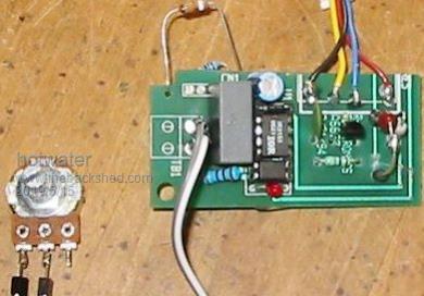 A TL431 is used in each to shut the devices off when panel voltage drops. The heater needs about 25ma to keep alive and the capacitors at the set voltage. At that point is is a shunt regulator using the resistor across the thermostat. |
||||
| yahoo2 Guru Joined: 05/04/2011 Location: AustraliaPosts: 1166 |
 previous discussion was in march. schematic included previous discussion was in march. schematic included PV solar water heater I'm confused, no wait... maybe I'm not... |
||||
| hotwater Senior Member Joined: 29/08/2017 Location: United StatesPosts: 120 |
Elvis has left the building. I'm packing up and moving. Also have a bunch of paperwork I've been avoiding. As there is no active building of this, I am discontinuing internet activity till sometime in June. See you then. |
||||
| LadyN Guru Joined: 26/01/2019 Location: United StatesPosts: 408 |
Ok, good luck! I am definitely going to replicate your ideas - just don't have all the pieces together yet. Right now I'm focused on understanding and building a current and voltage limiting MOSFET based AC/DC switch that works over WiFi. Will be happy and excited to see you back - I'll have a lot of questions for you by June for sure! Take care |
||||
| Warpspeed Guru Joined: 09/08/2007 Location: AustraliaPosts: 4406 |
The idea behind a 6 gallon point of use water heater is that it is installed right below the hot tap with about one foot of pipe. The water feed into that six gallon tank comes from the main storage hot water system that may be located a very long distance away in a really large house. So instead of opening the hot tap and waiting 30 seconds for some hot water, its right there in about one second. Those small 6 gallon tanks are ideal for an RV, or installed in a garage or back shed, where you might only need a very limited supply of hot water for maybe washing your hands. Cheers, �Tony. |
||||
| Solar Mike Guru Joined: 08/02/2015 Location: New ZealandPosts: 1124 |
Absolutely; we used to wait over 30 seconds for sufficiently hot water to arrive at the kitchen sink taps. Fixed that problem by mounting a 180L tank in the garage off the floor directly under the sink, short pipe run to the sink mixer and dish washer. This tank is disconnected from the main HWC in the house and has 2 sqm DIY solar hot water panels mounted on posts outside the house keeping it hot. Booster electric element mounted in the tank 300mm from the top keeps the very top heated at 60c. Hot water panels are easy to make and 1/4 the size of PV for same heat output. Cheers Mike |
||||
| BenandAmber Guru Joined: 16/02/2019 Location: United StatesPosts: 961 |
A  Warpspeed check out this heat sink it reminded me of you What would be wrong with using real high amperage mosfets like the 360 amp ones I know they won't do the 360 amps in real life but could you not get by with fewer of these so would have less paralleling And could a person submerged the whole inverter board in Transformer oil to keep it cool be warned i am good parrot but Dumber than a box of rocks |
||||
| yahoo2 Guru Joined: 05/04/2011 Location: AustraliaPosts: 1166 |
if it is any consolation I have cobbled together some units to drive remote pumps and stuff for some farmers. I got them running with what I had laying around, I really need to buy some bits and do a better job. I'm confused, no wait... maybe I'm not... |
||||
| hotwater Senior Member Joined: 29/08/2017 Location: United StatesPosts: 120 |
Fired up the camp water heater today without all the panels even installed. The fridge was also started with 54 drink bottles each 17oz for cold ballast in the chest fridge and that ran a lot. Still had hot water way before noon. The 6 gallon tank set at highest temp shut off at max temp using 1041WH of solar. There is also a 10 gallon feed tank in series and that is over 100F now. Having a small primary tank fed with pre heated water gives a really fast response with only a couple hundred WH of solar needed. I'll be adding a 40 gallon water tank just for laundry. You just can't imagine how well this system works. |
||||
| LadyN Guru Joined: 26/01/2019 Location: United StatesPosts: 408 |
I sure can imagine which is why I am trying hard to understand the design and replicate it. Schematics are important - after which the pictures you posted will be helpful, but for a rank beginner like me, reversing schematics from pictures is a bit too involved. 1. So you have a fridge and a chest fridge - are they AC or DC ? 2. Do you run them off inverters? 3. What kind? 4. I had been excited on reading about DC compressors but on digging deeper they turned out to be AC compressors with an integrated inverter sold at a heavy (10x - 15x!) markup. I can build a Warpverter at that price and power a whole house |
||||
