
|
|
Forum Index : Microcontroller and PC projects : MT3608 problems
| Author | Message | ||||
OA47 Guru Joined: 11/04/2012 Location: AustraliaPosts: 1050 |
I have a need for some boost modules to activate some 12-50V DC pulse solenoids from a mite. I have chosen to use the MT-3608 pictured. 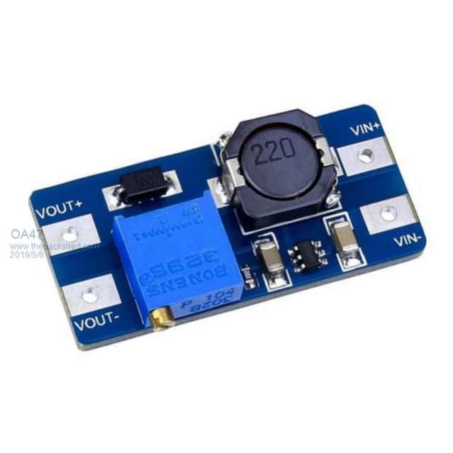 I have placed a 4700uF cap across the output to provide the current needed to latch the solenoid for a 150ms pulse from a relay. The problem is that the in-rush current to the cap is destroying the chip and letting the smoke out. I think that I need a resistor between the module and the cap. Can anyone give me an idea of the value needed that would limit the current to the cap and also provide a timely charge up time? OA47 |
||||
palcal Guru Joined: 12/10/2011 Location: AustraliaPosts: 2039 |
Have a look HERE "It is better to be ignorant and ask a stupid question than to be plain Stupid and not ask at all" |
||||
| Volhout Guru Joined: 05/03/2018 Location: NetherlandsPosts: 5986 |
What are you exactly trying to do ? Boost 3.3V to 50V ? Or boost 12V to 50V ? I assume the later. You mention inrush current destroys the chip. Not sure what chip type is used. Typically in a boost convertor the current flows through inductor and diode during inrush, and not through the chip. But the inrush current WILL saturate the inductor if no current limit is applied. This may destroy the chip. The boost convertor will have a specification about the current it can deliver. Looking at the SOT23 chip, it will be something like 1A max input current. If you convert from 12V to 50V (roughly 4x) the max output current will be 250mA. A suitable resistor would be 50V/250mA = 200 ohm (220 ohm). Please note that this resistor will consume peak power of 12.5 watt. This is not continuous, so a 5 watt wire wound resistor will be fine. Charge time of the capacitor (99% full) be 5T = 5 x R x C = 5 x 200 x 0.0047 = 5 seconds. Hope this helps Volhout PicomiteVGA PETSCII ROBOTS |
||||
| OA47 Guru Joined: 11/04/2012 Location: AustraliaPosts: 1050 |
Sorry for the lack of info. I am feeding the boost module with 12V (But could get down to 10V) and setting the output to 18V as this seems to be enough to reliably switch the solenoids. I could probably allow for around 1.5sec of charge time. OA47 |
||||
| BrianP Senior Member Joined: 30/03/2017 Location: AustraliaPosts: 292 |
Hi OA47 We need to know the max current rating of the module. Then we can work out what resistor is needed to limit the current. OHM's law - Volts (from module) / max current allowed (amps) = resistance needed. eg. for 50 volts out & 50mA current the resistor would need to be 50/.05 = 1000 ohms. A good idea to err on the side of caution & use a higher resistor value, just be aware that the higher the resistance the longer the charge time of the capacitor. Depends on how often you need to trigger the solenoid. Use @palcal's link to work out the charge times. Cheers Brian P. edit - Volhout beat me to it... |
||||
| twofingers Guru Joined: 02/06/2014 Location: GermanyPosts: 1767 |
Hi Graeme Maybe the back-EMF is the issue. Michael causality ≠ correlation ≠ coincidence |
||||
| OA47 Guru Joined: 11/04/2012 Location: AustraliaPosts: 1050 |
I should add the note that the chip is letting out the smoke on power up not when the solenoid is attached. Thanks for the feedback, I will insert the appropriate R with enough W and see how it goes. OA47 |
||||
| twofingers Guru Joined: 02/06/2014 Location: GermanyPosts: 1767 |
Hmm, and you are trying to activate the "12-50V DC pulse solenoids" with about 20V? I guess the maximum output voltage (MT3608) is 28V. causality ≠ correlation ≠ coincidence |
||||
| robert.rozee Guru Joined: 31/12/2012 Location: New ZealandPosts: 2541 |
hi, can you post some more details of the solenoids - what are their rated voltage, coil resistance, perhaps even a photo may help. if a solenoid is only activated occasionally, say every couple of seconds, you can have a current-limited supply feeding a reservoir capacitor. the capacitor will ensure plenty of current to initially pull in the solenoid, with the backing supply providing enough volts/current (less than the initial requirement) to hold the solenoid in. quite seperately, you'll then have a switching trasistor to turn on the solenoid itself: 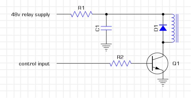 in the above, pick C1 to provide enough 'oomph' to pull the solenoid in, R1 high enough to not exceed the peak current output from your boost converter yet low enough to not drop too many volts when Q1 is on, and make R2 around 680 ohms or so so that Q1 is fully saturated when activated. btw: use a boost converter based on the LM2577 or similar in a TO-220 sized package; those little grain-of-wheat devices like the MT-3608 are a bit of a joke. cheers, rob :-) |
||||
| OA47 Guru Joined: 11/04/2012 Location: AustraliaPosts: 1050 |
I did purchase some of those modules but found I couldn't boost the voltage. Here is a rough schematic of my cct. 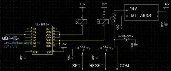 OA47 |
||||
Grogster Admin Group Joined: 31/12/2012 Location: New ZealandPosts: 9986 |
These modules do have a habit of burning out the chip if they are adjusted incorrectly. Page two of the PDF for this boost-converter chip, states that the voltage on the FB pin(3) is 6v absolute maximum. Many of the modules from eBay etc don't use the correct potential-divider arrangement, and if the multi-turn trimmer is set so it favours the supply-rail end of the travel, you will EASILY apply more then 6v to the FB pin, and then the device has an internal breakdown and catastrophic failure of the device then follows. These modules seem to use the basic circuit on page one of the PDF, but they have replaced R1 - which is a set value in the basic circuit - with a variable resistor - the blue multi-turn trimmer. What this allows to happen, is that the potential applied to pin three, can EASILY be set to more then 6v with respect to ground, and then the chip will fail - usually by way of burning itself into silicon heaven. I have attached the PDF in case you don't have it. 2019-05-09_083259_MT3608_Step-Up_converter.pdf The best way to adjust these units, is to NOT apply more then 6v at initial adjustment, that way, there is no way for pin three to rise above 6v. I would use 5v or so. Then you adjust your output voltage. When fed with LESS then 6v, they work just fine. I don't recommend using these modules above 5v with the arrangement of the circuit used on these modules. They certainly CAN run from an input voltage up to 26v, but you have to be sure that the potential on the FB pin is LESS then 6v, and the simple divider used on these modules does NOT prevent that - so the modules self-destruct when you exceed that maximum. Smoke makes things work. When the smoke gets out, it stops! |
||||
| OA47 Guru Joined: 11/04/2012 Location: AustraliaPosts: 1050 |
Here is a pic of the solenoids I have to control. 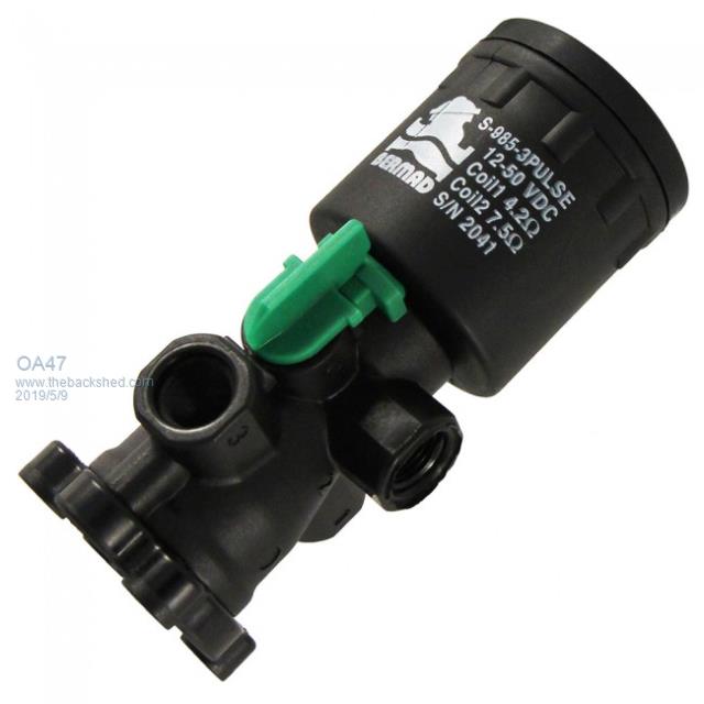 I thought originally that I could use these LM2596 units but it seems they cannot boost voltage. 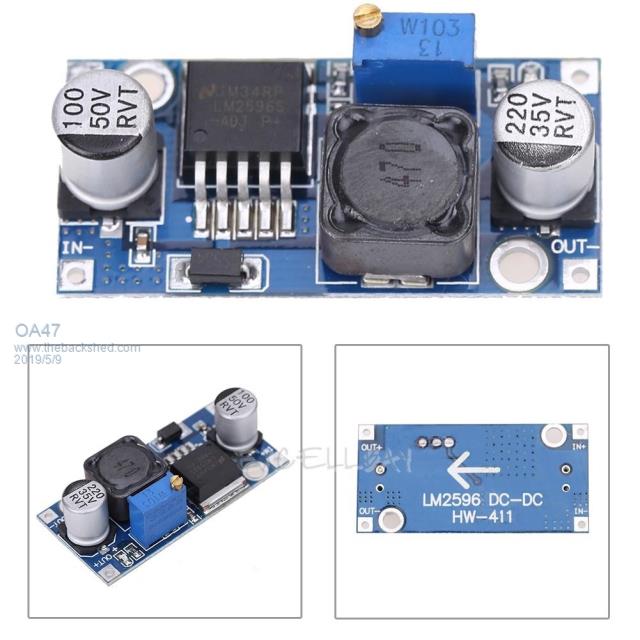 @Grogs your post is giving me the feeling that the MT-3608 module is not a wise choice. OA47 |
||||
| Grogster Admin Group Joined: 31/12/2012 Location: New ZealandPosts: 9986 |
I've used lots of those LM2596 modules, and they work well, but are a buck-converter, and the input voltage has to be larger then the wanted output - pretty much like any standard linear regulator. No, they cannot boost. The 3608 module is really only good for boosting when the input voltage is 5v or less. It is because of the way the module has the trimpot arranged, which can easily allow for over-voltage on the FB pin. Here is a schematic of the module: 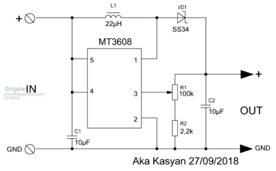 As you can see, they have made the multi-turn trimmer R1, and the issue you have with this arrangement, is that if you apply - say - 12v to the input, and the trimmer is up near the positive output end of it's travel, when you switch on the juice, the supply voltage flows into the trimmer via the 22uH inductor and the Schottky diode. with the wiper of the trimmer up too far towards the positive end, this puts a potential of much more then 6v on the FB pin, and the device catastrophically fails due to breakdown of the FB pin input. The FB input is probably nothing much more then a gate junction internally, and just like any other MOSFET gate, if you exceed the maximum gate voltage.....Bang!  With a different schematic layout, this chip would work fine with higher input voltages, but the way they have designed the module, if your input voltage is more then 6v, and you turn the trimmer up too far, it is fatal for the device. The design needs refinement for use as an adjustable boost converter, as it is not very foolproof the way they have made them.  The datasheet gives the formula to calculate the output voltage from R1 and R2, but they are expecting you to use set resistors for R1 and R2, NOT an adjustable resistor for R1 - that is where the design falls over a little.  They are only for low-power use. Less then 1A, really. Although they are rated for 2A, I tend to de-rate things like this UNLESS you can guarantee the source of the parts that they have used, and as you can't..... Smoke makes things work. When the smoke gets out, it stops! |
||||
| robert.rozee Guru Joined: 31/12/2012 Location: New ZealandPosts: 2541 |
the LM2596 is a buck (step-down) regulator: http://www.ti.com/lit/gpn/lm2596 the LM2577 is a boost (step-up) regulator: http://www.ti.com/lit/gpn/lm2577 with a bit of trickery one can be persuaded to act as the other, or to even act as a buck-boost regulator, but the result is usually suboptimal. it looks like you are driving a water valve, with two separate coils - one to turn on the valve, the other to turn it off. just had a look at the datasheet for a IR-S-985-3W, which i presume is very similar. i'd be using the full 50v (or as close as possible), as the energy stored in a capacitor is (C x V^2) / 2 where C is the capacity in farads. so going from 18v to 36v gives you four times the stored energy, going from 18v to 50v gives you nearly eight times the stored energy. the absolute maximum switching current of the LM2577 is 6 amps. assumung 12v input supply, this translates to 1.5 amps output at 48v (actually a bit less current due to the efficiency). so we can get away with a 47 ohm limiting resistor feeding the capacitor. as an aside, i'd not want to be drawing this current for any length of time without any heatsink on the regulator, so make sure you don't leave either relay closed for more than a second. charge time to achieve about 65% of the supply voltage is R x C. lets say a 50v supply, a 47 ohm resistor, and a 4700uF capacitor. this gives: 50 x 4700 x 10^-6 = 0.24 seconds. so to charge the 4700uF capacitor to close to the full 50v is going to be a few seconds at most. i presume this fits in with your planned operation? the datasheet for the valve i've looked at doesn't give any information on cycle times or maximum lifetime cycles for the device. but at a guess, i'd say it is likely to be around the 20,000 actuations mark. cheers, rob :-) |
||||
| OA47 Guru Joined: 11/04/2012 Location: AustraliaPosts: 1050 |
Thanks all for all the valuable help. I have ordered some LM2577 units but until they arrive I will try out the ones I have at 5V input and see what happens. OA47 |
||||
| The Back Shed's forum code is written, and hosted, in Australia. | © JAQ Software 2026 |
