Notice. New forum software under development. It's going to miss a few functions and look a bit ugly for a while, but I'm working on it full time now as the old forum was too unstable. Couple days, all good. If you notice any issues, please contact me.
poida Guru Joined: 02/02/2017 Location: AustraliaPosts: 1388
Posted: 09:19pm 26 Oct 2021
Copy link to clipboard
Print this post
At work today so the test inverter task must wait.
As soon as inverter is commanded to stop, during the next control loop (at 50 Hz) PID will not execute any more Now it's simple ramp down to zero power from whatever power level it was when commanded to stop. Again, feedback voltage is ignored during this mode of operation.wronger than a phone book full of wrong phone numbers
wiseguy Guru Joined: 21/06/2018 Location: AustraliaPosts: 995
Posted: 06:53am 29 Oct 2021
Copy link to clipboard
Print this post
I decided to critically look at the current waveforms to the primary of the toroidal and to investigate what effect the value of AC capacitance has on the waveforms. I don't intend to post all the CRO shots I've taken yet as I'm not sure they are representative of what a good inverter looks like. I would like to post all the information and pics but first I need to make sure it is 100% relevant or else it is really just pollution.
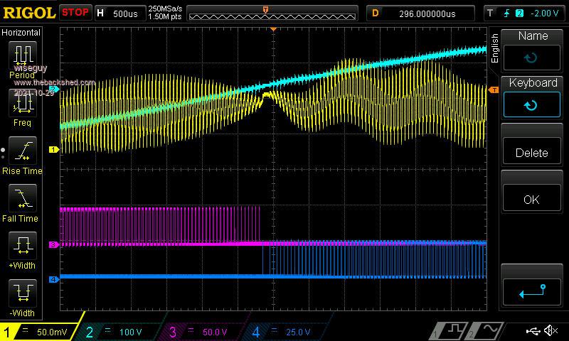
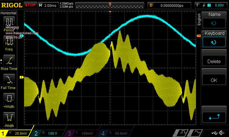
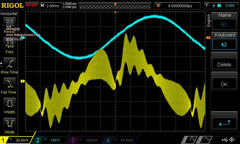
During my testing I found the following waveforms at the output of the H bridge, Purple and dark Blue.
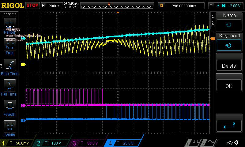
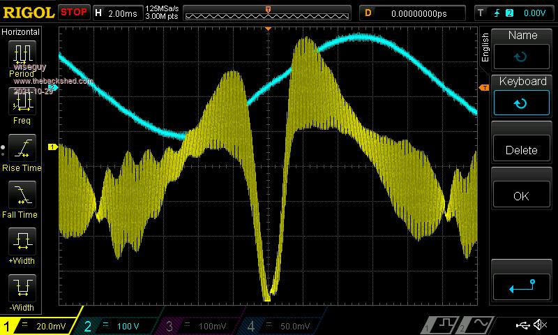
The Yellow trace is primary current at 0.5A/Div. The light Blue is mainsV 100V/div. The first 2 images are at 19.2kHz at the zero cross & the second pic is expanded
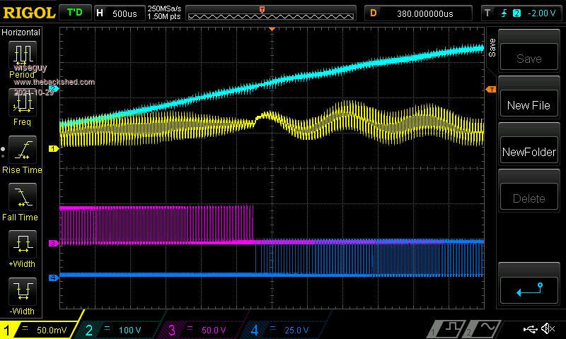
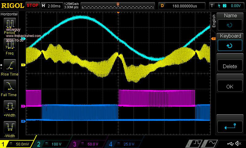
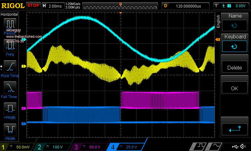
The next 2 images are at 25kHz at the zero cross & the second pic is expanded
In all the images you can see a solo blue pwm before a pause and then normal blue pwm. I believe that this solo pulse belongs to the purple trace and it changed to the opposite drive one cycle early.
At 19.2kHz the second to last purple pulse visible is 2.4uS the last purple pulse is 1.6uS, there is no 0.8uS purple pulse.
But where I would have expected the 0.8uS purple pulse, there is a 0.8uS Blue pulse then a pause (where I believe the true zero cross should be) then another 0.8 Blue pulse (which I believe should be the first real Blue drive pulse ) then a 1.6uS Blue pulse then a 2.4uS Blue pulse etc.
I am convinced that the solo first 0.8 Blue pulse before the pause is actually supposed to be the last purple pulse, then it would all make sense.
If the address counter to the array was out by one it could have this effect. I admit to being software challenged but I believe that OCR1A and OCR1B changed state one address too early. As if the counter is 0-255 instead of 1-256 or a >than in lieu of >than or = to or other similar trifling error.
Whether this little glitch actually affects the ringing seen after the zero cross or affects a slight offset in the flux can only be determined after it is fixed and then I can compare the two results.
Edit: Poida, I am having a senior moment - all this felt a bit like dejavu so I did some searching and apparently I have rediscovered the same effect almost 2 years to the day later. (and come to the same conlcusion). You told me then that the problem was unfixable - if this is still your position and it is unfixable I will just dust myself off and get on with it & accept it as it is. Edited 2021-10-29 17:28 by wiseguyIf at first you dont succeed, I suggest you avoid sky diving.... Cheers Mike
wiseguy Guru Joined: 21/06/2018 Location: AustraliaPosts: 995
Posted: 01:52pm 29 Oct 2021
Copy link to clipboard
Print this post
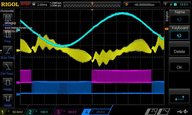
Tony, you asked if I have captured any CRO traces when the grunt occurs.
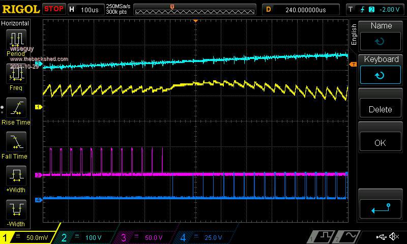
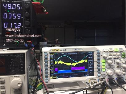
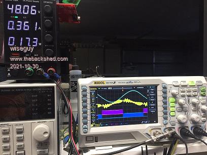
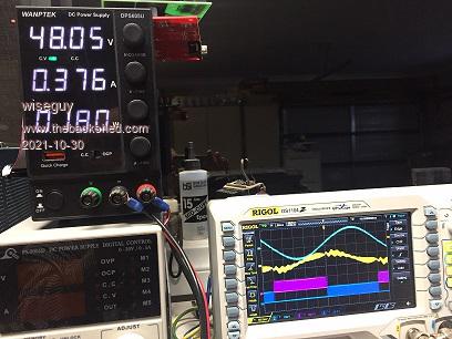
Now that I have the current probe on the transformer primary here are 3 traces one when idling normally, second beginning of grunt, third near max of grunt.
Normal Idle
Start of grunt
Max grunt
Light blue is Vmains ~100V/div Yellow is primary current 2A/div.If at first you dont succeed, I suggest you avoid sky diving.... Cheers Mike
Warpspeed Guru Joined: 09/08/2007 Location: AustraliaPosts: 4406
Posted: 09:57pm 29 Oct 2021
Copy link to clipboard
Print this post
Oh golly !!! That is quite dramatic.
What might be causing it I have absolutely no idea.
The first thing I would do is try using a different transformer. Even something smaller, and maybe a different choke too. If the grunt stays the same, it must be related to corruption of the driver waveform somehow. If it changes character or goes away completely, its more likely to be a magnetics related problem.Cheers, ĀTony.
poida Guru Joined: 02/02/2017 Location: AustraliaPosts: 1388
Posted: 10:08pm 29 Oct 2021
Copy link to clipboard
Print this post
yes, we have examined this before. Was it 2 years ago? And yes, it is unfixable, and insignificant.
I am very pleased you have obtained great captures from the DSO showing what is happening.
The gold is in the last screen of the second post, showing clearly the current peak that appears during the grunt sound.
It would be very productive if you could find another transformer and do the same tests with it in place of the toroid.
Also, you could do some tests with a bit of DC trim (0, +1, +2 etc) noting the size of the current pulse dip. If it gets bigger then go 0 -1, -2 etc In all cases I could reduce the grunt to near zero with +/- 1 trim with the two toroids I use in testing.wronger than a phone book full of wrong phone numbers
Solar Mike Guru Joined: 08/02/2015 Location: New ZealandPosts: 1123
Posted: 11:18pm 29 Oct 2021
Copy link to clipboard
Print this post
Seems weird that the anomaly is occurring in one segment of the sine curve and not the other; what happens if you swap the transformer primary cables over.
Cheers Mike
wiseguy Guru Joined: 21/06/2018 Location: AustraliaPosts: 995
Posted: 12:20am 30 Oct 2021
Copy link to clipboard
Print this post
I have 2 x transformers in parallel, both rated at around ~2.5kW. There are a few choices, I can totally reverse 1, or the other or reverse both. All equally unpalatable - there is a big disadvantage to a very compact inverter where the transformers and choke are under a plate mounted above them that has all the smarts and wiring above the plate which all has to be dismantled to make any such changes.
As I see it if the table has 200 entries we are getting 199 on one half sine and 201 on the other half - it is not 1 bit different its actually 2 bits differential and one of the bits goes in the wrong direction before the zero cross. My engineering perfectionist approach wont let me live with it so I will probably get our new software whiz kid at work to see if there is a different solution.
Perfection (or striving for it) definitely has a negative side to it, but there is also a positive - I wont wonder whether it might have made a difference or improve the ringing or saturation.
I have a piece of humble pie standing by so when Poida says "I told you it wouldn't make any bloody difference" I can eat away heartily ! Edited 2021-10-30 10:47 by wiseguyIf at first you dont succeed, I suggest you avoid sky diving.... Cheers Mike
Solar Mike Guru Joined: 08/02/2015 Location: New ZealandPosts: 1123
Posted: 12:49am 30 Oct 2021
Copy link to clipboard
Print this post
Having a compact assembly does make it difficult for ad hoc changes; if you can, place an additional choke in series to increase the inductance a little, see what that does.
Cheers Mike
Warpspeed Guru Joined: 09/08/2007 Location: AustraliaPosts: 4406
Posted: 12:56am 30 Oct 2021
Copy link to clipboard
Print this post
You don't have to physically remove the old transformer, just "hot wire" something else to the mosfet bridge.Cheers, ĀTony.
wiseguy Guru Joined: 21/06/2018 Location: AustraliaPosts: 995
Posted: 02:03am 30 Oct 2021
Copy link to clipboard
Print this post
I want to clarify a couple of things. I am grateful to Poida and the ongoing support help and encouragement from him. The concept of getting the "whiz kid" to look at the software is a longer term approach, if he really is that clever he might decline the "offer" - I am quite happy to exploit & use what I have in the meantime.
I will be reporting back on the 20/25/40/50kHz options that Poida created, to see what a difference it makes in terms of Idling and medium load efficiency etc.
I also collected traces from the inverse (other zero cross) and the exact sequence is the same but swapped between dark blue and purple. So there is not a 2 bit differential between each half sine. It is more like the table did not read from 0-200 for each half but rather from -1 to 199 for each half - the halfs might have some slight distortion but the energy content should be balanced.If at first you dont succeed, I suggest you avoid sky diving.... Cheers Mike
InPhase Senior Member Joined: 15/12/2020 Location: United StatesPosts: 178
Posted: 02:25am 30 Oct 2021
Copy link to clipboard
Print this post
Silly question maybe, but I have had some faulty Chinese Nanos in the past. Have you tried a different Nano?
wiseguy Guru Joined: 21/06/2018 Location: AustraliaPosts: 995
Posted: 02:38am 30 Oct 2021
Copy link to clipboard
Print this post
Sometimes the silly question is the one that is not asked.
I have been using 2 quite different nano's, one has the earlier old style bootloader. I'm comfortable that they are blameless but sometime soon I will solder the extra bits to a third type I recently bought and test it, to be sure to be sure!If at first you dont succeed, I suggest you avoid sky diving.... Cheers Mike
wiseguy Guru Joined: 21/06/2018 Location: AustraliaPosts: 995
Posted: 03:11am 30 Oct 2021
Copy link to clipboard
Print this post
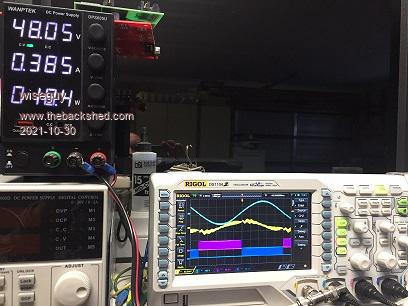
The results in my inverter of the + & - 1 trims are shown below. In both cases the idle current went from 18W to ~ 21W and whilst the grunt was slightly quieter with the +1 version the idling hum had a more metallic buzz in both cases. I wont be trying any trims greater - the results can be well predicted.
-1 phase trim
+1 phase trim
Next I will try the different 25/40/50kHz versions but in a couple of hours, first I need to fix a friends microwave oven............
I wish I had a friend that would come around and fix up my stuff when it stops. Edited 2021-10-30 14:26 by wiseguyIf at first you dont succeed, I suggest you avoid sky diving.... Cheers Mike
poida Guru Joined: 02/02/2017 Location: AustraliaPosts: 1388
Posted: 05:32am 30 Oct 2021
Copy link to clipboard
Print this post
I did this with the 3kW toroid that had been exposed to some big events and has this same issue. The peak then appeared on the other 1/2 cycle and the peak was inverted.
This showed me it's not the inverter board, it's the toroid.wronger than a phone book full of wrong phone numbers
poida Guru Joined: 02/02/2017 Location: AustraliaPosts: 1388
Posted: 05:46am 30 Oct 2021
Copy link to clipboard
Print this post
WG: good to see these results with the trims. Did you notice the current pulse alter with the changes? Less in size? Different polarity?
Even a trim of 1 adds a significant DC bias to the primary which brings one or the other 1/2 cycles further into saturation compared with the other.
The primary winding/choke/FETs total DC resistance in my test inverter is probably a lot higher than your build. This contributes to less DC bias build-up
I bet your build is quite low resistance and that means DC bias will take longer than mine to dissipate as heat/sound.
For instance the current test setup uses a single HY4008 per leg on the power board. The DC resistance of the choke + primary is (5.84 Amps, 0.310V across it means) 53 mOhom
What is your builds primary circuit resistance?wronger than a phone book full of wrong phone numbers
wiseguy Guru Joined: 21/06/2018 Location: AustraliaPosts: 995
Posted: 07:17am 30 Oct 2021
Copy link to clipboard
Print this post
At 2A I measured 21.1mV one way and 21.9mV with the probes reversed so if we use the mean of 21.5 that equals the equivalent of 10.75mOhms.
The results of the inverter at idle for the 20, 25, 40 and 50kHz were very similar.
20kHz
25kHz
40kHz
50kHz
In all my recent tests I use the startup time as 500, the grunt is still there but at about half the severity.
Interesting though at 40 & 50kHz the grunt is about 20% of what it was and disappears very quickly.
Now I need to hook up a 48V power supply with (edit grunt NO) many amps capability and check the efficiencies of these 4 different PWM frequencies at 1kw and 2kw an idle test is a bit meaningless. Edited 2021-10-30 18:02 by wiseguyIf at first you dont succeed, I suggest you avoid sky diving.... Cheers Mike
wiseguy Guru Joined: 21/06/2018 Location: AustraliaPosts: 995
Posted: 08:53am 30 Oct 2021
Copy link to clipboard
Print this post
Ok now for the next instalment, using a 1.2/2.4 kW fan heater as a load. I hooked up 2 x Elteks capability of ~80 Amps for the next tests. Voltage was 53.1VDC
Result 1) 20kHz at 1.2kW 21.7A at 2.4 kW 44.3A Result 2) 25kHz at 1.2kW 21.7A at 2.4 kW 44.3A Result 3) 40kHz at 1.2kW 21.7A at 2.4 kW 44.3A Result 4) 50kHz at 1.2kW 21.7A at 2.4 kW 40.2A
These figures look fudged but they are what happened - I waited for a few minutes each time to get the elements at normal operating temperature as the current was initially higher & falling but eventually settled. Edit: Ok I admit the time could be classified as fudged - I did not measure time accurately, but after the current was quite stable at 44.3A I switched to the 1.2kW setting and noted the 21.7A which was also stable at the time of measurement, perhaps if I had waited for the same exact times for each, there might have been a 0.1A or so variation.
The results of no 4 at 50kHz did not surprise me in the least. The output mains voltage drooped/dropped by ~ 5V that is why the current fell for the same resistive load. The mains was quite steady at ~ 233.5 +/- 0.1 for all other measurements
The series choke energy storage capability is reducing each time the frequency is increased. I am surprised it did not show up at 40kHz - there may not have been much headroom at 40kHz above 2.4kW.
For optimum performance the chokes should be engineered whether by calculation or/and empirical testing to suit whatever frequency is chosen. Note, the choke for 50kHz will be much smaller units than at 20kHz also with less turns. It does prove the platform I designed is performing very well and I think there is still scope for higher PWM frequencies yet. The fast switching capability of the opto buffered drivers to the FETs show no degradation even at 50kHz except less than a watt extra idling current.
I believe with the right chokes, my inverter would perform at 50kHz as well as it did at 20kHz including with momentary high current loads such as my compressor.
Any way the microwave I fixed was an inverter unit so a small consolation, it just needed a new globe so you could see what kind of mess you were making internally whilst cooking. Now I feel all invertered out and will take a break from all the fun. - I admit I did wince each time I hit the run switch at the higher Freq and wattage loads what a wimp...
There is one last test to run, although painful to do I will swap the bridge to transformer primary/choke connections to see probably a high going grunt ?? Edited 2021-10-31 08:53 by wiseguyIf at first you dont succeed, I suggest you avoid sky diving.... Cheers Mike
wiseguy Guru Joined: 21/06/2018 Location: AustraliaPosts: 995
Posted: 06:17am 31 Oct 2021
Copy link to clipboard
Print this post
OK I reversed the primary and started up from cold as the grunt started I hit stop on the CRO and captured what was happening.
The Current probe remained on the same bridge output point and the primaries were swapped after that point. Triggering on the CRO remained the same.
First the trace before the swap.
And now with the primary reversed.
I have to say the results really surprised me.
The tendency to saturation stayed exactly where it was, a negative going excursion on the positive drive peak. The difference in yellow amplitude for both pictures is due to the different CRO settings of 20/50 mV/Div (0.2A vs 0.5A).
I cant really make sense of the current probe display reading in either picture and I wonder if it may be reversed in both pictures. Whether they are both right or both wrong the results show that we got essentially the same image with the primary reversed.
Note I triggered on the mains output (light blue trace) so the yellow current trace with the grunt factor is now showing 180 degrees out. Edited 2021-10-31 16:19 by wiseguyIf at first you dont succeed, I suggest you avoid sky diving.... Cheers Mike
wiseguy Guru Joined: 21/06/2018 Location: AustraliaPosts: 995
Posted: 08:53am 31 Oct 2021
Copy link to clipboard
Print this post
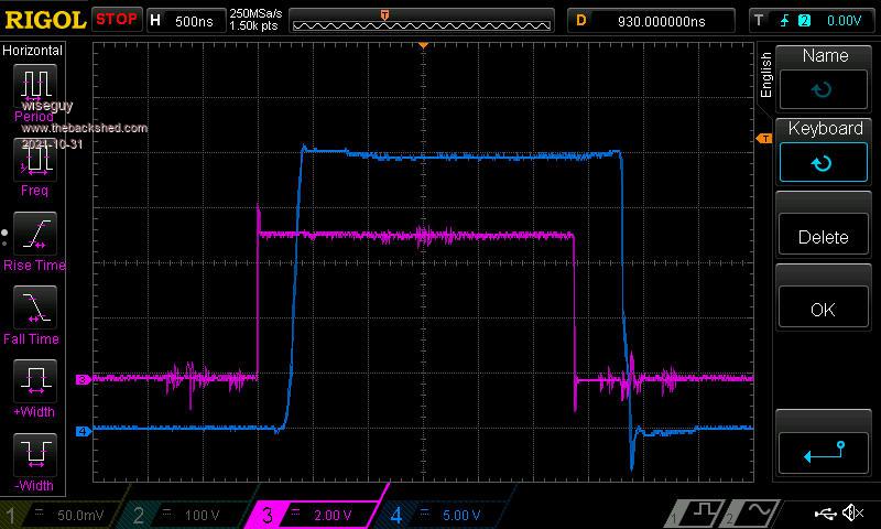
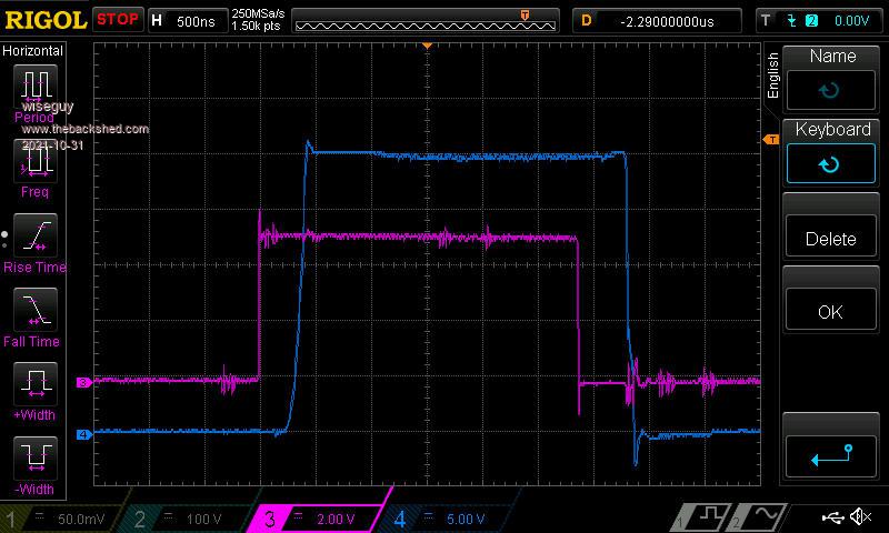
I decided to check the integrity of the signal from the D9 & D10 H bridge drives of the Nano to the actual Mosfet to choke/transformer outputs, the results are below.
The D10 output from the nano compared to the H bridge output.
The D9 output from the nano compared to the H bridge output.
Both the purple traces are near as dammit 2.85uSecs. The D9 & D10 blue traces are closer to 2.9uSecs
Are they balanced - I look forward to opinions - I don't want to comment yet so as not to influence others opinions.
I am now wondering if say a 25nSec difference cumulative error on for instance the LHS drive added over a complete start from cold could cause the grunt.
Maybe by not letting it soft stop and restarting it adds less of the 25nSec error so no grunt on an interrupted soft stop ==> restart ??
I am thinking of swapping the high side optos from left to right next to see if it changes anything. If not I'll put them back to normal and try the low side optos.
I hope this is not boring people sh.tless, but it is a true record of my exploits in trying to identify something whose cause is proving to be a mite elusive and may help in making inverters more balanced (robust?) if solved, or at the least explaining the cause of grunts.
Edit: I might also take this opportunity of asking our resident walking data book alias SolarMike if you are aware of a pin for pin replacement for the FOD3182, that has much tighter specs for matching rise and fall times and will operate down to ~ 8 - 10V supply? It might save me some time - hopefully they are available on less than a 55 week lead time and I can afford 4 off. I'm wondering if the SI8261BBC you suggested to Inphase might be one good candidate ?? Edited 2021-10-31 19:28 by wiseguyIf at first you dont succeed, I suggest you avoid sky diving.... Cheers Mike
Warpspeed Guru Joined: 09/08/2007 Location: AustraliaPosts: 4406
Posted: 09:33am 31 Oct 2021
Copy link to clipboard
Print this post
O/k, next thing I would try is disconnecting the transformer altogether. Try connecting a resistor and capacitor to form an integrator to each side of the bridge.
That should produce two nice sine clean waves without any magnetics to screw things up. See if that grunts.....Cheers, ĀTony.