Notice. New forum software under development. It's going to miss a few functions and look a bit ugly for a while, but I'm working on it full time now as the old forum was too unstable. Couple days, all good. If you notice any issues, please contact me.
mackoffgrid Guru Joined: 13/03/2017 Location: AustraliaPosts: 460
Posted: 05:53am 08 Nov 2019
Copy link to clipboard
Print this post
I'm sure you'll sort it out. I may be useful just to have two versions of the software, with and without feedback.
BTW, is the feedback being locked only once per cycle?
Good Going, Cheers
Andrew
wiseguy Guru Joined: 21/06/2018 Location: AustraliaPosts: 991
Posted: 06:25am 08 Nov 2019
Copy link to clipboard
Print this post
Andrew, rather than lead you astray I direct you to the first page of "Poidas inverter software control topic" where Peter does a good job of describing what the software is up to.
I believe that the code I am using from Poida though applies a correction once per 360 degrees.If at first you dont succeed, I suggest you avoid sky diving.... Cheers Mike
Warpspeed Guru Joined: 09/08/2007 Location: AustraliaPosts: 4406
Posted: 06:40am 08 Nov 2019
Copy link to clipboard
Print this post
Wiseguy,
The flux in the transformer core swings sinusoidally as you would expect. ĀBut realise that the voltage this produces in both primary and secondary will reach their peaks in one direction during the fastest rate of flux change. The flux is ninety degrees out of phase with both the primary and secondary voltages.
So when the flux saturates in one direction, its the zero crossing point that goes all wonky, but only in one direction.
It then starts to draw larger peak currents as it approaches saturation, and that effectively creates some larger ohmic voltage drops in both the primary wire, and whatever series impedance powers the primary.
That reduction in voltage over one half cycle tends to cancel out the original unbalance in volt/microseconds. Ā So it does not ramp up all the way into hard saturation, and then blow up. It will just work over a region of flux swing that is offset in one direction if the original volt/microsecond unbalance is fairly small.
Yes overall corrective voltage feedback would certainly be possible, and it could be brought in fairly gradually. But once you have a working voltage feed forward system, I think you might be rather surprised how well it works without anything else. Edited 2019-11-08 16:46 by WarpspeedCheers, ĀTony.
wiseguy Guru Joined: 21/06/2018 Location: AustraliaPosts: 991
Posted: 05:57am 15 Nov 2019
Copy link to clipboard
Print this post
Tony I have tried to tune my transformer but it doesnt feel right. I used a function generator in series with a 4k7 resistor and connected the secondary (240V) with no cap initially.
The natural resonance is around 4kHz and quite broad. Using 2 x 0.68uF caps it resonates to a sharp peak at around 74Hz. Using 3 x 0,68uF caps it resonates at ~ 59Hz.
I thought normally caps of 2 - 5uF were usually required - but I have no experience tuning toroid secondaries - does the above seem right to you ?
I havent done a couple of resonance/primary inductance calcs to confirm yet - have to go out now, will check this later, but interested in your comments so far. Edited 2019-11-15 16:52 by wiseguyIf at first you dont succeed, I suggest you avoid sky diving.... Cheers Mike
Warpspeed Guru Joined: 09/08/2007 Location: AustraliaPosts: 4406
Posted: 07:52am 15 Nov 2019
Copy link to clipboard
Print this post
Yes, normal natural resonance in the low Khz region is pretty typical, and it will be a broad low lossy hump. Eddy current losses in the core will be quite high at those frequencies and an exact peak can be difficult to find. As you tune it much lower down in frequency, the peaking becomes much sharper and a lot more distinct.
Mark was around here a few weeks back with the toroid for his new camper van inverter.
That used a single fairly skinny toroid as it was only for a 2.5Kw inverter, and from memory the number of secondary turns ended up being quite high at something around 320 turns going around the toroid twice with two full layers.
Anyhow, we ended up requiring some ridiculously small amount of capacitance for tuning, 1uF plus an 0.47uF in parallel ended up at 74Hz as I remember.
That is pretty much where you are, so its quite possible.
That inverter worked spectacularly well very first attempt without a single problem.Cheers, ĀTony.
renewableMark Guru Joined: 09/12/2017 Location: AustraliaPosts: 1678
Posted: 09:37am 15 Nov 2019
Copy link to clipboard
Print this post
Yeah, even the wife couldn't break it.Cheers Caveman Mark Off grid eastern Melb
wiseguy Guru Joined: 21/06/2018 Location: AustraliaPosts: 991
Posted: 03:37am 16 Nov 2019
Copy link to clipboard
Print this post
Thanks Tony I knew my method was ok just wasnt sure of the values to expect.
This will be a rather longish post with corresponding pictures that describe my inverter performance during the tests so far.
To recap, my inverters output configuration is 4 x HY4008 Fets per leg of the bridge. The power stage FET gates derive power from isolated gate power supplies and the lower 2 legs have a -5V Gate voltage when the FETs are off. The power stage optos are driven from a nano on a PCb controller of my own design. The software used is the Variac code with no feedback loop.
The Toroidal tranny is ~3kW, the choke I am using is just 3 x HighFlux ring cores (no iron).
I have also wanted to see the differences between tuning the affair for 50Hz & 75 Hz to find out what it all means. To this end I made a capacitor bank that I could easily switch out the capacitors that tuned it for either 50 or 75Hz.
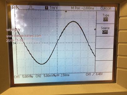
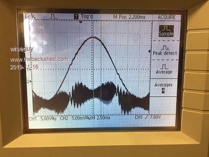
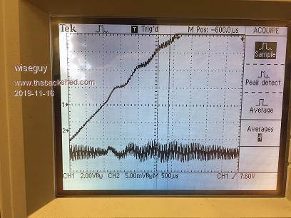
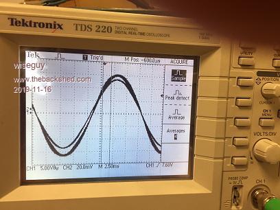
We start with a sinewave with no load at the idle - note the small distortions.
Using the current probe there is a resonance that you can see superimposed on the sine wave during the first 90 degrees and at 180 - 270 degrees just after the zero crossings.
Using the cursors the resonance measures at around 1.5 to 1.6kHz also note the symmetry as the resonance starts at roughly the centre of the previous hash.
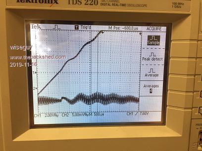
Now note the symmetry is upset a bit and this is accompanied by a change in the transformer noise - a small buzz is present and wanders in volume as the symmetry moves from balanced to unbalanced input current also increases a bit (5%) with the increaed noise.
I want to emphasise here that the imbalance wandering is random and can sit for long periods in balance and can for no apparent reason tend towards unbalance with various degrees of shift. I suspect that occasionally this might get much worse and it appears to rely on randomness stacking up. I surmise that the nano/code might be operating at the limitations of its performance re timing etc.
Next I used a fan heater as a load with just the fan on (25W).
Next few pics with a 1kW load
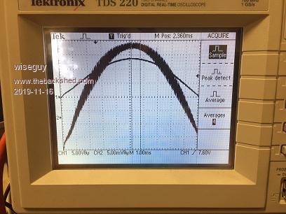
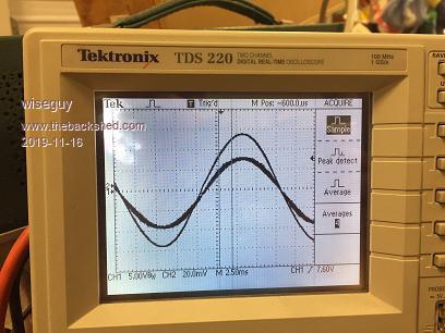
Now we zoom in on the voltage and current peak (transformer tuned to 50Hz.
At this point I changed the transformer tuning to 75Hz note the current phase moves slightly to the right and it draws a small amount of extra current.
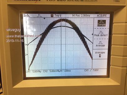
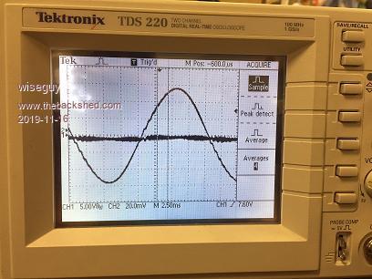
Next we unload the inverter and look at the sinewave distortion tuned to 75Hz
This shot is the sinewave distortion (a bit lower) when tuned to 50Hz
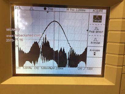
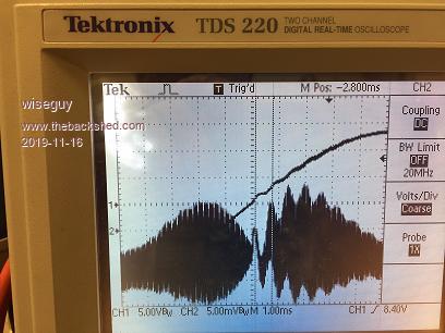
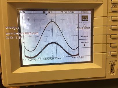
Lastly 3 pictures showing current and voltage waveforms scaled for comparisons First at 25W
Now at 1kW
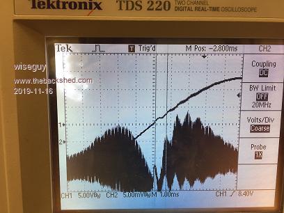
Now at 2kW
During testing with extended periods of 1kW the temperature of the heatsink rose from 19.7 to 20.3 degrees, the aluminium bar the FETs are on rose to 20.8. The choke also measured 20.8 degrees the toroid rose to 24.4 degrees, the Eltek power supply (48V) powering the affair rose to 33.3 degrees.
With regard to transformer tuning in my setup I cannot see any degradation or penalty in tuning the transformer for 50Hz. I actually see a very small improvement in doing so, slightly less current idling and under load, and slightly less distortion of the 1.5kHz resonance.
I am not advocating that anyone changes their current setup or transformer tuning. My comments and findings are on my setup and how it appears to be performing.
My earlier efficiency figures were slightly generous (a percent or 2)in favour of higher efficiency.
I will report more accurate efficiency figures in due course. I will also scope (carefully!) the gate drive waveforms and other such things during operation.
Soon I will also couple 2 Elteks in parallel and drive it to 4kW to see what happens. Then we will give it the drop saw and compressor tests.
Lastly the 1.5 kHz current resonances seem to be artefacts of the nano output drive pulse trains. It is interesting to note that they cause distortion after the zero crossings when the voltage is rising from zero but are almost invisible at the same point 90 degrees on when approaching the zero cross.
These small resonances are not really a problem to performance or efficiency, more of a curiosity. The more worrying part is really the flux which appears to wander back and forth a bit randomly to a random degree of effect. I have no idea if given enough time it could cause a serious saturation event when enough randoms stack up in one direction.
Maybe this would/could never occur to this degree ?If at first you dont succeed, I suggest you avoid sky diving.... Cheers Mike
Warpspeed Guru Joined: 09/08/2007 Location: AustraliaPosts: 4406
Posted: 04:14am 16 Nov 2019
Copy link to clipboard
Print this post
What is the design flux density of your transformer ?Cheers, ĀTony.
wiseguy Guru Joined: 21/06/2018 Location: AustraliaPosts: 991
Posted: 06:26am 16 Nov 2019
Copy link to clipboard
Print this post
The short and flippant answer is - I have no idea I never designed it I just used it.
It is hard to tell whats under all the windings in terms of core cross section, but I guess I could make some estimates.
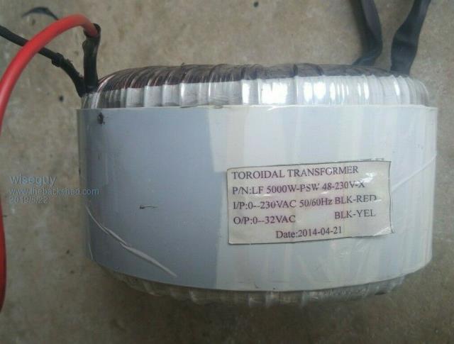
This is what was written on the transformer.
I know at 240V its idling current was 40mA and true power ~ 6.5W I know at 250V its idling current was 50mA and true power ~ 7.3W
Not sure why you asked the question and what you are leading to ?
Perhaps this is also the right time to clarify that the Eltek currently puts out 53.2V as it is trying to boost charge a battery that doesnt exist - I need to finish making the Eltek controller and have a true variable voltage variable current source.
I also know that I will need to reduce the primary turns or else I will have to be happy with ~ 215V for 45V in - which I couldnt accept. Currently for 48V in I would get about 230V out. The turns ratio is ~ 6.7:1 - I know it needs to be closer to 8:1.
It is still early days and I admit I was a bit impatient to run some preliminary tests.
Do you think the series choke could be playing a part in those 1.5kHz resonances ? Edited 2019-11-16 16:48 by wiseguyIf at first you dont succeed, I suggest you avoid sky diving.... Cheers Mike
Warpspeed Guru Joined: 09/08/2007 Location: AustraliaPosts: 4406
Posted: 06:54am 16 Nov 2019
Copy link to clipboard
Print this post
The idling power is quite low, and the value of tuning capacitors required suggests a fairly high inductance. So it looks like there are plenty of turns, and maybe (?) a fairly low flux density.
Most commercial transformers run a pretty high flux density so they can get away with minimal iron and copper. That can cause problems with high inrush at initial power up, and in an inverter high idling current, and unfortunately pretty easy saturation.
If it is saturating, could still be the transformer, or the drive waveforms are not symmetrical between positive and negative half cycles.
Try running the inverter at much reduced voltage, say 30v dc and see if the anomaly persists.Cheers, ĀTony.
wiseguy Guru Joined: 21/06/2018 Location: AustraliaPosts: 991
Posted: 07:09am 16 Nov 2019
Copy link to clipboard
Print this post
I agree I think it was wound to minimise magnetising current.
When I start to play with the primary turns I will also put 10 turns on and see what voltage it yields. That will also help in determining how many turns to remove. It should also give us an idea of the flux density with some rough figures for core xsection.
The 1.5kHz might be related to the series choke I guess - maybe its not related to the nano outputs ? However the wandering of the symmetry at zero cross I feel is nano related. The 1.5kHz and flux wander just look related - they may be quite unrelated.
More testing required to try to get to the bottom of the 1.5kHz ripple cause.If at first you dont succeed, I suggest you avoid sky diving.... Cheers Mike
Warpspeed Guru Joined: 09/08/2007 Location: AustraliaPosts: 4406
Posted: 07:48am 16 Nov 2019
Copy link to clipboard
Print this post
The choke and the primary will have their own quite separate resonances. How the whole thing behaves depends on what frequencies are present coming out of the pwm switching process.
There will be a lot of energy at 50Hz (obviously) and any harmonic distortion will create some fairly strong energy at multiples of 50Hz. Then there will be a lot of energy again at 23Khz, and harmonics of that too, which should not be so much of a problem.
There is not a lot that can be done about these resonances. They are always going to be there, but it is possible to move them around to a certain extent if a particular resonance turns out to be a nuisance.Cheers, ĀTony.
Warpspeed Guru Joined: 09/08/2007 Location: AustraliaPosts: 4406
Posted: 08:13am 16 Nov 2019
Copy link to clipboard
Print this post
Just had a thought.
That 1.5uF across the secondary will be reflected back into the primary as turns ratio squared, or about 1.5 x 6.7 x 6.7 = 67.3uF.
That will form a series resonant circuit with the inductance of the choke, which often ends up at around 1.5Khz, which is the ideal place for it.
If your choke just happens to be 167uH that is where your 1.5Khz is coming from for sure.
Now 1.5 Khz is thirty times 50Hz. And 1.5KHz is one fifteenth of 23Khz.
So its a long way away from either frequency where there is a lot of disturbing energy, which is a good place for it.
Note that this is going to be a very low impedance series resonant circuit. Huge current can flow, and its directly across the switching bridge. So its important that there is minimal energy where this phantom resonance occurs.Cheers, ĀTony.
wiseguy Guru Joined: 21/06/2018 Location: AustraliaPosts: 991
Posted: 12:01pm 16 Nov 2019
Copy link to clipboard
Print this post
Tony, its almost like you were looking over my shoulder. When I looked at the 4th and 5th to last cro pictures, just prior to my last post, I could see a slight difference in the frequency of the ringing. That is why I suggested that it may be unrelated to nano & the flux wandering.
The only difference between those two pictures is the capacitance I switched for 75Hz versus 50Hz tuning, you can see a slightly different period of ringing between the two shots. ĀThat was why I suggested it needed further investigation & involved the choke - I was already imagining the secondary capacitance reflecting back to the choke.
The actual value for the 50Hz tuning is 2.72uF, for 75Hz it is 1.36uF. When you reflect back the 2.72 it is 122uF the choke is about 80uH. ĀThe calculation comes out to ~ 1.6kHz which is near as dammit spot on.
Is there a draw back or gotcha to using a non standard voltage such as 1 or 2 cells more than 48V Āfor an inverter set up ? ĀI am considering my options for not changing the Toroids and leaving them as is.
The chokes I used were from a 72V - 240V 4kW sine rail inverter, my minimum choke inductance I calculated for 48V was ~ 50uH, I still have a bunch of testing and fiddling to do yet. But I guess I am a bit lucky that I just chucked a few things I had lying around at it and it works as well as it does.
One future project I want to undertake is a rear wheel drive electric car. ĀI am also considering whether it may be feasible to utilise the batteries in the car obviously when not in use, for the house inverter battery supply. ĀI may have say 5kWH of permanent batteries for standby but supplemented from the car (which obviously would have at least 25kWH and maybe double that) when its at home. Is this a crazy thought ? I could mount the inverter in the car and be a mobile mains supply lol. Edited 2019-11-16 22:05 by wiseguyIf at first you dont succeed, I suggest you avoid sky diving.... Cheers Mike
Warpspeed Guru Joined: 09/08/2007 Location: AustraliaPosts: 4406
Posted: 09:29pm 16 Nov 2019
Copy link to clipboard
Print this post
If you add the unavoidable stray capacitance of the secondary to that 2.72uF its probably spot on.
You can build your system for whatever voltage is most convenient without restriction.
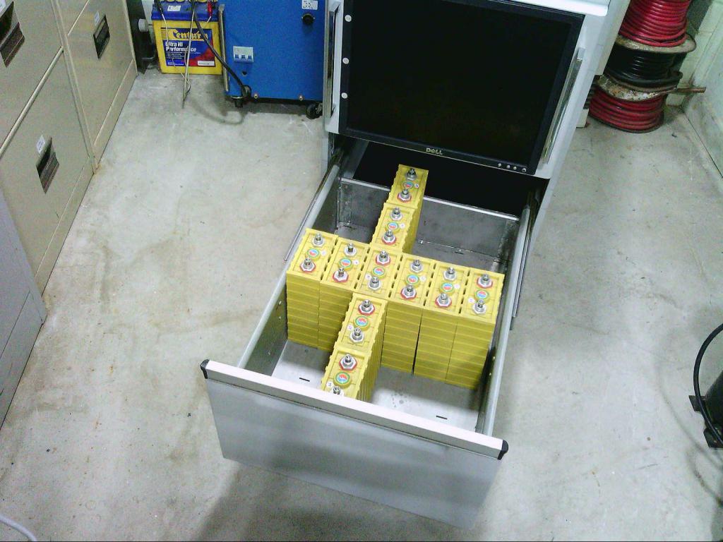
In my own case I worked out that thirty 60Ah Winston cells are a perfect fit into a standard filing cabinet drawer stacked 6x5 with about an extra 15mm to spare for heavy steel clamping plates down either side. Ā So I based my own system voltage on that, and its nominally 100v at 3.3v per cell.
For anyone that has a 48v system, this battery packaging could also be ideal, just parallel up pairs of 60Ah cells to get a 50 volt 120 Ah battery. This only works with the 60Ah Winstons. All the other sizes are completely the wrong shape, no matter how you try to arrange them. Of course a two drawer filing cabinet would be perfect for a very compact 50v 240 Amp hour battery
Nobody else has a 100v system, mine is a total freak. Higher voltage systems are usually designed for either 96v or more commonly 120v based on the tradition of connecting up multiples of standard 12v batteries. But with individual cells, there is a lot more flexibility. Ā Absolutely no problem in adding a few extra individual cells to suit your transformer, and of course those extra cells are also going to add some useful extra watt hours of battery capacity.
Its going to save work modifying that beautiful transformer which would be a shame, plus add something to the battery capacity. Edited 2019-11-17 09:27 by WarpspeedCheers, ĀTony.
wiseguy Guru Joined: 21/06/2018 Location: AustraliaPosts: 991
Posted: 06:11am 17 Nov 2019
Copy link to clipboard
Print this post
The filing cabinet sure is a neat solution with the Winstons. I was leaning towards a 96 or 120V system to match the likely voltage of a DIY E-car.
You asked me to try a lower voltage on the inverter to see if there is any evidence of Flux shift. The answer is no - I could not see any evidence of flux tending to saturation, it is only evident at the higher nominal voltage.
The flux tendency towards saturation I observed just draws a bit more average current on the offending half cycle. The choke I am using appears to stay well away from saturation so it just drives the transformer with as much current as required to balance the IR losses to any DC drive imbalance that exits.
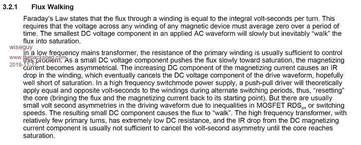
The following article is from a TI paper on inverters and seems timely.
I know Poida has stated that there cant really be a flux walking/saturation issue or we would know about it by now. Perhaps there are degrees of allowable flux imbalance - admittedly I suspect these degrees to be relatively small. Assume that the nano code outputs perfect LHS & RHS drive waveforms to the nano second (pun intended....)
Lets see how my inverter messes with the perfect drive signals. I have used opto FET drivers that have tolerances, there are on and off delay times and rise and fall time parameters.
The TI paper above says even RDS on and FET switching speed imbalances can be an issue - these would probably be an order of magnitude smaller than the effects of tolerances for the opto parameters.
It would appear to me that if we now assume the nano timing is a fraction less than perfect and add the RDS & FET switching times to the opto parameters I think it highly likely (guaranteed) that there is some degree of flux walking going to occur, like it or not.
Perhaps the opto FET drivers influence can be further minimised by measuring & matching them. I do not advocate that this is or will be required, just an option.
In reality, for my inverter, I did match the FETs into batches of RDS on and considering that the Optos were not matched at all, my inverter really works quite well. It is possible that tolerances have caused a flux offset in my inverter that hovers closer to saturation in one direction. Given that random minute changes in nano timing will exist I am thinking they probably cause the random saturation effects I am observing.
To clarify, the saturation effect I observe is a drift in the current waveform driving the toroid, which randomly causes a current peak to appear in the waveform coinciding with a change in the transformer hum - it is not catastrophic by any means and can probably be ignored.
I conclude that there are 2 options going forward - accept the imperfections warts and all and be happy and move on - so far it appears to not be causing anything to be alarmed about except an audible buzz from time to time.
The second option is as Warp suggested some time ago is to have an active system that tries to balance the flux by looking for current peaking in the toroid primary and backing off the drive slightly, I cant actually see Poida rubbing his hands together with glee at the prospect of doing this either - and I cant blame him. It means unbalancing the code for every second half cycle to pull back from saturation - I agree it has knobs on it.
I intend to progress on with inverter testing now and ignore the random changes in hum of the toroidal tranny. I saw and investigated a problem which I now conclude to be a minor irritation that I think can safely be ignored.If at first you dont succeed, I suggest you avoid sky diving.... Cheers Mike
renewableMark Guru Joined: 09/12/2017 Location: AustraliaPosts: 1678
Posted: 06:57am 17 Nov 2019
Copy link to clipboard
Print this post
If you suspect the nano, why not run the power board from a 8010 based control board to see if there is a difference.
I can't look at waves in detail like you can, but can state that the bigger the choke I ever put on the less hum and problems there were.
The big iron double aerosharp one that runs the house unit got the same size in the caravan unit, having such an oversized choke in that little system made it silent.
The big house one has a double iron and a double ferrite in series.
Certainly not a scientific approach but it works and can't kill either of them now.Cheers Caveman Mark Off grid eastern Melb
Warpspeed Guru Joined: 09/08/2007 Location: AustraliaPosts: 4406
Posted: 07:02am 17 Nov 2019
Copy link to clipboard
Print this post
Flux walking in switching power supplies is far from an unknown problem, and there are two commonly used solutions.
The first is using current mode control on an inner feedback control loop so that gate drive in each direction is terminated when an identical peak current is reached in each direction. If the transformer starts drawing higher peaks in one direction, that side has its duty cycle shortened cycle by cycle. Its a fairly simple analog solution, but software generated pwm is a whole different ball game with other issues.
The other way to flux balance is to connect a capacitor in series with the primary. That will ac couple the transformer and balance the volt microseconds in either direction. The capacitor then may assume a slight dc voltage, but the volt microseconds are then balanced automatically.
A series capacitor is only practical at fairly high voltages, such as direct off line switching power supplies operating at 350v to 400v. At 48v dc and maybe a hundred amps of primary current, any series capacitor would need to be a very large, and expensive, and very special component. Its just not a practical solution for us.
I did buy some linear Hall effect sensors a while back, and contemplated attaching one to a transformer to see if flux walking could be detected that way. Still have the sensors here, but never did anything with them.Cheers, ĀTony.
wiseguy Guru Joined: 21/06/2018 Location: AustraliaPosts: 991
Posted: 08:04am 17 Nov 2019
Copy link to clipboard
Print this post
Tony, I was referring to the toroidal flux walking at 50Hz not the 20kHz switching stuff. The first paragraph states "any magnetic device" is susceptible to this. Current control would need to be derived from the 50Hz toroidal current sensing. How to apply that to the nano is maybe near impossible and maybe more suited to a DSP chip. My post was more aimed at providing some insight to others with various degrees of technical know how.
Just for your interest I put an EMC clamp over one primary winding lead to see what it did (also to the 1.5kHz ring) the answer was nothing, I then ran 6 turns of wire through it. By connecting a diode first one way then the other I could move the saturation point better and worse - I was contemplating an active external flux steering circuit, but decided to just accept the flux wandering.
Mark it was not supposed to be a criticism or complaint, just an investigation into something I observed, to find out how much of an issue it was.
The 8010 I am confident also has this problem - OZtules and others have commented in the past about changes in transformer hum that comes and goes, even on the idle.
The extra average Power drawn during the worst of the hum is ~ 1.5W on the idle and about 2W at 1kW. The room I am working in is dead quiet so the change in hum is obvious.
I agree that a gapped Iron core choke whilst a bit lossier has a good saturation characteristic and would certainly help to minimise noise.
I suspect that when this is in a box and not right by my ear the hum will never be heard again anyway.
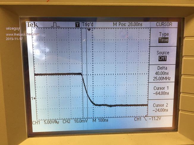
Whilst posting I might as well put up some pictures of the low side gates I probed during operation.
The first image is the gate showing the fall time at the actual Gate & source. Note the signal is 12V drive and -5V when off. The fall time from 90% above ground to 10% is ~ 40nS.
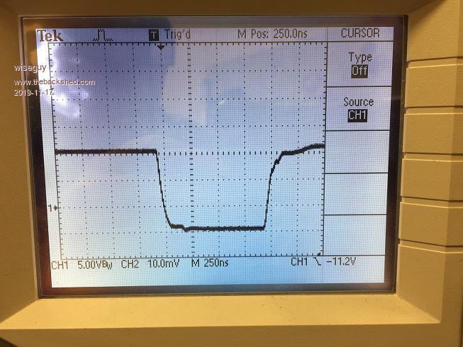
The next pic shows the gate fall and rise for relativity.
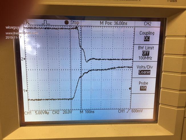
The next pic upper trace shows the fall of the Drain of the low side FET as its gate is driven high (lower trace).
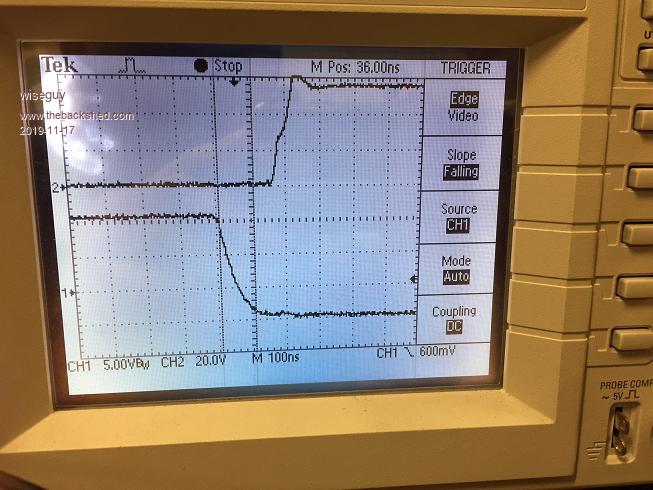
The last picture is the reverse, FET turning off (upper trace) as gate is driven off (lower trace).
I have no complaints on the waveforms, they all look good to me. At some stage I will remove the -5V bias to see if it really makes any difference and is worth the extra few bits to do it.If at first you dont succeed, I suggest you avoid sky diving.... Cheers Mike
Warpspeed Guru Joined: 09/08/2007 Location: AustraliaPosts: 4406
Posted: 08:30am 17 Nov 2019
Copy link to clipboard
Print this post
Yes you are quite right, the flux walking effect only shows up at 50Hz in the transformer.
But its produced by errors in the 20Khz pwm where the duty cycle in one direction may be very slightly different to the duty cycle in the other direction. ĀThat is all averaged out by the choke, but it produces a slight dc displacement in the whole 50Hz waveform, one whole half cycle becomes very slightly larger than the next whole half cycle.
I have never seen it done, don't even know if its possible, but how about feeding a corrective dc current into a third winding on the transformer ? That could be isolated with a series choke so it would not interfere with normal transformer ac operation.
The actual error may be tiny. But the problem is it ratchets up every cycle. An 0.1% difference after one thousand cycles would drive the flux 100% in one direction.
All it might need is 0.1% of dc fed in to counteract the original small difference to offset the ratcheting up effect. Edited 2019-11-17 18:48 by WarpspeedCheers, ĀTony.