
|
|
Forum Index : Electronics : Nano Power Inverter - Roll Your Own Style
| Author | Message | ||||
renewableMark Guru Joined: 09/12/2017 Location: AustraliaPosts: 1678 |
I didn't think I was implying you were doing either, it was just a suggestion if you suspected one drive method to possibly try another to rule something out. That's my caveman method, like I said certainly not scientific, but can sometimes give a result.....if you try enough  Cheers Caveman Mark Off grid eastern Melb |
||||
| wiseguy Guru Joined: 21/06/2018 Location: AustraliaPosts: 990 |
When you keep referring to yourself as a cave man it conjures up a picture in my mind of your man cave - that is where a cave man lives   or maybe  yeah I know....dream on..... If at first you dont succeed, I suggest you avoid sky diving.... Cheers Mike |
||||
mackoffgrid Guru Joined: 13/03/2017 Location: AustraliaPosts: 460 |
If anyone here is a caveman it's me, but my cave doesn't look anything like that  |
||||
| mackoffgrid Guru Joined: 13/03/2017 Location: AustraliaPosts: 460 |
Hi Mike How did you go with your UCC3808 circuit and RM6 - pcb windings? How much power can you get out of each secondary? I have the need for 400 - 500v working isolation and on checking the various products on the market almost none of them will guarantee a working voltage above 240Vac / 340 Vdc or there abouts. Creepage would need to be addressed, perhaps with kapton and potting. Cheers Andrew |
||||
| wiseguy Guru Joined: 21/06/2018 Location: AustraliaPosts: 990 |
Hi Andrew, just after I got the PCB's back, our new house was in its final stages and has diverted most of my attention ever since. We installed 13.2kW of solar panels all north facing. I essentially designed a huge north facing roof and created a house underneath. The inverter is a 10kW Fronius 3ph unit that runs bloody hot on a hot day - almost untouchable, the fans fairly scream - not how I would accept a final design & glad its in the garage. The average power created currently is around 80kwh per day. ĀThis is quite different to what I went to the solar shop to buy, once I started talking about home made inverters and batteries I could see their eyes glazing over.....FYI if I put in a 15kW Fronius Āto tap into the occasional 13.2kWH peak power, we calculated a 10 year payback before I see a cent after paying the extra money for the bigger inverter. They sold me on the concept of using the grid as your battery. If you use no power you will receive a cheque from AGL for around $4+ thousand dollars per year. Every kWh I use before what I return to them is a bonus to me as I miss out on ~19c but dont have to pay the ~45c from the grid. However when the grid stops so does my 80kwH per day and my lights go out. This isn't exactly operating off grid I know but whilst I am organising batteries, building a better bigger toroidal tranny and putting the inverter into a case in air conditioned comfort its not all bad. Back to your question, I only rigged up a single pcb with the 2 windings and drove it from the UCC3808. I had to up the frequency to ~ 300kHz from memory to run at its most efficient (well away from saturation). From memory the idling current was ~ 6 - 10mA. ĀWhen testing my inverter that uses 4 x HY4008's per leg the current to each gate drive section under full drive was ~ either 100mA input per leg (8 FETs) or 100mA total from 12V. ĀI will revisit & update this in the near future as I am finally seeing some clear air ahead to "play" again. If you want I am happy to revisit the design and aim for greater clearances for your application. ĀMaybe there is scope to thin the tracks further and maybe even add another turn or two in the process. I can fit at least 4 PCB's in the core so 8 isolated windings is a possibility, I agree with the Kapton suggestion and intended to use it also. ĀWhat is your application & have you measured the actual drive requirements ? - I thought mine would be over double what they actually are. I also ordered a dual channel fully isolated tektronix 25mHz unit from the good ol USA, old technology but probably better than the current chinese equivalent. So looking at high side gate drives at the same time as the low sides without releasing smoke from the FETs or CRO will be a possibility soon. Edited 2020-01-22 08:58 by wiseguy If at first you dont succeed, I suggest you avoid sky diving.... Cheers Mike |
||||
| BenandAmber Guru Joined: 16/02/2019 Location: United StatesPosts: 961 |
Wiseguy I don't understand a lot of what you're talkin about But I am very excited anyway can't wait till you get settled in be warned i am good parrot but Dumber than a box of rocks |
||||
| mackoffgrid Guru Joined: 13/03/2017 Location: AustraliaPosts: 460 |
I was thinking of doing the same thing except I was thinking of an Industrial shed and building a house under it. Situations change.So you pay 45cent per kWhr ? and receive 21c ? Fronius have a good name, solar installers speak well of them. I have a 5kW Fronius here in Brisbane. It has a fan, noise doesn't bother me but the fact that it needs it does. AS for isolated converters, as soon as you get above 240Vac or 340Vdc, it gets harder to obtain a converter that is designed for that voltage. The Adum5020 will guarantee that it will work at 500Vdc (from memory) for 50 years so that's ok but it cost around $10 and is only 30% efficient. Murata have some converters that won't go as far as saying they have a working isolation above 240Vac but they specify they have 4mm creepage. Probably works. My next WarpInverter should be okay with the aliexpress units but I am looking into making a WarpInverter and other stuff that will run off an electric Car / battery. This takes us into the low 400 volt area (charge voltage) and a friend of mine is making his around 500V. So a converter that has a designed isolation becomes interesting. My requirements for H-bridge is the same yours I think, 12v in and multiple 15 out. I prefer 4 outputs for a H-bridge. If I'm driving lots of Fet/Igbt's I would add more converters. I wonder what the output quality is like if I add a 5v linear reg on the output for isolated sensors or comms drivers. One requirement I have coming up is for an isolated ADC. Is this a probe or a scope? Sounds good either way.  Cheers Andrew |
||||
| Warpspeed Guru Joined: 09/08/2007 Location: AustraliaPosts: 4406 |
The whole issue of generating multiple isolated dc supplies can be a rather difficult nut to crack. A couple of years ago I was asked to repair a mate's variable frequency motor drive that had stopped working. I discovered that a small glued in toroid that generated four 12v isolated supplies had broken loose and was just dangling on the very fine wires. One of these wires eventually broke and the drive stopped working. I rewound the whole thing and put it back together and the drive was then back in action again. 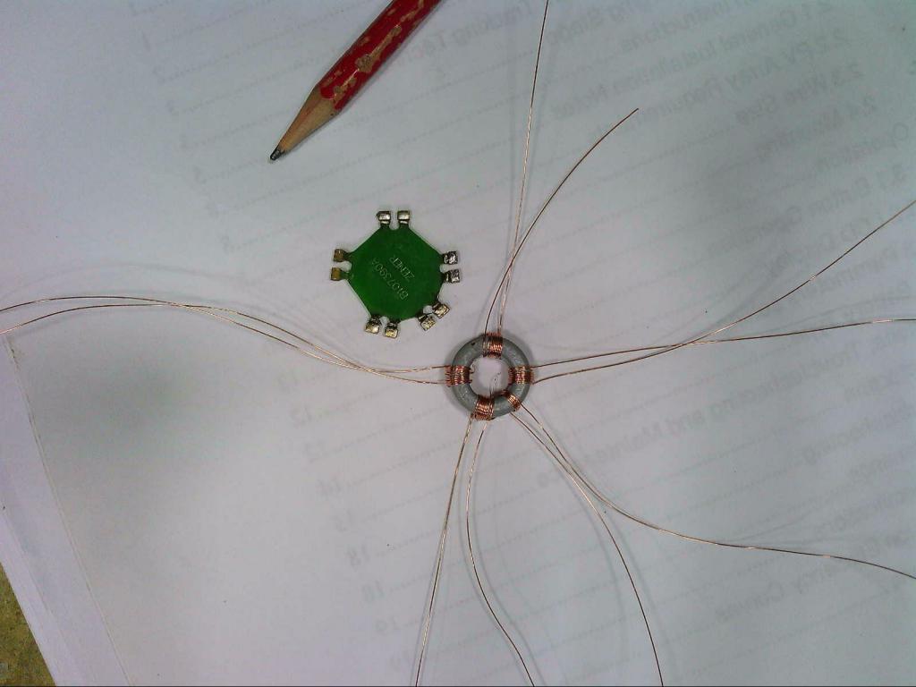 That started me thinking, because that little toroid put out some really nice clean well regulated square waves, and it was so very small. Several years previously I had attempted to make something similar using a much larger very high permeability ferrite toroid, and the result was truly awful, and very discouraging. 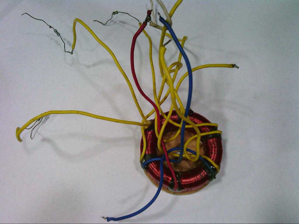 I reverse engineered that small drive toroid, and it became obvious that the plastic coated core, whatever it was, could not possibly be ferrite. I eventually worked out that it must be amorphous metal. That has enormous permeability, very high saturation flux density and it will run with comparatively few turns for what it does. In the smaller sizes its not that expensive either. https://www.alibaba.com/product-detail/40-32-15-cased-amorphous-toroidal_1451233913.html?spm=a2700.7735675.normalList.10.78143701y8BLN8&s=p I never pursued this any further because the little two dollar Chinese postage stamp sized power supplies are a far simpler solution for a high dc voltage inverter. But for some things amorphous metal toriods offer some really interesting possibilities. A free sample should be available if you are interested. Edited 2020-01-22 12:15 by Warpspeed Cheers, ĀTony. |
||||
| wiseguy Guru Joined: 21/06/2018 Location: AustraliaPosts: 990 |
That was my main gripe, needing a fan + too hot to touch = lost efficiency. The Tektronix A6902A is a dual channel isolator unit. It has isolated probes + electronics and connects to your CRO and gives DC to 25MHz B/W. I just checked latest AGL data - feed in tariff is now 18c/kWh and supply 40.381c/kWh so yes they pay us half what they charge us for the same kW ! I'll revisit my RM6 transformer design soon. I use ~ 1000v/mm for approx breakdown voltage - yes potting would help too. Interesting re car battery for storage - I was going to do the same but I was thinking around the 96 - 120V range (DC Brush motor) on a roll your own auto design that would power my HV inverter - same inverter different mosfets and toroid. If at first you dont succeed, I suggest you avoid sky diving.... Cheers Mike |
||||
| wiseguy Guru Joined: 21/06/2018 Location: AustraliaPosts: 990 |
Hi Ben sorry that most of my discussion seems to border on secret mens business stuff its just in my DNA. Feel free to query anything you dont get, someone or me will answer your query soon enough - if you're lucky enough it will be someone else...... If at first you dont succeed, I suggest you avoid sky diving.... Cheers Mike |
||||
| wiseguy Guru Joined: 21/06/2018 Location: AustraliaPosts: 990 |
Tony thats a good looking jellyfish its a shame it didnt work better to reward you for your efforts If at first you dont succeed, I suggest you avoid sky diving.... Cheers Mike |
||||
| Warpspeed Guru Joined: 09/08/2007 Location: AustraliaPosts: 4406 |
Ah! but even dud projects can often be instructive. Mike, love your Tek A6902A isolator, should go very well with your new Rigol cro. Cheers, ĀTony. |
||||
| mackoffgrid Guru Joined: 13/03/2017 Location: AustraliaPosts: 460 |
Blimey. Real incentive to plaster the rooves with solar !!! (I pay 19.2cents and receive 16cents) |
||||
| wiseguy Guru Joined: 21/06/2018 Location: AustraliaPosts: 990 |
Tony I chickened out on upgrading a Rigol DS1054Z, did a deal with the local Emona agency and got a fully optioned DS1104Z-S Plus for $750 inc GST ex demo but still just like new & with full warranty. It has a 2ch built in 20mHz arbitrary waveform generator so I reckon I got good value with zero chance of bricking it lol. Compared to my TDS220 its like upgrading from a Cessna to a 747 cockpit..... will take a while to find my way around and get fully comfortable with what its telling me. I agree with the dud projects, its like when they said to Edison; What! you tried 1000 different ways to make an incandescent lamp and you have nothing to show for it so far? his response was; on the contrary, I have learned 1000 ways not to make the lamp. If at first you dont succeed, I suggest you avoid sky diving.... Cheers Mike |
||||
| mackoffgrid Guru Joined: 13/03/2017 Location: AustraliaPosts: 460 |
Whoa, a heap of posts slipped in. What a good sign off line Well I get lots of instruction I wish I could join the Rigol party. I'll be very interested how that isolation amp goes. Yes, I was looking at the gif of that winding pcb to see if there was scope to increase creepage :-) These days the likes of JLCPCB can do much finer tracks and separations. Much obliged with whatever you come up with. Ben: Mike has indicated that he's thinking of a 96v inverter which is where these inverters should be going to. I have faith that this version of the SPWM inverter will be gold standard in DIY SPWM inverters. As I have indicated I'm going up in the voltage stakes with the warpVerter as well, first at 235v then at 360V - so plenty to get excited about - I hope  BTW Tony, (who first convinced me to go to 96v - the rest is my fault) I watched a video of a guy (pro-trainer) pulling apart a chevy volt battery pack, and he happily touched each side of a 100v module like it was a 12v car battery to demonstrate the lack of shock, he felt nothing. cheers Andrew |
||||
| Warpspeed Guru Joined: 09/08/2007 Location: AustraliaPosts: 4406 |
I have had countless full contacts right across 100v dc over the last couple of years, and never felt anything at all. But then I am an old fart with dry skin. But in my youth I once received a very nasty bite from just 12v dc. I was up to my knees in sea water helping to launch an aluminium boat. Happened to reach over the gunwale and accidentally touched the battery terminal with a wet hand. I will never forget that. Cheers, ĀTony. |
||||
| BenandAmber Guru Joined: 16/02/2019 Location: United StatesPosts: 961 |
At 96 V what are you guys going to do for the charge controller At that voltage would you need mppt be warned i am good parrot but Dumber than a box of rocks |
||||
| mackoffgrid Guru Joined: 13/03/2017 Location: AustraliaPosts: 460 |
Ben, the voltage of the system is immaterial to whether MPPT is warranted. I'm not very fussed about MPPT in an offgrid situation. Where you have limited space or scope for solar panels then MPPT may become more important. All grid tie inverter incorporate MPPT as they're optimising financial return. Cheers Andrew |
||||
| Warpspeed Guru Joined: 09/08/2007 Location: AustraliaPosts: 4406 |
Ben, Make Sky Blue have a 96v mppt charge controller, and I have seen others. Anything over 5Kw would be much better off at 100v. You certainly had a tremendous win with that ! I think you are going to be very pleased with that new Rigol. Edited 2020-01-23 13:18 by Warpspeed Cheers, ĀTony. |
||||
| wiseguy Guru Joined: 21/06/2018 Location: AustraliaPosts: 990 |
Ok finally received the 90 degree R/A 0.1" dual row header from good ol Aliexpress. ĀExpress hey? more like slow boat from China... Decided to assemble the little transformer for isolated Gate drive supplies as a vertical mount assembly. Total board area used is 0.7" x 0.3" or 20mm x 10mm. Here are some pics of the finished assembly, the next step is to mount it on a PCB, add the diodes and caps and some loads to check its performance. 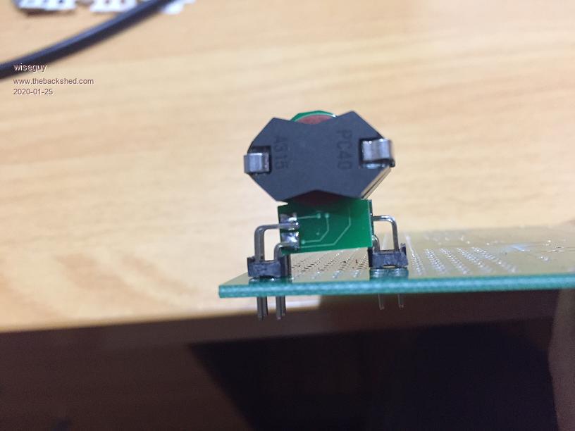 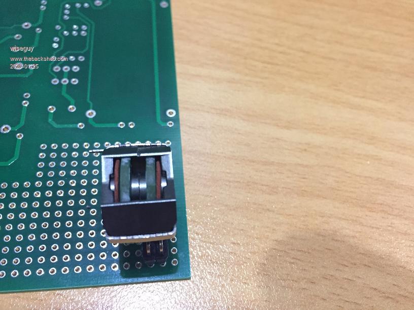 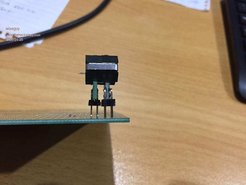 Note in the middle picture the 2 x red fibre washers added for insulation between the windings and the ferrite. Also note the generous gap between the 2 winding PCBs. The gap can be reduced by 2.5mm to ~ 1.2mm to reduce board area slightly (smaller parts under 10mm height can be placed under the transformer assembly closer to the small footprint mounting) One PCB has the 2 x 8T windings for the high side FET drive circuits, the other has a 7T drive winding and the other 8T winding for the 2 low side FET drive circuits. Edited 2020-01-25 07:33 by wiseguy If at first you dont succeed, I suggest you avoid sky diving.... Cheers Mike |
||||
