
|
|
Forum Index : Electronics : Nano Power Inverter - Roll Your Own Style
| Author | Message | ||||
| wiseguy Guru Joined: 21/06/2018 Location: AustraliaPosts: 995 |
I now have a third Eltek Flatpack to install in my home made rack housing which will give me 6kW of DC power supply. I am running all three in parallel from the one 240V outlet. I am well aware that with this setup most of my work and testing will be limited to 2.4kw. ĀHowever for starting a compressor or drop saw it does have a much healthier surge rating and I hope for a lower droop when starting them, than what I currently see. Of course when running them from 3 phases I will have the full 6kW of continuous power available for more extended high power testing. This first video is starting the compressor from the inverter - note the dip in bulb intensity before it recovers See Here The next video is running the compressor straight from the same 240V mains AC power source that the 2 x Elteks were powered from to see the native mains droop See Here The lamp has less of a dip in intensity and a bit quicker recovery straight from the mains. ĀI then conducted an experiment, the result surprised me. I got the two identical toroids wired the two LV windings to each other and fed the 240V into one toroid and then put the bulb and compressor on the 240V of the second toroid. ĀWant to guess what happened? Well the bulb brightness dipped alarmingly and the compressor Āstruggled to turn over and gain speed. Of course I forgot to video this as I wasn't intending to post the result. So the nano inverter is doing a good job of trying to boost and regulate the output back to where it should be. ĀIt is also a good hint that the power throughput (impedance) of the toroidal 240V output may be starting to struggle with the compressor load. As I am not using a battery source my instantaneous current availability from the Elteks is nowhere close to a battery source, as the Elteks each have ~ 40A current limiting. For that reason I do not expect stellar performance, but adding the 3d Eltek will be my first indication whether its a drooping DC source issue or a Toroidal impedance issue. My next video will be with the third Eltek added, to see if the bulb intensity dip can be improved. ĀIf there is no improvement I will put the 2 Toroidal transformers in parallel to lower the overall impedance and run the same inverter test again - I suspect this will give the better result, albeit with higher idling current. Edited 2020-01-25 09:07 by wiseguy If at first you dont succeed, I suggest you avoid sky diving.... Cheers Mike |
||||
Revlac Guru Joined: 31/12/2016 Location: AustraliaPosts: 961 |
The second video looks a lot like what my old bench grinder used to do on grid power, used to dim the lights when switched on. Does your air compressor motor have a centrifugal start switch for the start winding? The start up current would be substantial? Cheers Aaron Off The Grid |
||||
| wiseguy Guru Joined: 21/06/2018 Location: AustraliaPosts: 995 |
Hi Aaron, I believe it is a centrifugal switch start & yes the instantaneous current is substantial. Thats why I like it as a test load, if the inverter survives and it runs the compressor it tells me the inverter will easily start a fridge or other similar load. The next ornery load is a 1300W drop saw that also resembles a short for a few tens of milliseconds until it gets some speed up. Edited 2020-01-25 12:59 by wiseguy If at first you dont succeed, I suggest you avoid sky diving.... Cheers Mike |
||||
| noneyabussiness Guru Joined: 31/07/2017 Location: AustraliaPosts: 506 |
I use my " big aircon " , the compressor startup is brutal... i had some lesser quality mosfets on a ozinverter on my 5kw oil cooled transformer, it would blow them everytime... had to run it from the grid .. the 7 hy4008 per leg board i have now dims dramatically but survives everytime now.. i have a few " sensitive " loads i put on ups's to ride through any dips... but so far just the big aircon triggers them... They are online apc jobs that i got for free from the dump... the things people throw out... I think it works !! |
||||
mackoffgrid Guru Joined: 13/03/2017 Location: AustraliaPosts: 460 |
Sounds like a bunnings compressor  Well done so far  What CAD did you use to draw those little windings PCB? They look like a tedious job. |
||||
| wiseguy Guru Joined: 21/06/2018 Location: AustraliaPosts: 995 |
I also like the APC UPS units, another set of batteries usually yields another 5+ years of good service - their size belies their weight though, for the power they are very reliable and compact but weighty. My contention is that the choke plays a much more important role in our inverters than they are given credit for. The choke essentially integrates the squarewave HF pwm into a LF current at the fundamental 50hZ, the transformer then translates this into whatever voltage you have designed it for. Although they are a series connected circuit they both play an important role. For a brutal load the PWM will ramp up in a very short time, if the chokes inductance, impedance & saturation are not adequate (and the Toroidals impedance) added to this, collectively the FETs may be driving a very low impedance load at the fundamental HF which will seriously challenge the FETs. If at first you dont succeed, I suggest you avoid sky diving.... Cheers Mike |
||||
| wiseguy Guru Joined: 21/06/2018 Location: AustraliaPosts: 995 |
I used Altium, it has a draw ARC function. I specified a 6mil track and draw a ~300 degrees arc and then add a second such arc but move the radius by 12 mil. This gives me a 6/6mil track and clearance - the lowest sizes that our Chinese friends do at low cost. If I specified 3/3 the cost goes from $5 to $130 ! The rest is by tweaking the ends of the arc as required and some fiddling around to cross couple each turn to the next. I am considering another design of a 4 layer PCB winding to double the number of turns per winding. This allows a lower switching freq. & improves efficiency a bit. I also propose fully routing them to size and shape during manufacture. Currently it is a bit of a pain cutting them out & shaping them to fit the core, It did prove the concept works fine though & still much better than manually winding. ĀThese days I probably have more money than time left so I should use my time more wisely & not waste time that $50 will fix !! Edited 2020-01-26 11:37 by wiseguy If at first you dont succeed, I suggest you avoid sky diving.... Cheers Mike |
||||
| wiseguy Guru Joined: 21/06/2018 Location: AustraliaPosts: 995 |
Okay, bolted another Eltek2 into the rack and wired the outputs in parallel and tried the compressor again. This gives a total output capacity of ~ 110A DC before limiting The result can be seen here. The dip in lamp brightness is now comparable to the direct mains and a very favorable result with regard to the toroids capability. I guess there are a couple of ways to progress from here. I can build a second inverter PCB and drive the second toroid with it. Then develop a scheme to run them in parallel for heavy loads. After the load on the first unit exceeds say 3 or 4 kW, the second could be commanded to start. After the second units soft start is over a relay/contactor could parallel the secondaries (maybe I could use the Freq compare of the second unit to enable the paralleling?) then the inverters are sharing the total load. As the load decreases below 3/4kW the second unit is commanded to stop (soft stop) ready to go again later. I have most of the parts and PCBs already to hand. I will ponder this a bit more. Another way forward is to find out what it takes to break the inverter and then back off 30% and call that a maximum for the rebuild. Now I will go play with the little RM6 isolated DC gate power supplies from the PCB track windings, and get a feel for their max output in mA. If at first you dont succeed, I suggest you avoid sky diving.... Cheers Mike |
||||
| BenandAmber Guru Joined: 16/02/2019 Location: United StatesPosts: 961 |
None ya business if you're board is like mine it is horribly lacking in the capacitor Department By the way $113 on AliExpress for a 24 mosfet board. it is on sale right now It is not like mine it has a split heat sink on one side I will be ordering one here in the next couple days soon as I get the money up Back to the capacitor issues the little Ā4 mosfet board (poida the great) walked me through was horribly lacking also It had 2 450uf caps it had a hard time starting larger motor loads I replaced them with two 18000uf caps I also shaped 10 or 12 gauge wire and soldered it in over top of the tracks It made a gigantic difference in starting that little air conditioner I will be doing the same with my 24 mosfet inverter board As soon as I find a good deal on 8 10000uf or larger capacitors The problem is the heat sinks are too close together This is just one of the many reasons I really like Wise Guys boards On his you can use big caps little caps put them on top or bottom And the mosfets are pushed out to the edges of the board That means you can use just about any kind of heat sink ĀI have to go with 30 mm diameter 35 mm would come to close or maybe rub the heat sinks Now to the good part I just cannot get your oil bath inverter off my mind I honestly believe oil bath will be the future It will be maintenance-free !!!! dust builds up very quickly when you have a fan blowing I have been looking at Industrial buck-boost Transformers along with a oil bath Industrial case for a inverter board I want it to fit right in with any other normal electrical equipment I just can't get my mind off of it I really honestly believe it's going to be the future I'm sure the DIY guys that builds works of art we keep it as is but just regular everyday people would probably prefer the oil method with heavy duty industrial boxes I went ahead and subscribe to your Channel By the way this by no means is any advice to you none ya I'm sure you forgotten way more than I'll ever know Just stating my experience I think everyone on here knows the difference between me and you If they don't they have not read very much and need to catch up More youtube videos please! Edited 2020-01-26 15:11 by BenandAmber be warned i am good parrot but Dumber than a box of rocks |
||||
| mackoffgrid Guru Joined: 13/03/2017 Location: AustraliaPosts: 460 |
The youtubes are great Mike If you are going to find the point of failure make sure you have the camera on it  |
||||
| wiseguy Guru Joined: 21/06/2018 Location: AustraliaPosts: 995 |
Andrew, the reason I record video of these start-up events is also to capture the smoke and flying bits which thankfully have so far eluded me. If I did not catch it on video I would not bother rebuilding it again the same, just to recapture the event - there is just the one chance. I may choose not to drive it to destruction just for the pleasure (?) of seeing it go bang. ĀPerhaps once the FETs begin heating up to say 30 degrees above ambient with no Fan it could be concluded that the losses are starting to have detrimental effects that will only become worse with increased load/torture? ĀI am surmising that if I plot input power versus output power for increasing loads I will find a knee where the losses start to accelerate - it will be interesting to find out whether it is the choke or toroid that might need a tweak to extend that point. ĀI imagine the IIR losses of the FETs will also have a point where the efficiency losses increase more rapidly. Before I tell you the results of my PCB track winding RM6 results, I have taken some measurements from my inverter which may be of general interest to others also. With no gate switching signals applied, but the opto drivers being powered up from the little isolated power board, the total supply input current requirements from the 12V supply line is ~40mA. ĀI know this converter requires ~ 20mA on the idle, so each FET Opto driver circuit must require ~ 5mA. FYI I placed a 0.1R resistor in series with the isolated PCB12V supply so all the current measurements are input current requirements only and due to converter losses are guaranteed to be close to but conservative estimates of the output requirements. With the inverter being powered by the 53.5V rail and normal PWM gate signals applied, the isolated supply input current increased to 98mA. This is an increase of 58mA split between 2 lots of 4 lower fets and 2 lots of 4 upper fets at the nano pwm drive frequency ~ 20kHz. ĀThis means that the Miller effect is being driven along with the native HY4008 gate input capacitance. As my Fet isolated supply pcb has 2 isolated upper drives (4 FETs each) and a common low side drive (8 FETs total) it is fair to say that the current requirements of each group of 4 Fets is around 58mA/4 or 14.5mA. Ā So both high sides are 14.5mA and the common low side supply is 29mA for the 8 lower side FETs. Note: An individual HY4008 FET switching 53V at 20kHz with a 12V gate supply using a decent FET driver and in my case 2R2 gate resistor requires ~ 3.6mA of extra supply current (in addition to the FET driver idling current). The small RM6 bias transformer works as expected for this application. ĀI have tested the 2 x isolated upper supplies can deliver 25mA each and the lower supply to 50mA. ĀAmple for my requirements. ĀThe voltage out of 1 secondary is 11.97V delivering 50mA. What are you planning to use these isolated supplies for, what switching freq, V+, FETs - and how many etc ? I have not loaded the isolation unit drastically as I sense it may be already be adequate just as tested. Should you need more current tell me what you reckon that will be and I'll re test it. If for a Warpverter though I would expect current requirements at that switching frequency to be much less than at 20kHz? Edited 2020-01-27 16:15 by wiseguy If at first you dont succeed, I suggest you avoid sky diving.... Cheers Mike |
||||
| noneyabussiness Guru Joined: 31/07/2017 Location: AustraliaPosts: 506 |
B&A , just to answer your capacitor question (?) I have installed about 100k uf of caps externally, so the dips i see i believe are the momentary blip as the eg8010 feedback catches up.. And the oil bath is awsome, temperature changes are slow, even under high load. As i said previously, i used an old aerosharp case ( its waterproof, so oil proof) easy to use other brands, it was just what i had on hand. I think it works !! |
||||
| mackoffgrid Guru Joined: 13/03/2017 Location: AustraliaPosts: 460 |
Hi Mike I'm grateful Mike. I will have a number of needs coming up. They are all based on battery voltage or charge voltage up to the low 400 volts. My earlier low voltage Warpverter bridge drivers would use much less current than yours, Rg's of 100ohm each and generally low frequency. I vaguely remember crudely measuring it at about 10 or 15mA per quadrant. I also remember that the overall power consumption went up by approx. 1 watt per inverter, warpverter having four inverters. (That was for driving low voltage Mosfets whereas IGBTs will be used in the high voltage bridges). I intend on using IGBT modules with built in drivers for the big inverters. The data sheet shows they need 15v at typical 5mA and Max of 10mA per quadrant and the lower bridge elements are combined. As power supplies for isolated sensor circuits. One in mind is an isolated IIC adc. ADS1115 and aDum1251 ; respectively 200uA and 6mA plus a linea reg. Or if I need a faster device the ACPL-C87B uses 15mA, plus whatever opamps are needed. Mains Charger circuits, PFC stage and Buck stage. Depending on what chokes I can scrounge I'm going to run the IGBTs at around 15kHz. Each stage at about 10amps RMS but I haven't selected devices yet. Solar panel strings, OC voltage of low 500v. If I can I'll power these with TL191 but if I have to PWM mosfets then an iso converter will be needed. So 100mA total and 50mA for a winding sounds pretty good. Isolation and creepage is utmost and I'm happy to drop the number of outputs to achieve clear isolation and creepage performance. So quite a shopping list. Thanks Andrew |
||||
| Warpspeed Guru Joined: 09/08/2007 Location: AustraliaPosts: 4406 |
Just to have something to compare all this to, my Warpverter has sixteen of those little postage stamp sized power supplies for all of the gate drivers, all of which require very close to four watts combined on the 100v dc input side. So 250mW input power per isolated gate supply. The main control board is the big load, mainly from the sixteen opto isolators, eight of which might be on at any moment. Each opto led requires 5v at 10mA. So total opto isolator load at 5v is around roughly 80mA at 5v. The whole control board consumes about 120mA at 5v or 600mW of dc. On the 100v input side its just under one watt. So with the four transformer primaries disconnected, my idling power for all of the running electronics is just a tad under five watts. Cheers, ĀTony. |
||||
| wiseguy Guru Joined: 21/06/2018 Location: AustraliaPosts: 995 |
I needed to get more serious about finishing my inverter, moving has gone well and now getting settled into the new house. I earlier bought two largish toroidal transformers from ebay, which were good value but they had issues. The secondary wires on one were very "wobbly" and I did not really trust them. ĀBoth had a secondary voltage of 35.8v from 240VAC in, it would need batteries 1.414 larger or 50.62V MINIMUM for 240V out. I contemplated just using a few more cells and running a system voltage higher than 48V, but then I scored a Sirius super cap 48V nominal energy storage system, for minimal cost, that is fully charged at 54V Max and fully discharged at 44V. ĀIt is only 3.6kWH but that should get me through the night after a free re-charge during the day. 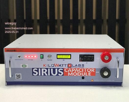 Normally I refer to primary as the magnetising exciting winding (240VAC) however from this point onwards I will refer to the 240V as the secondary and primary as the 48V inverter driving winding, even when feeding 240V into the TX for testing.. So I bit the bullet and set about fixing the dicky leads on one transformer and to lose some primary turns on both, to allow operation down to 44V. ĀThis entailed unwinding a large part of the primary until I was able to effect a repair on the secondary stubs that had about 10mm of multistrand wire available & that had had some leads poorly connected & soldered - dressed up poorly by someone before I bought them. 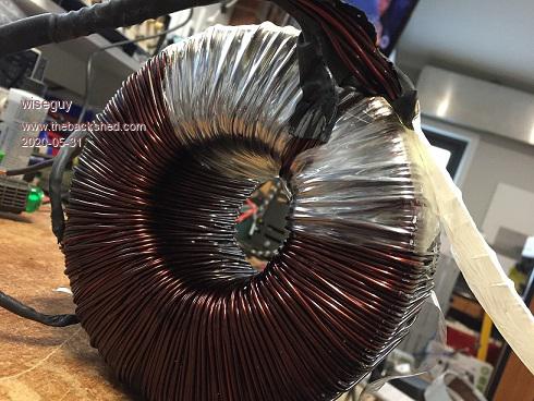 Unwinding....UhOH 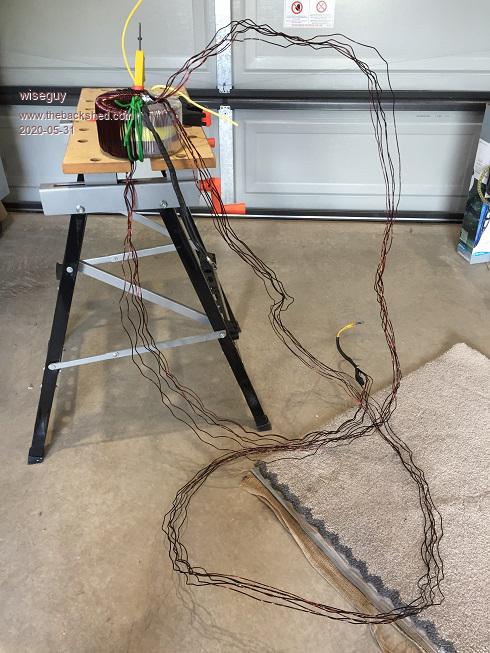 Just a few strands holding the 240V winding 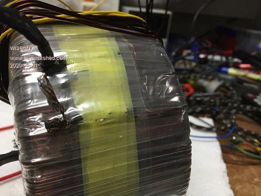 Repaired with soldered bootlace ferrules 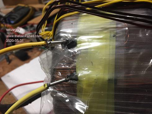 Fixed 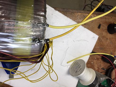 Second from left is smaller diameter than others 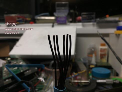 Ready to rewind with guides 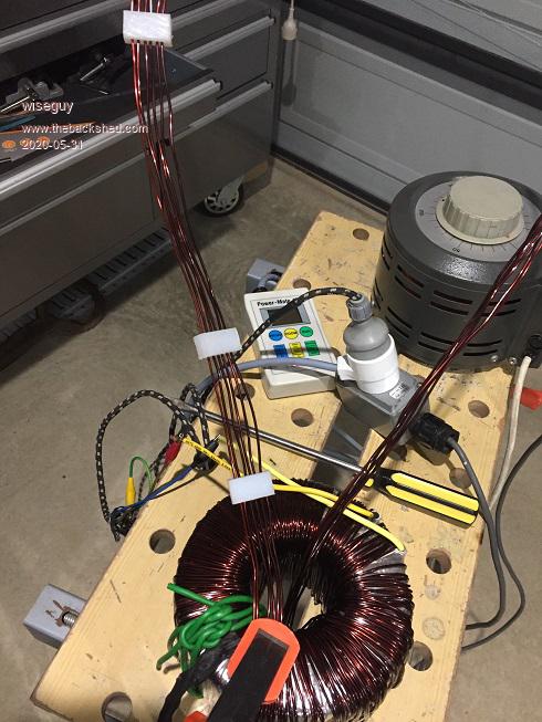 The actual voltage required for 44VDC to AC is 44 x 0.7071 = 31.118VAC. ĀSo I needed to unwind/rewind back enough turns to reach the required ~31V. The primaries were 6 in hand of 5 x ~1.85mm ands 1 x 1.65mm. ĀAt about this point I attached a temporary 10 turn winding to determine the volts per turn. I was pretty surprised to find 7.74V with 240V on the primary. ĀThat gave me 310 turns on the secondary and 40 turns, yielding 30.9677V required for the inverter drive winding. ĀSure there is relatively low magnetising current, but these turns seem a lot more than the Aerosharp toroidals that were being wound by others here. ĀMost ended up with about 1V per turn, whilst mine is close to 0.774V per turn. Unwinding the primary a long way was relatively easy going but I could sense that re-winding the 6 strands of 1.85mm wire at once was going to be a right bitch and it was easy to pick where my re-winding effort started - its a bit akin to refolding a large map - it usually never refolds back up looking the same as before you unfolded it. ĀI never counted the turns it was too difficult with their complicated scatter/overwind method so as I got close to the right number, I carefully applied mains and checked the primary voltage which was 25.7, 5.4V shy or another 7 turns required. Having completed both units, next I joined the primaries together, ensured I had the secondary's phased correctly and applied 240V to one secondary, measuring from the other secondary was within 0.1V of 240V (much less than 1 turn) Āensuring parallel operation would be fine. Next I mounted the 2 transformers into an old Aerosharp box, one at each end. 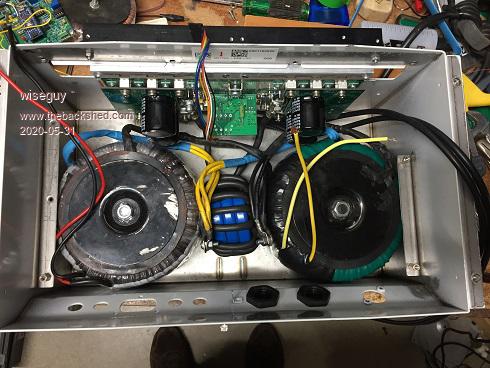 Then hacked the chassis to fit my inverter board/heatsink power stage and fitted a small aluminium panel to mount the nano and some DC & AC circuit breakers. ĀIt did not feel quite right squeezing ~ 5-6kW of inverter into what they had previously allowed for ~ 1.6kW but it squeezed in. ĀNow lugging the box around, which is unbelievably heavy for its size, is a real task. 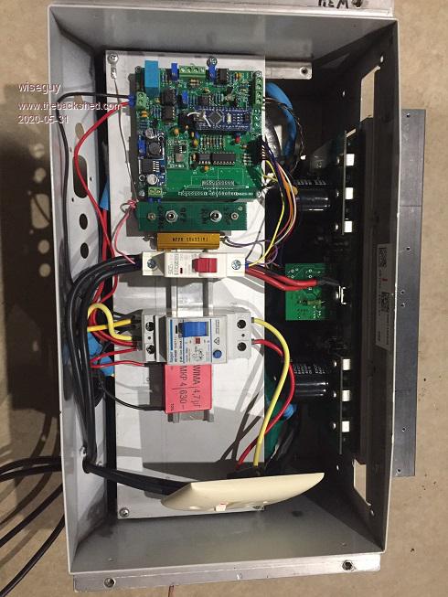 It worked first time, running off first one, then 3 x Elteks (~110A overall capability), I could easily start my compressor concurrently with a 2.4KW fan heater, idling along at about 80A input current. ĀAt this stage I am uncomfortable with the 3 switches for pre-charge, turn main CB on then hit the run switch and then get it right in the reverse manner later to shut down. ĀMy next investment will be one of those wonderful LEV2 solenoid/relays that can switch 900VDC and 500+ amps. ENG_CS_5-1773450-5_sec7_LEV200_0313_5-1773450-5_Sec7_LEV200.pdf Then I can use just one small single toggle switch to charge the capacitors, when charged up, the solenoid will be driven in to enable the high current feed and the nano will then ramp up the output. Soon I will get brave enough to join the inverter to my 48V energy storage unit, perhaps then I will get my wife to turn it on...... One concern is that I am relying on a Chinese DC circuit breaker that does not provide any polarity information with the breaker switch and I know these contain magnetic parts to quench any arc from developing - provided the current flow is in the direction as designed. If things go wrong im wondering how long it will take to undo a bolt retaining one of the lugs to the pack lol. ĀI think I should invest in a 200A DC forklift fuse as a back up before connecting the pack - any other suggestions ? Edited 2020-05-31 01:15 by wiseguy If at first you dont succeed, I suggest you avoid sky diving.... Cheers Mike |
||||
| wiseguy Guru Joined: 21/06/2018 Location: AustraliaPosts: 995 |
On Thursday I had a 20A 3 phase outlet wired into my workshop. ĀThe next part will be to build a breakout box to 3 x 240V sockets (one to each phase) so I can run the 3 x Eltek 2kW rectifier/power supplies for an extended time at 4, 5 & 6 kW to check overall efficiency, heat build up etc. The logistics of making this set-up power the house of an evening is somewhat problematic. ĀThe genius electrician has shared power & lighting across the house using all 3 phases. ĀYes my LED lighting is partitioned & running from all 3 phases. ĀLets see now 50 LED lights at 10W ea = 500W so if they were divided equally ~ 160W per phase - what a waste of 3 x 10A circuit breakers, wiring and the brainpower for this solution, that if running from just 1 phase would still have a spare nearly 2kW of capacity. So the easy (?) way to drive the house ATM is to connect L1 & L2 & L3 together (note to self, switch outlet to off first......), and together with the common neutral connect them to my inverter output, turn off the street connection, turn on the inverter and enable the outlet switch, voila one phase driving 3 in parallel all lights and power point work - there are no 3 phase motors or appliances in the house - the ONLY reason for the 3 phase connection was to allow me to feed up to 15kW back to the grid. Only allowed to feed 5kW per phase max. Now the next good part, ensure the outlet is switched back off in the morning before the 10kW Fronius 3 phase inverter driven by the roof solar kicks in and complains about the L1,L2,L3 shorted output. Yep this plan has knobs on it, I look forward to some suggestions from the many clever people here how to redesign my twisted thinking into a better way to do all this, preferably automatically. In some ways it would be easier to be off grid totally but if I want to enjoy cool evenings in 35 degree summer evenings after dusk in the workshop and house there can be up to 7kW of A/C load before induction cooktops & oven & microwave are also considered. They could all suck the life from 3.6kWH in about 10-15 minutes flat. ĀI dont want to lose the grid, as it earns me money each quarter and it can run AC all night if it has to, but I do resent being given 18c per kwH for feeding energy back in the daytime to then paying 44c/kWH in the night for what I need to use from the grid. If I am going to go off grid totally I would need some serious kWH capacity to keep my wife happy and in a similar manner to which she has become accustomed etc.... Last part - the energy geniuses are talking about turning off our solar grid feed inverters as they are producing too much energy during the day causing localised high grid voltages and network instability. Why not change the timeclocks for the "off peak power" devices to be on peak power drains to help equalise by using the excess daytime energy, also the sun usually doesnt shine at night so it is a waste to then create energy to run all the off peak stuff. Seems to me they need to re think what and how to do this better to suit todays situation. Edited 2020-05-31 02:02 by wiseguy If at first you dont succeed, I suggest you avoid sky diving.... Cheers Mike |
||||
| Warpspeed Guru Joined: 09/08/2007 Location: AustraliaPosts: 4406 |
One thing to consider when connecting L1, L2, and L3 in parallel is that all of the combined return current then flows back through the same common neutral. You have three twenty amp phases, plus a twenty amp rated neutral. So the total power must be limited to twenty amps total, or you could potentially burn up the neutral. The neutral has no fuse or circuit breaker over current protection, so its a potential hazard to be aware of. Cheers, ĀTony. |
||||
| noneyabussiness Guru Joined: 31/07/2017 Location: AustraliaPosts: 506 |
fuse holder Proper dc rated fuse holder.. fuses Fuses... I think it works !! |
||||
renewableMark Guru Joined: 09/12/2017 Location: AustraliaPosts: 1678 |
I use this type Congrats on getting it working. Re the start up procedure, it's no big deal having to pre charge. I have the same setup on my house and van Āunits. The house one obviously just runs 24/7 and never gets turned off. The van one I just leave going on stand by. All it's doing is keeping the caps charged, which is bugger all energy requirement. When the unit is required, just a quick press of the momentary button starts up the control board and it's going in a couple of seconds. That saves mucking around with the pre charge. Re the phases, would it be possible to wire all the house requirements onto one phase? and then have an Auto changeover switch between the grid power and your inverter. Edited 2020-05-31 09:35 by renewableMark Cheers Caveman Mark Off grid eastern Melb |
||||
| Warpspeed Guru Joined: 09/08/2007 Location: AustraliaPosts: 4406 |
That can certainly be done if its all switched at the main power board. The problem is that sometimes there may be a three phase feed out to a shed or a garage, where the inverter is located. That is the system I have here. I can feed power back to the main board, and that is not a problem because its thee 35 amp phases with a 35 amp neutral. Nothing I have in the house draws anything like 35 amps, so not a problem. Cheers, ĀTony. |
||||
