Notice. New forum software under development. It's going to miss a few functions and look a bit ugly for a while, but I'm working on it full time now as the old forum was too unstable. Couple days, all good. If you notice any issues, please contact me.
wiseguy Guru Joined: 21/06/2018 Location: AustraliaPosts: 995
Posted: 05:07am 18 Oct 2021
Copy link to clipboard
Print this post
When I look at the CRO trace all the way from a single cycle visible to a 5 second sweep everything looks normal. The envelope begins at nothing ramps to operating amplitude and then tapers back to nothing at turn off.
I restart and get a grunt as it appears to achieve normal amplitude, even though I cant see any visible overshoot or distortion occurring. I'm still hunting for the elusive difference between the two cases - it must be very subtle, except for what the ears hear.
If I interrupt the soft stop by turning the run switch back on before the end of soft stop, it immediately truncates the tapering off soft stop envelope and begins a new soft start from zero and I never get a grunt at the end of the restart/soft start.
Intuition says, if anything, after not completing a soft stop and then restarting you might expect the grunt issue should/could occur then, but it never does - hence I am a bit stumped. That is why I've asked Poida what differences there are between a soft start from shutdown and a soft start restart from an interrupted stop that was heading for shutdown. Edited 2021-10-18 15:09 by wiseguyIf at first you dont succeed, I suggest you avoid sky diving.... Cheers Mike
Warpspeed Guru Joined: 09/08/2007 Location: AustraliaPosts: 4406
Posted: 05:44am 18 Oct 2021
Copy link to clipboard
Print this post
If there is no obvious violence going on in the current waveform, I would not worry about it.Cheers, ĀTony.
poida Guru Joined: 02/02/2017 Location: AustraliaPosts: 1388
Posted: 09:25am 18 Oct 2021
Copy link to clipboard
Print this post
I have to say that I have seen toroids that have experienced "life changing moments" or blown powerboards as we know it to now always make a loud hum during the soft start - which they did not do before.
I spent some time looking at this and it seems it has to be remanence even though the iron core is well made with a very soft characteristic. So it should not have much remanence - but they do.
I tried to hit the torid with a big pulse of current in one or the other direction in an attempt to give it some remnant flux. Then soft start it and see the primary current. Only once could I give it a permanent field and then it did give a louder hum during soft start. Usually it was a test with inconclusive results.
I have ended up with a couple of inverters, one is nearly silent, one has a good bit of hum, etc. Both have similar chokes etc. But the one with the bigger hum is the build that uses a toroid that was involved in a few powerboard blows. I changed the choke but the hum remains. I took the hummy toroid and tested it with various power boards and it always was a bit noisy.
I am sure Madness, Warp et al here will want to contest my view but I think the Aerosharp 3kW toroids CAN TAKE A MAGNETIC FLUX and RETAIN SOME.
Further to the hum during slow start: There is no way to increase the flux during slow start without putting more + or - flux compared to the other. There has to be more of + or - at any time during the ramp up period. Otherwise there will be no ramp up. I have seen about 100 times the primary current waveform during the soft start and I have wonder what is happening and why. I think it's got to do with small imbalances of the + and - flux and as I said, you have to have it if you change the operating flux level. (pick a cycle and give it more. You can not pick BOTH + AND - cycles to increase at the same time, since we are driving + and - cycles ALTERNATIVELY)
I explored modified nanoverter code that permitted small changes to the power of the + cycle compared to the - cycle. In other words the code could drive a small DC bias into the primary in either direction. I could make the soft start hum disappear with small trims of DC bias. Different toroids needed different trims. Further evidence that there is a remanent magnetization...
In summary:
there will be hum during soft start. It's not the nanoverter code's fault, the EG8010 also does it. I think it's the nature of the beast.
The soft start hum is attenuated or dampened by the LC filter on the primary winding. If you choose a too low resonant freq. the hum can persist a bit longer. And you make the hum louder. The hum volume is proportional to primary current. And it's proportional to rate of change in primary current.
I found a resonant freq of about 30Hz or more to be best. 15 Hz was bad and inverters blow up. Warp thinks 75Hz is optimal.
You can excite this hum by hitting the 240V output with a sudden load such as switching in a large transformer. Things hum a bit for a few seconds then settle down.
This hum is the exchange of energy in a LC resonant circuit between sources and sinks.wronger than a phone book full of wrong phone numbers
poida Guru Joined: 02/02/2017 Location: AustraliaPosts: 1388
Posted: 09:40am 18 Oct 2021
Copy link to clipboard
Print this post
Wiseguy: sorry to see the inverter blew. "It was all going so well.." as we all note prior to the fireworks.
The compressor I used to test the victim inverter (4 x 4 HY4008 FETS) has since died. It will not run now. Maybe the cap, maybe the windings. But the peak power load of a starting induction motor is a real test. I think I saw 11kW peak from the "2HP" motor. Your calculations (in a PM) are spot on and I wonder why it blew when it seems there is headroom for this load level.
Once you get it right, you get an inverter that will do the job for years. I found that to be a mixture of relief and boredom. (what to explore next?)
I am so glad to have two of them. One to drive the house power and one for experiments and entertainment.
The house inverter has just clocked over 2 years without issue. This is a 10x better price performance than the Victron I had. I think it will keep going for a while yet.wronger than a phone book full of wrong phone numbers
Warpspeed Guru Joined: 09/08/2007 Location: AustraliaPosts: 4406
Posted: 05:27pm 18 Oct 2021
Copy link to clipboard
Print this post
These remnant flux troubles would very likely be solved if the design operating flux level is kept low enough to allow for a possible flux doubling effect, without hitting hard magnetic saturation at start up.
Repurposing commercial transformers such as Aerosharps without rewinding is certainly attractive, but these may also come with some inherent limitations due to a cost cutting design (less steel and copper).
I would be really interested to know if any of these start up issues have arisen when home wound toroids designed around a one Tesla flux swing are being used.Cheers, ĀTony.
poida Guru Joined: 02/02/2017 Location: AustraliaPosts: 1388
Posted: 09:14pm 18 Oct 2021
Copy link to clipboard
Print this post
the toroid in the noisy inverter is energized to about 235V AC on it's 240V (or whatever) output windings. It needs 27 turns on the primary for this 48V DC inverter.
What would the flux level be for this, Warp?wronger than a phone book full of wrong phone numbers
Warpspeed Guru Joined: 09/08/2007 Location: AustraliaPosts: 4406
Posted: 09:24pm 18 Oct 2021
Copy link to clipboard
Print this post
What is the physical cross sectional area of steel in the core ?Cheers, ĀTony.
Revlac Guru Joined: 31/12/2016 Location: AustraliaPosts: 961
Posted: 11:01pm 18 Oct 2021
Copy link to clipboard
Print this post
@Mike, can you measure the DC current the inverter uses during startup? and another again at restart? see if its different. Typically the transformer will make a little more sound when loaded, obviously yours is not loaded at startup, this should show when the start up current is measured, should be the same when running. Is there is a current rise when the grunt happens.Cheers Aaron Off The Grid
wiseguy Guru Joined: 21/06/2018 Location: AustraliaPosts: 995
Posted: 10:40am 19 Oct 2021
Copy link to clipboard
Print this post
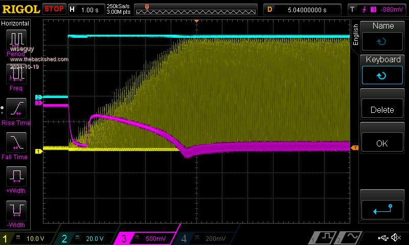
Hi Aaron, (late reply, busy day...) yes there is a bit of extra current. Because I have 40,000uF the actual current from the power supply is a bit filtered. Blue is the 48V supply Yellow is switching power envelope Purple is supply current through 0R22 resistor in series with minus of 48V supply. The above picture shows the extra current drawn at the end of ramp up when the grunt happens. The initial dip (increase) of current at the beginning of the trace was the capacitors charging after turn on, then an increase of current until overshoot & grunt.
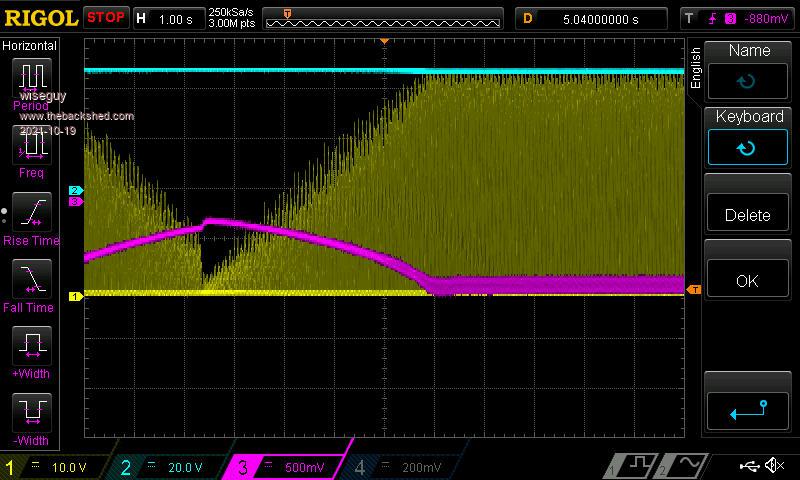
Ramping down then Run switch set to on again before ramp down finish
You can see the current lessening (rising - its neg current, more = less lol) Then the run switch is set on again and the new ramp up begins. This time no overshoot (undershoot - sheesh) of current.
This happens 100% of the time when starting from stopped or restarted during soft stop. It is not an occasional grunt or no grunt it is 100% predictable.
Last point of interest the current is slightly higher after the grunt - no yellow trace visible, after the restart yellow trace is just visible - I will go measure actual current soon to see if it really is different. Edited 2021-10-19 20:45 by wiseguyIf at first you dont succeed, I suggest you avoid sky diving.... Cheers Mike
wiseguy Guru Joined: 21/06/2018 Location: AustraliaPosts: 995
Posted: 10:53am 19 Oct 2021
Copy link to clipboard
Print this post
Peter, I will answer your longish post by agreeing with essentially everything you said.
But we diverge slightly on one point. Why does a cold start always grunt and draw the extra current when an interrupted (truncated) soft stop occurs and is set to ramp up again from zero it never overshoots and grunts.
These two cases as stated to Aaron are 100% reliable & predictable.
I hear that you are running the same section of code (you didnt actually say those words I think) so it should not be any different - but it is & I am baffled at the moment. I havent given up - when I find something I dont understand it rattles me - everything happens for a reason sometimes the reason can be very elusive.
I don't change anything in my hardware except for the position of the stop/run switch which goes to the nano.....
Keep smiling
edit: re looking at the above pictures it appears the ramp up of current was a little faster ~ 3 to 3.5 sec compared to the ramp of the restart ~ 3.5 - 4 Secs from approx the same starting level of current - is that a hint ? The yellow envelope also reflects a slightly faster ramp up on the grunt trace.
By the way when I restarted after one partial ramp down the inverter started a very scary ~ 400-600Hz very loud Buzz - I thought I had fried more FETs but a power down and not being able to measure any shorts it restarted fine again - another hint ?
Im not blaming your code at all, just trying to state objective facts as they appear/happen in case it might lead to an answer or subtle explanation. Edited 2021-10-19 21:06 by wiseguyIf at first you dont succeed, I suggest you avoid sky diving.... Cheers Mike
wiseguy Guru Joined: 21/06/2018 Location: AustraliaPosts: 995
Posted: 01:39pm 19 Oct 2021
Copy link to clipboard
Print this post
My thinking on this differs a bit from yours - maybe I'm barking up the wrong tree - I sometimes wonder if I'm even in the wrong forest.......
I have always said that for a perfect balanced sinewave, each 90 degrees of a 360 degree waveform must be exactly equal. The only reliable way I can see to do this is to only create a look up table of 90 degrees and then to fill in the other 3 quadrants with a copy of the first 90 degrees - obviously reflected/inverted as required to resemble the 360 degree sine wave.
Next if increasing or decreasing the sine level, would be to modify the whole 360 degrees with a fixed operator/modifier, again so the contents of the 4 quadrants have been changed exactly the same as each other.
In this manner each 180 degrees of 360 degrees adds and minuses exactly the same energy & flux leaving a net flux of zero in a perfect world for every 360 degree set. This is true regardless of constant amplitude, ramping up or ramping down if the same rules are applied.
It is easy for me to write this but creating the code that does this may be easy, difficult or next to impossible to implement it but its the only way I can see to avoid flux wandering, is to micro manage/control each set of 360 degrees. If I could write code this is what I would try to create - maybe not exactly as written above but I needed to paint the picture of how it would work in practice.
When I said leaves a net flux of zero, I conveniently ignored hysteresis - there will I think always be some flux remaining until the next 180 degrees modifies it, but I don't think this changes the principle of its function, as it always starts and finishes each 360 degrees from a non zero flux. Edited 2021-10-19 23:50 by wiseguyIf at first you dont succeed, I suggest you avoid sky diving.... Cheers Mike
Revlac Guru Joined: 31/12/2016 Location: AustraliaPosts: 961
Posted: 03:05pm 19 Oct 2021
Copy link to clipboard
Print this post
Mike, better late than never. Looking at your earlier post and pictures, I thought I might have an idea, but after reading a few more times, maybe not.
A few thoughts, You have a different start up procedure than others, if I remember correctly, I did like that idea and it would save me a button and 2 switches. Now, a lower bus supply voltage could also result in more current used, I take it that caps are fully charged and full current from the battery or supply is available, before the inverter is switched on (soft starts). The only way for this to happen is if the voltage was lower between where the supply is measured and the H Bridge itself, but I can't see that (or it shouldn't be) happening. The restart would already have full supply voltage and ready to go, Now why is the start up ramp time longer or shorter on either two starts ? I have never tried to measure the start ramp compared at 48v or at 58v to see if it is different, I assume it is, I think from memory the start ramp with the 8010 did vary a bit depending on the vfb setting, but once set, never noticed it change.
Definitely some reason something is going on there but I can't put My finger on it.
I'm could be barking up the wrong tree also, its late now and I better get dinner. Going to have a play around with a ready made commercial transformer soon, check some numbers and so on.Cheers Aaron Off The Grid
Warpspeed Guru Joined: 09/08/2007 Location: AustraliaPosts: 4406
Posted: 09:55pm 19 Oct 2021
Copy link to clipboard
Print this post
This scares me a lot.....
First silly suggestion, does the ramping process override everything else, is there any way the voltage feedback could be playing silly buggers ?
Second even more unlikely suggestion. Way back in the dim past I had an early Warpverter sometimes very occasionally throw a very brief fit during startup. It very rarely did it and never when I had test equipment hooked up trying to catch it.
That inverter ran reliably for a couple of years, then one day it blew up for no apparent reason. Replaced everything, and it blew up again. It took several sets of mosfets, and a lot of bad language before I discovered the cause.
The metal can of the quartz crystal had shorted to the copper pads underneath. Fitting an insulating spacer fixed it, and no more violent freakish startups. It appears that any sudden mechanical shock could briefly short the crystal, and set off a chain reaction of transformers jumping around and the crystal oscillator going spastic.
I cannot begin to guess what your problem may be, but careful monitoring of everything will eventually reveal something very different when it burps. Finding it may be a very long and frustrating exercise, but you WILL find it.
Don't dismiss dry joints and faulty connections from plugs and sockets. Klaus can relate some real horror stories.... Edited 2021-10-20 07:58 by WarpspeedCheers, ĀTony.
wiseguy Guru Joined: 21/06/2018 Location: AustraliaPosts: 995
Posted: 12:08am 20 Oct 2021
Copy link to clipboard
Print this post
Aaron, after reading your last post I realised I needed to clarify something to you - and in doing so it clarified something to me.
In my quest to try to work out what might be influencing my inverter, I decided to make a small change. All these latest tests are done with full 48V supply always running and attached to the H bridge Power bus. In that fashion the nano controller is also always powered up - I had wondered if the removal of nano power during a complete stop might have influenced the issue.
As I wrote those words a little light bulb went off in my head. Duh if the capacitors are already charged up why is there a jump in current at the beginning of a full startup ? The answer is that it was actually the pull in current for the solenoid before it steps back to a much lower current to hold it in.
That is why it doesn't look like an exponential capacitor charging curve. This little anomaly should help to emphasise that you need to question everything you are seeing in detail to ensure you really understand what is happening. My focus was what happened from the beginning of the ramp, not before.
The last piece of the puzzle for extra clarification - why does the 48V suddenly jump on the blue trace from zero to 48V. Well mr clever decided to use what was the input 48V to the solenoid normally, as a convenient trigger and monitor point for the 48V as when the solenoid closed after setting the run switch to run when it went from open circuit (where the 48V supply is usually attached) to the 48V now applied to what is normally the 48V output side. Clear as mud hey......
If this all looks like double dutch just tell me and I will re-attempt to explain in better engrish.If at first you dont succeed, I suggest you avoid sky diving.... Cheers Mike
Revlac Guru Joined: 31/12/2016 Location: AustraliaPosts: 961
Posted: 09:34am 20 Oct 2021
Copy link to clipboard
Print this post
Thanks for the clarification, that helps. I was hoping there would be a light bulb moment for someone, and the relay did sort of through a spanner in the works when I was looking at the details. You would be well aware about what a relay coil can do to influence any surrounding circuit, most of the time this can be easily fixed
Is there any other ways you can try and power it up (SAFELY) with different voltages, within the limits, with or without caps, go through the process of elimination, sort of depends on what spare parts you could swap in or out to see if anything makes a difference, you have probably done some of this already, but I have to ask, or I keep thinking about the "What If" and "could it be" scenario.
Do you have a spare transformer to test with? small E I or anything with the correct voltage, might make a different sound.
At the moment I am out of ideas, more time to think, might come up with something later.Cheers Aaron Off The Grid
poida Guru Joined: 02/02/2017 Location: AustraliaPosts: 1388
Posted: 10:12pm 20 Oct 2021
Copy link to clipboard
Print this post
short answer: No. Not during the first part of the soft start when the output voltage is less than the setpoint. The output voltage will be increasing steadily up to the point where it is near equal to the setpoint.
long answer:
The ramp up (soft start) from zero output to the AC voltage setpoint takes something like 3 seconds. I do not know the exact time and I think it's unimportant. Reading the below code you will see it's 2.5 seconds.
Here are the things that happen after the inverter "run" command is seen on the Nano's run/stop pin.
Some variables are initialised. The soft start counter is set to zero. This counter may only be zero, through to 251. This counter is incremented by 1 each 1/2 cycle so it will increase by 2 every cycle of the 50Hz.
This counter is used to determine the AC output amplitude. The amplitude = Max_amplitude * (soft start counter) / 250 So we can see the amplitude will start at 0 and progress potentially to maximum AC output after it reaches 250.
Further code takes this amplitude result and will reduce this to suit the needs of maintaining the required AC setpoint's voltage.
Let's look at some code:
if(uf == 1 ) // this will execute at 100Hz { // it runs at near zero volt crossing of AC output uf=0; ac_setpoint = 0.55; // for same Vfb as EG8010. change AC output voltage via Vfb voltage divider trimpot if (oen == 1) sst++; // slow start. If output is enabled, keep starting up. sst = output pwm% or approx. voltage. if (sst > 251)sst = 251; // stop increasing when sst has got to the end of slow start. when = 251, this enables PID. See below.. if (oen == 0) sst--; // if stopping, slow stop if (sst <= 0) // once fully stopped, no more changes to sst needed { sst = 0; cbi(PORTD,5); // pull IR2184 shutdown LOW to disable gate drive output } else sbi(PORTD,5); // pull it HIGH, to enable output
In the above, first a test is made asking, is it time to change the amplitude if needed? uf = 1 then it is time and the code then sets it to 0 to stop it running again, until the next 1/2 cycle.
oen = 1 if the inverter is commanded to RUN. oen = 0 if the command is to stop
ac_setpoint is a variable that is similar to the EG8010 internal 2.5V feedback quantity. This code tries to keep the AC voltage, after processing = 0.55 We have a trimpot that processes the AC voltage as we like, increasing it or not. This is how we obtain our required output voltage.
the important variable is sst. Slow STart When the inverter is started, sst = 0 and each 1/2 cycle, sst will be increased by 1.
sst is limited to increasing only to 251 If the inverter is commanded to stop, then sst is reduced by 1 each 1/2 cycle Again limits are placed on sst's value, clamping it to zero.
Since this code runs at 100 Hz, the behavior of sst should be clear. when running the inverter sst will start from zero, increase to 251 and stay there. It will take about 2.5 seconds to get to 251 When stopping the inverter, sst will reduce from what value it may be and arrive at zero.
If sst = 0, then the gate drive output stage is disabled. This ensures no gate drive even if there are input pulses present.
next code works out the PWM pulse width during the soft start and soft stop.
if(sst > 0 && sst < 250) // slow start timer counts to 250 with gentle ramp up, then switches over to PID control. (gulp!) { // sst can increase or decrease, giving the slow start and slow stop. if (oen == 1) // slow start? I think of it as de-gauss { if(ac_output < ac_setpoint) pwr += 1.0/250.0; // bang-bang control, should AC output reach setpoint prior to PID. else // During slow start need to ensure output is tracking setpoint pwr -= 1.0/250.0; // should output get close enough to matter. } else pwr -= 1.0 /250.0; // this will execute in slow stop }
pwr is the important variable. This ranges from 0.0 to 1.0 I use this to define the output voltage by multiplying it with the maximum PWM width. if pwr = 0.0 then pwm width = very small if pwr = 1.0 then pwm width is as wide as it can be.
if sst > 0 and sst < 250 (to be perfectly correct the code should be < 251) the code is executed. First I do a check, is the inverter commanded to run? Then we are soft starting. Firstly, ac_output is compared with the setpoint since we could already be nearly there or even over voltage. if the output is less than the setpoint, increase pwr by a small bit, 1/250 if the output is more than the setpoint, decrease pwr by this small amount The reason I do this is because during the 2.5 seconds of soft start, the inverter probably will get to the output voltage setpoint. So then the code will keep it there within some error range.
If the inverter is commanded to stop, then pwr will be reduced progressively each half cycle until it's zero.
now it's time to convert pwr to pwm width, in units of clock cycles
if (pwr > 0.99) pwr = 0.99; // clamp. Do math in floating point to prevent any integer overflow if (pwr < 0.01) pwr = 0.01; // it's slower. We could do clamp after conversion to int but it's your mosfets... vpwr = (int)((float)PPWM * pwr);// finally apply required PWM duty power factor to vpwr
I clamp pwr to reasonable limits, ensuring it is within 0.01 and 0.99 Then I obtain an integer value, of the maximum pwm pulse width, in clocks multiplied by pwr.
This is the new pwm pulse width the inverter WILL run on from now on.
So far so good with the soft start and the soft stop.
what about when sst = 251?
if (sst == 251) // once sst = 251, run PID. the above bang-bang control will NOT have executed, because sst = 251 { Setpoint = ac_setpoint; Input = ac_output; do_pid(); pwr = pwr + Output; }
I instead execute the above code, the PID control and use it to obtain the required value of pwr to maintainthe output voltage as close as possible to the setpoint.
The PID code does not run during soft start nor during soft stop since sst DOES NOT EQUAL 251.
A nice thing about the PID control is that the calculations are done using floating point and result in fine changes in pwr. This results in a closely controlled output voltage and zero light flicker.
If you put an incandescent light on the inverter's AC output and start the inverter, the light of course starts to glow brightly. Then it flickers a little while the soft start process is still in effect BUT output voltage has been already attained. Then when sst gets to 251 and PID is now in control, the flicker stops.wronger than a phone book full of wrong phone numbers
Warpspeed Guru Joined: 09/08/2007 Location: AustraliaPosts: 4406
Posted: 11:22pm 20 Oct 2021
Copy link to clipboard
Print this post
That all sounds fine...
Just playing Devil's advocate here Peter (thinking out loud).
How about power supply sequencing for all the minor supplies such as gate driver circuits, any other logic or sensing. Power up is usually pretty straightforward, but power down sequence and brownout can sometimes create some interesting situations.
As this problem is not always present or repeatable, its not likely to be anything really obvious.Cheers, ĀTony.
poida Guru Joined: 02/02/2017 Location: AustraliaPosts: 1388
Posted: 11:28pm 20 Oct 2021
Copy link to clipboard
Print this post
This is still a good question.
The slow start ramp up overrides all while the output voltage is less than the setpoint.
Once the output is more than the setpoint and the ramp up process of the soft start is still working, then output voltage is controlled by a simple bang/bang control method to ensure the output remains close to the setpoint.
After the soft start ramp up process is completed then control goes to the PID control loop.
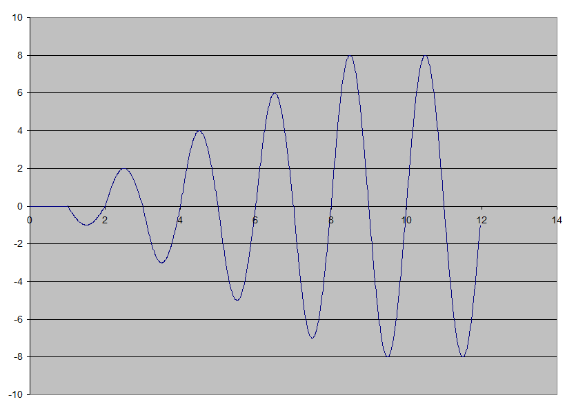
I made a simplified graph of the ramp up voltage as commanded by the code in the nanoverter. 7 half cycles from zero to full voltage, in this case 8 units.
It looks smooth doesn't it. But it's not.
Each 1/2 cycle, the peak increases by one. The increase is made when the curve is crossing zero, just as in the nanoverter code.
It has to increase sometime, somewhere in the curve or else there will be no ramp up.
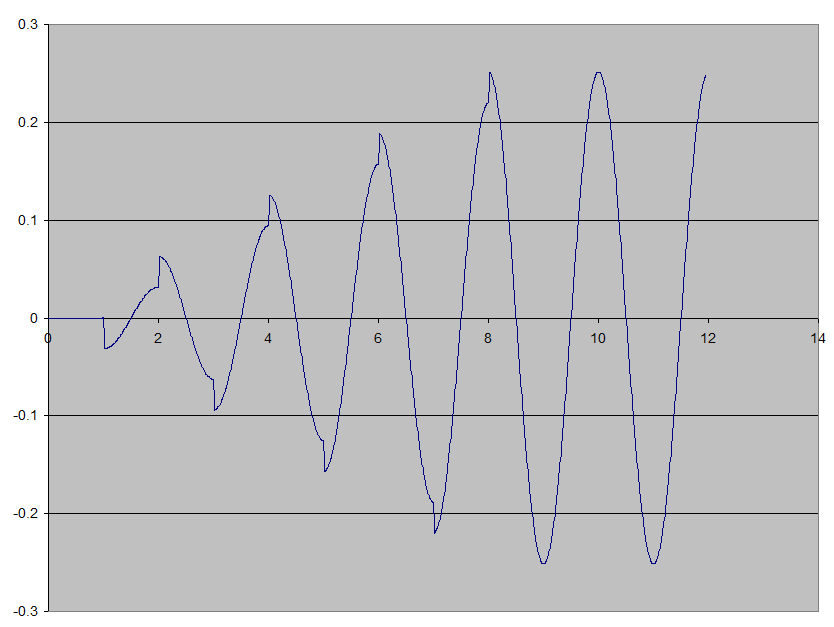
Below is the rate of change of voltage at any one time. (the derivative) I think the inverter output when unloaded is best modeled as a reactive load and so there is some inductive component. Inductors are sensitive to rate of change of voltage.
Look at the large changes of this curve at the peaks. They coincide with zero crossing voltages of the first graph This is when I apply the increase in amplitude or voltage.
I suspect these rapid changes in voltage change rates induce the growl.
I could modify the firmware to gradually increase the voltage over the 200 wpm cycles of each half wave. This will remove nearly all of these sudden peaks in change rate. Maybe no more growl?wronger than a phone book full of wrong phone numbers
poida Guru Joined: 02/02/2017 Location: AustraliaPosts: 1388
Posted: 11:43pm 20 Oct 2021
Copy link to clipboard
Print this post
My thoughts of power up
The nanoverter and picoverter have pulldown resistors on the pwm output from the nano. The DSO tests show this pin stays at ground during boot.
Once the code executes and gets to the stage where it can respond to the run/stop command signal, there is now a narrow, maybe 8 or 10 cycle pwm pulse present on the output pin. But also, the gate drive IC shutdown pin is asserted low, for shutdown of output by the firmware, via code that is executed very soon after boot.
these 8-10 cycle wide pulses end up not very wide and correspond to very low power levels. I do not think they are seen on the FET gates for long if at all.
All the above is after applying a good 5V supply.
The nano takes a a few seconds to execute it's program after the 5V is seen. During this time the pulldown resistor is grounding the pwm output pin on the nano.
My view is the nano will not drive an output via the gate drive IC unless the code is running and it has received the run command.
The nano needs only about 50mA @ 5V
I have not looked at brownout tests such as taking the 5V supply down to zero slowly while it is running. Maybe this weekend I can if you like.wronger than a phone book full of wrong phone numbers
Warpspeed Guru Joined: 09/08/2007 Location: AustraliaPosts: 4406
Posted: 12:13am 21 Oct 2021
Copy link to clipboard
Print this post
It might be a good idea to listen for any strangled screams from the microcontoller as the supply voltage is slowly withdrawn.
If all else fails, an undervoltage reset chip fitted direct to the gate driver enable might work, if the driver chip itself does not have an undervoltage lockout system. Many do, but if the gate driver chip is powered from say +12, that may not help if the +5v to the microcontroller sags first during power down or brownout.Cheers, ĀTony.