Notice. New forum software under development. It's going to miss a few functions and look a bit ugly for a while, but I'm working on it full time now as the old forum was too unstable. Couple days, all good. If you notice any issues, please contact me.
renewableMark Guru Joined: 09/12/2017 Location: AustraliaPosts: 1678
Posted: 02:50am 07 Oct 2019
Copy link to clipboard
Print this post
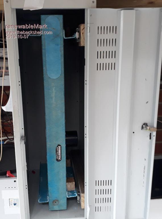
Back to this project now as the caravan inverter is all set up nicely. Made a bit of progress.
Cheers Caveman Mark Off grid eastern Melb
Warpspeed Guru Joined: 09/08/2007 Location: AustraliaPosts: 4406
Posted: 03:22am 07 Oct 2019
Copy link to clipboard
Print this post
That is going to be super accessible. Where do the transformers go ?Cheers, ĀTony.
renewableMark Guru Joined: 09/12/2017 Location: AustraliaPosts: 1678
Posted: 03:42am 07 Oct 2019
Copy link to clipboard
Print this post
Just below, it's a 2 door locker. I might take out the shelf between them and add some external bracing to keep it rigid.
The bottom will need some beefing up also with all the weight in there. Edited 2019-10-07 13:43 by renewableMarkCheers Caveman Mark Off grid eastern Melb
renewableMark Guru Joined: 09/12/2017 Location: AustraliaPosts: 1678
Posted: 07:46am 07 Oct 2019
Copy link to clipboard
Print this post
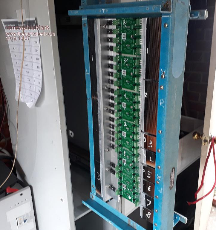
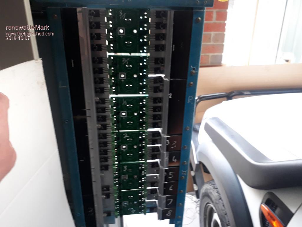
Here is is slid out, good access.
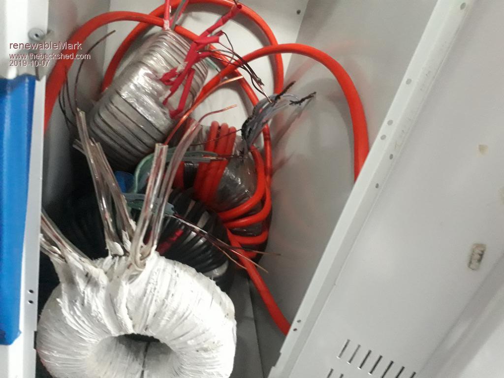
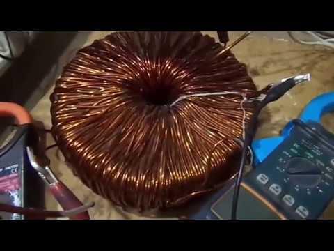
Here are the torroids just chucked in. I'll have to work out how to arrange them.
.Cheers Caveman Mark Off grid eastern Melb
renewableMark Guru Joined: 09/12/2017 Location: AustraliaPosts: 1678
Posted: 07:59am 07 Oct 2019
Copy link to clipboard
Print this post
The torroid in the front may confuse some. I normally use black, but this one got white polyurethane (leftover from caravan repairs) It still needs a mylar wrap.
Instead of using epoxy to glue up each layer I use polyurethane. It sets like rubber and the final torroid is less prone to humming. This I figure will give it a longer life as it's insulated better.
They do however hang onto a certain level of heat.
The one that runs the house in a 8kw madinverter never goes below 16c even in winter, but the heatsinks certainly do. In winter the heatsinks in the morning may be 3c and the torroid 16c.
There is always that residual heat that gets held when using polyurethane, but once the heat does get to the outer surface, it does dissipate quite well. Fans rarely need to come on, at least not with the loads we put on it. Only stinker hot 40c days when both air cons are going do the fans come on.Cheers Caveman Mark Off grid eastern Melb
Warpspeed Guru Joined: 09/08/2007 Location: AustraliaPosts: 4406
Posted: 08:05am 07 Oct 2019
Copy link to clipboard
Print this post
Easiest way might be a heavy steel plate with four large castors bolted underneath, and the transformers stacked vertically. That way the locker sheet metal sees none of the weight. That is pretty much how I did mine.Cheers, ĀTony.
renewableMark Guru Joined: 09/12/2017 Location: AustraliaPosts: 1678
Posted: 08:58am 07 Oct 2019
Copy link to clipboard
Print this post
Yeah, that sounds good, where it's going it will just stay put, so no need for castors, but the sub floor support seems ideal, the bottom shelf is 5cm above the ground. The locker has held them in place fine so far, but a stronger method is wise.
Hey Tony, how have you been doing low volt shutdown on these?
It's never been anywhere close to being needed here, but good idea to have.Cheers Caveman Mark Off grid eastern Melb
Warpspeed Guru Joined: 09/08/2007 Location: AustraliaPosts: 4406
Posted: 09:22pm 07 Oct 2019
Copy link to clipboard
Print this post
No undervoltage shutdown at my inverter, although Andrews Nano board very likely has that facility (not sure).
I see undervoltage shutdown as being there to protect the battery, so its part of the battery monitoring and protection system, not the inverter.
My battery has a two pole 63 amp dc circuit breaker fitted with a shunt trip coil. There is also a programmable digital voltmeter to monitor the battery voltage, and this voltmeter has two alarm relays that can be programmed to pull in or drop out at very specific voltages.
The voltmeter will trip the battery circuit breaker if battery voltage ever goes beyond its normal operating range.
Castors or wheels of some kind may still be a good idea, even if they are very small. Its all going to weigh well over 100Kg, and trying to shift it may otherwise buckle or deform the rather thin locker sheetmetal.
When you are mounting all of your transformers, make provision for one of your large double Aerosharp chokes to feed the primary of the largest transformer. There is a bit of a still evolving story behind that.
Long story short, is that a very large transformer with a high voltage secondary, the secondary winding will have a lot more capacitance to ground and the electrostatic screen than a smaller transformer.
Toroids are especially bad, because the secondary is one long continuous layer. An E and I transformer suffers much less, because its only the first and last narrow layer of a multi layer winding that has this capacitance problem down to the core, and up to the electrostatic screen.
When you drive a transformer with a slowly changing 50Hz sine wave, as in a pwm inverter, this secondary capacitance slowly charges and discharges, and its not a problem. If the same transformer is driven with a fast edged square wave, there is an instantaneous rise in voltage. The energy in a capacitor is proportional to voltage squared. Trying to charge or discharge this secondary capacitance instantly by +/-225 volts is like hitting a brick wall. It produces some enormous current spikes in the primary.
This is all made much worse by the transformer step up turns ratio. My own largest transformer is E/I type and the winding is on a very thick fiberglass bobbin, so the capacitance is relatively low. Also my largest transformer only has about a 2.5:1 step up ratio (90v to 225v). I never noticed any problem and have no need of a choke.
Andrew used a single Aerosharp toroidal core, with its original 230v winding, and his largest transformer has about a 9:1 step up ratio (24v to 225v) and immediately ran into problems with huge mosfet destroying current spikes. After a bit of test and measurement, Andrew resolved the problem by fitting a 50uH choke into the primary. That turns the vicious current spikes in much lower but broader current "humps" that the mosfets can very easily handle. Andrew used a single Aerosharp choke core to do that, and that was sufficient at his power level.
Klaus has now struck the exact same problem. His transformer uses a pair of stacked Aerosharp toroids similar to your own, so the capacitance will be even higher than Andrews. But he is more fortunate with a more forgiving turns ratio of only 5:1 (48v to 225v).
Anyhow, Klaus is doing further development work on his choke with some pretty encouraging results. That uses two sets of the larger Aerosharp choke cores, and that should be pretty ideal for your own large transformer, which is almost identical to Klaus's large transformer.
I suggest you hold off winding your own large choke for now, just make provision for where it goes. It will almost certainly be the same dimensions as your two most recent large chokes but with a different air gap. As its not possible to change the gap after its wound, I suggest you wait for some final advice from Klaus.Cheers, ĀTony.
Warpspeed Guru Joined: 09/08/2007 Location: AustraliaPosts: 4406
Posted: 09:59pm 07 Oct 2019
Copy link to clipboard
Print this post
There is still more to this rather long story...
Its only the largest transformer that suffers from this problem. The smaller transformers have lower voltage secondaries with fewer turns, so there is much less capacitance involved. Also, the turns ratios are much more favorable so that the current spikes reflected back into the primaries are not going to be high enough to be a problem.
Fitting a choke solves the current spike problem, but it also has a disadvantage. It introduces some extra impedance into the circuit that is not helpful in producing a nice clean sine wave output voltage with a really nasty non linear load. Loads such as microwave ovens and inverter air conditioners can really chop up the voltage waveform.
One of the big advantages of a Warpverter over pwm is that the output waveform should be much better with really awful loads. And the reason for that is the mosfet bridges drive the transformers directly from some very large electrolytics, and the whole inverter has a much lower source impedance than a pwm inverter with its necessary choke.
Adding a series choke into the primary of a Warpverter throws away some of the advantage over pwm. But we can be a little bit sneaky about that.
If the Warpverter is really big and powerful, it will drive smaller "nasty" loads with ease, even with a choke. Its only at extreme high power and nasty loads that fitting a choke becomes a disadvantage.
We can make a choke that gradually goes away or smoothly reduces its inductance as the dc current increases. Klaus is working on that right now. By using a wedge shaped gap spacer instead of a flat parallel gap spacer, we can make a "swinging choke" that has an extremely soft saturation characteristic.
The choke becomes effective at low and medium power loads, but as the power level rises the choke very smoothly falls in inductance reducing the source impedance of the inverter so it can much better tolerate really "nasty" loads with a cleaner output voltage waveform.
Sorry for the long posts, but this current spike problem was something I never anticipated. I escaped the problem through just sheer luck.
This swinging choke solution is fascinating, and should also be of benefit to the pwm guys. Klaus is working away at this right now, but it may be a while before he surfaces on the Forum to tell us all about the final solution.Cheers, ĀTony.
renewableMark Guru Joined: 09/12/2017 Location: AustraliaPosts: 1678
Posted: 01:25am 20 Oct 2019
Copy link to clipboard
Print this post
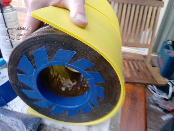
Hey Tony, with the issue of the wire being close to the torroid, could some layers of coreflute built up on the outside before winding help like this?
This stuff is meant to retain it's integrity till 85c.
.Cheers Caveman Mark Off grid eastern Melb
Warpspeed Guru Joined: 09/08/2007 Location: AustraliaPosts: 4406
Posted: 02:29am 20 Oct 2019
Copy link to clipboard
Print this post
It should help a lot.
Try wrapping it around the outside exactly as you have in the picture, and cut out a couple of discs of similar material for top and bottom. Nothing can be done around the inside of the hole without making the hole far too small.
I have no idea of how bad this capacitance problem actually is, Klaus seems to have vanished from the scene, and I don't really have anything here to do any realistic testing with myself.
There is no requirement for the wire to closely hug the steel toroid. Each pass through the hole counts as one full turn, no matter where in the hole it is located.
The other three quarters of each turn around the outside of the toroid, really contributes nothing except return the wire back into position for another pass through the hole.
Only slight disadvantage of doing this, is the length of each turn will increase slightly, but the effect of that is not going to be very great.
I am a bit stuck at the moment. My good Tektronix oscilloscope is not working. All of the calibration constants are held in a battery backed ram which has failed. Its not the battery that has died but the ram. I ordered another ram chip from China which did not work (bastards). So will have to order again locally before I can really do anything. Even then, I need to go through a very long and detailed re-calibration routine which looks fairly difficult as I will have to build a very accurate voltage and frequency calibration box..
In desperation I just ordered a brand new Rigol DS1054Z oscilloscope which is not going to arrive until next month. I can still see images on my cro, but have no idea of what the sweep speed or amplitude is I am looking at, as the on screen digital readouts no longer work, and the front panel knobs have no calibration marks.Cheers, ĀTony.
Solar Mike Guru Joined: 08/02/2015 Location: New ZealandPosts: 1123
Posted: 02:37am 20 Oct 2019
Copy link to clipboard
Print this post
Hi Tony, I have quite a few cmos ram chips floating around here, that used to be in old microbee computers with battery backed dc to hold the memory.
What is the chip, I may have some.
Cheers Mike
Warpspeed Guru Joined: 09/08/2007 Location: AustraliaPosts: 4406
Posted: 02:59am 20 Oct 2019
Copy link to clipboard
Print this post
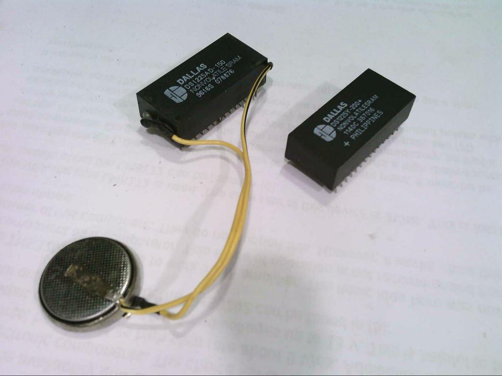
Its one of those Dallas battery backed rams with the built in battery DS1225.
What is really interesting, is that the original Tektronix Dallas part has a large external 3v lithium cell dangling from it, which is still at fully +3v. I have never seen a Dallas chip like that before. Ā The Chinese replacement is the much more usual fully self contained black block, with the ten year rated battery inside. The Chinese one has some random data inside that I can read, but not write to, so its useless. Its also 200nS where the original was 150nS speed rated.
The DS1225 is 8K x 8 and the pinout equivalent of a 28C64 ram or 27C64 eprom. I will probably burn an eprom for it once I get it going again, so the battery will no longer be a problem that can ever return.
All this might take some time, as I am working through a few other problems at the moment like car trouble and blocked drains. Edited 2019-10-20 13:48 by WarpspeedCheers, ĀTony.
renewableMark Guru Joined: 09/12/2017 Location: AustraliaPosts: 1678
Posted: 04:10am 20 Oct 2019
Copy link to clipboard
Print this post
I can't help with the dso, but sing out if you need help with the car.
Don't know how feasible it would be, but how about wrapping the primary on first, then the secondary? Would that help with the capacitance issue?Cheers Caveman Mark Off grid eastern Melb
poida Guru Joined: 02/02/2017 Location: AustraliaPosts: 1388
Posted: 04:47am 20 Oct 2019
Copy link to clipboard
Print this post
This looks just like my build quality. It's done already, perfect. Draw a line under it and it's time for a beer.wronger than a phone book full of wrong phone numbers
Warpspeed Guru Joined: 09/08/2007 Location: AustraliaPosts: 4406
Posted: 05:00am 20 Oct 2019
Copy link to clipboard
Print this post
Its always going to be neater and much easier to wind if the thinner wire goes on first, and the lumpiest winding with fewer turns goes on last. Primary or secondary does not change that. The higher voltage winding always goes on first for the neatest result.
I cannot see that would really help us with this problem. A toroid is the very worst way to wind a high frequency transformer where there are a very large number of turns and the core is highly conductive material (like steel). Much lower capacitance will result with ferrite or something much less electrically conductive.
About the best we can do is provide some physical separation between the core and the higher voltage winding and whatever goes on top of it. That is half the problem.
The other half of the problem is the transformer step up ratio needed to drive the secondary. The greater the voltage step up ratio, the harder the primary will be to drive, requiring a higher current.
The first thing to do is make some measurements to get an idea of what is actually happening and the scale of the problem. Then work from there. I am pretty sure its only the largest transformer that is going to be a problem for us.
So we test the smallest inverter first, look for current spikes. If they are there at all they will be small. Then test the second inverter, and see how that goes. Then the third, and we might start seeing some current spikes that may or may not require steps to reduce the problem.
Don't really know for sure, this is a problem I have not had to deal with before. There are a few special winding techniques developed for reducing capacitance in high frequency transformers and coils, but none are really applicable to toroids.
Problem with the car is pretty straightforward, just a lot of work and annoying. But thanks for the offer of help its really appreciated.Cheers, ĀTony.
Warpspeed Guru Joined: 09/08/2007 Location: AustraliaPosts: 4406
Posted: 05:06am 20 Oct 2019
Copy link to clipboard
Print this post
Haha, like one of my software programs. If it runs its fine. Even if nobody including myself understands how.Cheers, ĀTony.
renewableMark Guru Joined: 09/12/2017 Location: AustraliaPosts: 1678
Posted: 05:15am 20 Oct 2019
Copy link to clipboard
Print this post
The primary on No1 needs 25 turns of 35mm2
I could do this with 1.8mm (2.5mm2) wire. So 14 windings of 25 turns. Terminate all the ends together and we have 35mm2.
Then put the secondary on as per usual. 4 windings of 128 turns. Edited 2019-10-20 15:16 by renewableMarkCheers Caveman Mark Off grid eastern Melb
renewableMark Guru Joined: 09/12/2017 Location: AustraliaPosts: 1678
Posted: 05:20am 20 Oct 2019
Copy link to clipboard
Print this post
I was thinking they could all be stacked up on top of each other with a couple of china dinner plates between them. They would be a nice non conductive heat sink between each one. Need to test if a hole saw will cut a hole in the middle for a rod to hold the big "pancake stack" together.Cheers Caveman Mark Off grid eastern Melb
Warpspeed Guru Joined: 09/08/2007 Location: AustraliaPosts: 4406
Posted: 06:02am 20 Oct 2019
Copy link to clipboard
Print this post
The hole is 100mm (circumference ~314mm), and 25 turns of 1.8mm will take up at least 50mm. So fitting on 14 individual windings is going to be messy with wires poking out all over the place.
A better solution IMHO might be to wrap a bunch of 14 strands around 25 times without twisting the wires together. Ā Start in the middle and wrap thirteen turns around just less than 180 degrees of the toroid one way, then the other twelve turns around the other half. That will produce a flatter winding with only two ends coming out in roughly the same place. Sort of looking like this:
Then add a super super super thick layer of insulation. And finally the high voltage secondary on last.
That would have the advantage of having nothing on top of the secondary, and that should reduce the capacitance significantly. Edited 2019-10-20 16:15 by WarpspeedCheers, ĀTony.