Notice. New forum software under development. It's going to miss a few functions and look a bit ugly for a while, but I'm working on it full time now as the old forum was too unstable. Couple days, all good. If you notice any issues, please contact me.
Warpspeed Guru Joined: 09/08/2007 Location: AustraliaPosts: 4406
Posted: 06:41am 01 Nov 2019
Copy link to clipboard
Print this post
The problem we are trying to solve is capacitance between the secondary and everything else. The primary is not really the problem.
The primary could have gone straight over the core. Sorry I did not make that point more clear. But if you have spaced that, it does not really matter.
Its definitely going to require another spacer between primary and secondary, which is much more important.
Its a really good idea putting the secondary on top for the largest toroid. The other toroids should work fine as they are.Cheers, ĀTony.
renewableMark Guru Joined: 09/12/2017 Location: AustraliaPosts: 1678
Posted: 09:08pm 02 Nov 2019
Copy link to clipboard
Print this post
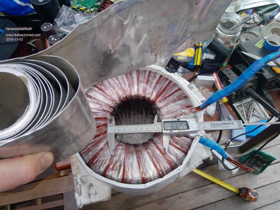
OK got the 14 windings of 25 turns all done for the primary.
Is it any use to put some aluminium between the layers of coreflute?
Also still stick with 2 sheets of coreflute?Cheers Caveman Mark Off grid eastern Melb
Warpspeed Guru Joined: 09/08/2007 Location: AustraliaPosts: 4406
Posted: 09:38pm 02 Nov 2019
Copy link to clipboard
Print this post
I really have no idea how important an electrostatic screen is for this. I asked for screens when my Warpverter transformeers were wound, but then it is dead easy to do with a E&I transformer.
Klaus fitted screens, not sure if Andrew did or not ?
If you are going to fit a screen, fit the screen right close over the primary with just some mylar tape for adequate insulation. No need for spacing that away from the primary.
The screen needs to be interrupted by having a break or slot right around the outside circumference, so that it cannot act as a shorted turn. Then bond a wire onto that.
Then fit two nice thick layers of coreflute over the screen, top, bottom, and around the outside (but not inside the hole).
An 80mm hole has an area of about 5,027 mm square.
Your four secondaries will be 4 x 128 turns x 2mm sq copper = 1,024 mm square of copper.
Usual rule of thumb, a "perfect" coil wound onto a rectangular bobbin with tight even layers and no insulation between layers can in practice reach about 60% fill factor of copper versus total available winding area.
You are not going to be able to reach anything like that on a toriod.
But the 20% fill factor you require to reach, should certainly be possible. Edited 2019-11-03 07:54 by WarpspeedCheers, ĀTony.
renewableMark Guru Joined: 09/12/2017 Location: AustraliaPosts: 1678
Posted: 10:11pm 02 Nov 2019
Copy link to clipboard
Print this post
I don't have any copper foil and you can't solder aluminium.
What I was thinking was to do a big washer top and bottom and one around the outside. If they overlap a bit just the pressure from the windings that will go over the top should create some kind of a connection.
The centre is running out of workable room already, probably only kitchen foil is all that would fit in there sensibly.
Now that I just wrote all that down it sounds pretty dodgy and a bit like a waste of time.Cheers Caveman Mark Off grid eastern Melb
Warpspeed Guru Joined: 09/08/2007 Location: AustraliaPosts: 4406
Posted: 10:38pm 02 Nov 2019
Copy link to clipboard
Print this post
Thinking about this......
The whole purpose of a screen is to eliminate the direct capacitive coupling between primary and secondary.
If we fit a big fat physical spacer between primary and secondary, that is going have pretty much the same effect as a metal screen anyway.
So i think all things considered, give the screen a miss.Cheers, ĀTony.
mackoffgrid Guru Joined: 13/03/2017 Location: AustraliaPosts: 460
Posted: 09:32am 04 Nov 2019
Copy link to clipboard
Print this post
Hi guys,
I left the original aerosharp screen on the transformer but I haven't connected it to anything - didn't even occur to me to try.
Cheers
Andrew
renewableMark Guru Joined: 09/12/2017 Location: AustraliaPosts: 1678
Posted: 10:55am 04 Nov 2019
Copy link to clipboard
Print this post
Now you have a new experiment to do.Cheers Caveman Mark Off grid eastern Melb
mackoffgrid Guru Joined: 13/03/2017 Location: AustraliaPosts: 460
Posted: 11:08am 04 Nov 2019
Copy link to clipboard
Print this post
except it's a 3 hour drive away
Warpspeed Guru Joined: 09/08/2007 Location: AustraliaPosts: 4406
Posted: 11:33pm 04 Nov 2019
Copy link to clipboard
Print this post
I hope to look at all this a lot more closely when my new oscilloscope arrives, and I can post some nice clear screen shots from it. Still waiting unfortunately.Cheers, ĀTony.
renewableMark Guru Joined: 09/12/2017 Location: AustraliaPosts: 1678
Posted: 07:56am 07 Nov 2019
Copy link to clipboard
Print this post
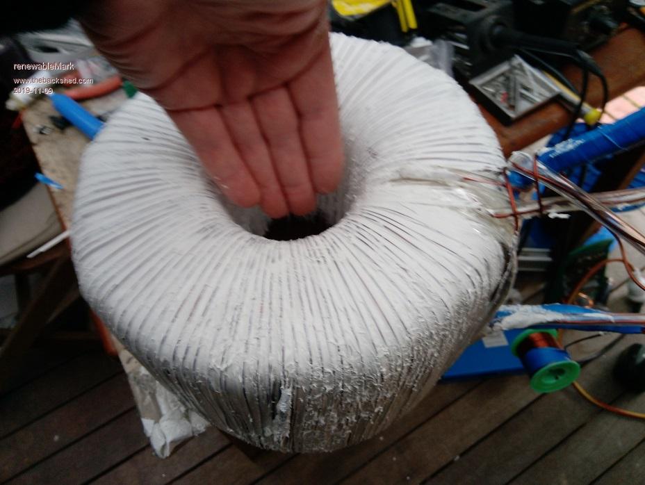
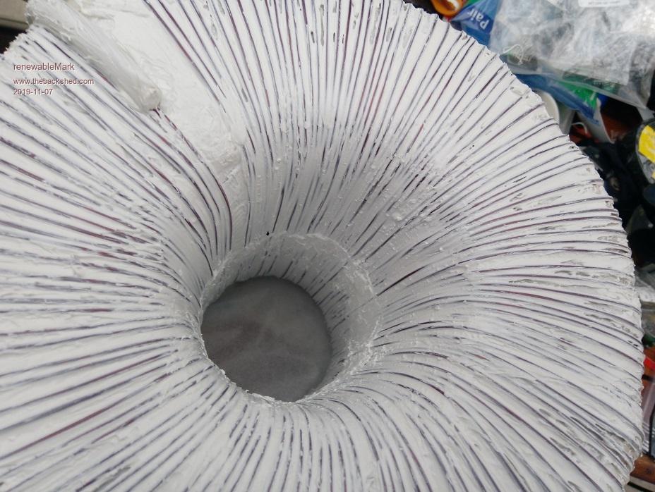
Got the padding on top,bottom and sides of 2 layers of the coreflute 3mm.
It got the first winding of the 4 secondaries on.
It took up almost all the circumference in the core, so the next three will need to be sealed and mylared before finishing the layer as they will have to overlap.
I'm not going to fit all 128 turns in one layer with the next 3 secondaries.
So in short, this torroid is going to be the biggest pain in the ass torroid I have done so far.
The bobbins have had to be reduced to, so more solder joins on each wind.
With any luck it will make a big improvement, good thing is I have the Std version already done so a good comparison can be made between the two.
BTW the white stuff is polyurethane that sets like rubber, I use this rather than epoxy.
. Edited 2019-11-07 17:58 by renewableMarkCheers Caveman Mark Off grid eastern Melb
mackoffgrid Guru Joined: 13/03/2017 Location: AustraliaPosts: 460
Posted: 07:41pm 07 Nov 2019
Copy link to clipboard
Print this post
Looking good Mark.
Speaking as a lazy tranformer winder, (I go to great lengths not to fully wind a transformer as you do - even to the point of hurting my arm )
If this helps Tony make usefull observations about Toroids it will benefit warpverters but will likely have a greater impact on SPWM inverters.
Cheers Andrew
renewableMark Guru Joined: 09/12/2017 Location: AustraliaPosts: 1678
Posted: 07:52pm 07 Nov 2019
Copy link to clipboard
Print this post
Never thought about that.
Can't test an SPWM with this torroid though, the primary turns are too different.
And this is my very last set of cores Edited 2019-11-08 05:55 by renewableMarkCheers Caveman Mark Off grid eastern Melb
Warpspeed Guru Joined: 09/08/2007 Location: AustraliaPosts: 4406
Posted: 08:01pm 07 Nov 2019
Copy link to clipboard
Print this post
Mark,
For testing purposes we can get away with having just one secondary layer. Extra layers on top will certainly add to the final power capability, but should have zero effect on the capacitance back down to the primary and to the the core.
So maybe give your fingers and your patience a rest for a while
New oscilloscope arrived late yesterday, and I spent the evening trying to learn how to drive it. By golly it has some complicated features, but today with "L" plates and training wheels I will take it for a spin around the block.Cheers, ĀTony.
renewableMark Guru Joined: 09/12/2017 Location: AustraliaPosts: 1678
Posted: 08:31pm 07 Nov 2019
Copy link to clipboard
Print this post
Ahh, having a new toy is always fun, like a kid with a new train set.
The Actual machine needs to be all wired up yet, haven't even started on that.
Did you just want to test the big torroid connected?Cheers Caveman Mark Off grid eastern Melb
Warpspeed Guru Joined: 09/08/2007 Location: AustraliaPosts: 4406
Posted: 09:26pm 07 Nov 2019
Copy link to clipboard
Print this post
I want to first of all try out a few different methods I have here of measuring the current in the primary with my new toy, I have several options.
Then make a few measurements on the transformers in my own inverter, plus test a toroid from an Inspire grid tie inverter.
First I need to figure out a convenient way to do all of this so we can test and compare just bare transformers. I may need to build some kind of special test box to do that, don't really know at this stage.Cheers, ĀTony.
Warpspeed Guru Joined: 09/08/2007 Location: AustraliaPosts: 4406
Posted: 11:38pm 07 Nov 2019
Copy link to clipboard
Print this post
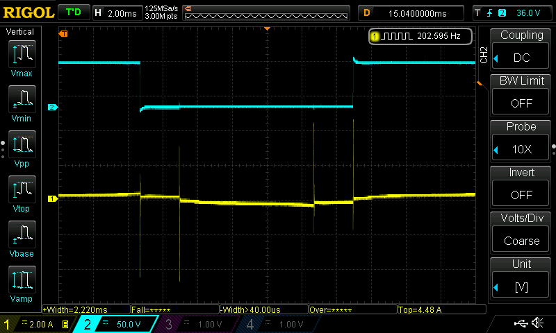
O/K I disconnected my Warpverter from its 100v battery and wheeled it over to my workbench, and connected it up to my rather small 60v dc bench power supply. I then connected a 100 amp current transformer in series with the primary of the largest inverter. Top blue trace is the voltage on one end of the primary. Yellow trace is current, the spikes are definitely there but only around 4.5 amps.
There is no load on the inverter output, my power supply is too small. The double spikes are the other side of the bridge switching, the blue voltage is only one side. With 100v on the inverter these spikes would be about 7.5 amps, still pretty small.
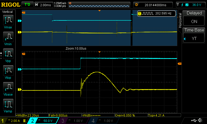
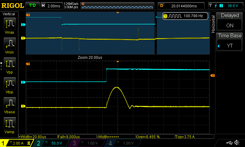
Here is one spike stretched out, it says 4.2 amps peak. The same thing again, this time with an LA55P 75 amp rated Hall sensor. This has a different scale factor of 50mV per amp, but basically shows exactly the same thing.
So no problem here. Andrew was measuring some 60 amp monster spikes.Cheers, ĀTony.
Warpspeed Guru Joined: 09/08/2007 Location: AustraliaPosts: 4406
Posted: 12:28am 08 Nov 2019
Copy link to clipboard
Print this post
Just had a look at the number two transformer spike. Under the same conditions its about an amp and a half.Cheers, ĀTony.
mackoffgrid Guru Joined: 13/03/2017 Location: AustraliaPosts: 460
Posted: 03:36am 08 Nov 2019
Copy link to clipboard
Print this post
In the first image, on the volts (blue) trace you can see the start of a capacitive spike with that little upturn on the leading edge. By magnitude it is nothing like I got.
The bottom image, yellow trace shows beautifully the charging of the capacitance. It would be nice to see the same shots with the inverter supplied by your battery.
Tony, how do you like the scope,
cheers Andrew
Warpspeed Guru Joined: 09/08/2007 Location: AustraliaPosts: 4406
Posted: 05:45am 08 Nov 2019
Copy link to clipboard
Print this post
I could turn the dc voltage up and down on my bench power supply, to only 60 volts max unfortunately, and the spike amplitude followed the voltage up and down in exact proportion as you would expect. Proportionally at 100v, the spikes would have probably reached about 7.5 amps. That is not a lot. It will draw that with only 750 watts of ac load on the inverter anyway.
A lower source impedance from the battery would have made no difference because the current for those spikes would all have all come from the three 12,000uF low esr electrolytics anyway.
The new CRO is magical, far more features than I ever expected. But because of that, it will take a lot more familiarity with it before I can get the most from it.
But very happy with it so far, highly recommended. Its only 50Mhz bandwidth but that is plenty for just about everything.
If I really do need more bandwidth for something very unusual, I still have my four channel 250Mhz analog Tektronix, once I fix the memory problem. The Rigol will help a lot with re-calibration of the Tektronix.
I will get back into that once we get Mark's Warpverter up and running.Cheers, ĀTony.
renewableMark Guru Joined: 09/12/2017 Location: AustraliaPosts: 1678
Posted: 04:35am 09 Nov 2019
Copy link to clipboard
Print this post
Started the second secondary. I got to 114 turns and it was clear 128 wasn't going to fit in one layer without overlapping, so pulled up stumps. Sealed it up, wait to dry, do the bottom, then mylar and finish the last windings to get to 128 turns.


 except it's a 3 hour drive away
 )
)