
|
|
Forum Index : Electronics : Stock Std Warpinverter
| Author | Message | ||||
renewableMark Guru Joined: 09/12/2017 Location: AustraliaPosts: 1678 |
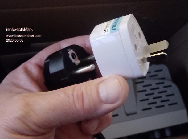 Dunno if they did it deliberately or out of cheapness, but it came with an international plug and adaptor. So no earth to worry about, just need to be aware of this. Cheers Caveman Mark Off grid eastern Melb |
||||
| Murphy's friend Guru Joined: 04/10/2019 Location: AustraliaPosts: 580 |
If I were you Mark I'd cut that black plug off and fit a proper Australian type. You can then also see if the unit has a 2 or 3 core mains cable. |
||||
| tinyt Guru Joined: 12/11/2017 Location: United StatesPosts: 430 |
Some scopes, mostly the older ones have the probe grounds connected to the the earth ground of the power plug. If you are going to use it on a non-isolated mains connected equipment, you can blow the equipment, the scope or both at first application of power. I am speaking from experience. So, for a mains powered scope I always make sure that the earth ground pin of the power plug is cut. Edited 2020-03-07 02:41 by tinyt |
||||
| Warpspeed Guru Joined: 09/08/2007 Location: AustraliaPosts: 4406 |
I agree. For most things a proper ground connection is a vital safety feature to prevent exposed metal parts from becoming alive if the internal mains insulation breaks down. Since the new age of fully plastic products, its now common to not have any exposed metal parts on many mains powered products, so there is nothing that needs to be grounded. There is nothing at all wrong with a two pin mains plug without ground pin. Now your spiffy new plastic oscilloscope has very few exposed metal parts you can come in full contact with, so its not going to be terribly dangerous even if it does become alive electrically. On the other hand, grounding it, also earths the probe grounds, which can cause no end of problems and potential destruction. Grounding exposed metal is definitely the safest thing, but electrical test equipment is a rather special case. Poking around inside high voltage equipment with test probes and ground clips is potentially dangerous anyway, but at least you are, or should be aware of the dangers involved. That is a very different thing to one of your children or your wife being electrocuted by a faulty household appliance that MUST be safely grounded. Cheers, ĀTony. |
||||
| renewableMark Guru Joined: 09/12/2017 Location: AustraliaPosts: 1678 |
When I got the old analogue cro, I pulled the plug apart to disconnect the earth, but a previous owner had already done it. Cheers Caveman Mark Off grid eastern Melb |
||||
| Warpspeed Guru Joined: 09/08/2007 Location: AustraliaPosts: 4406 |
Its sometimes very useful to be able to measure things that are not ground referenced. Upper mosfet gate drivers for example ! A much better and safer way would be to use an isolated probe, and leave the main oscilloscope grounded. One interesting older piece of equipment I have been looking at is the Tektronix A6902A. This provides two fully isolated floating measurement channels as a "front end" that plugs into your two channel oscilloscope. Good for 20 Mhz and 3Kv of isolation. These are more or less readily available on the secondhand equipment market, but make sure you get the special probes with it. http://w140.com/tekwiki/wiki/A6902 Cheers, ĀTony. |
||||
| renewableMark Guru Joined: 09/12/2017 Location: AustraliaPosts: 1678 |
Had a busy weekend with the family, so still haven't used the scope. I got the control board and a 12v supply mounted to a sheet of perspex. Just need a fuse for that, then mount the resistors to feed the bus bars with a restricted supply and I can start testing the torroids. So with the big No1 I have 2 identical sets of double stacked 3 Kw cores. One was wound the conventional way with the secondary on first and large primary wire over the top. Second one has multiple thin primary wires wound first all joined together to match the same mm2, then a 6mm spacer on top of that, then the secondary windings went on last. It will be interesting to see the differences between the two winding methods. Bad news is I have lots of work on and may not get to it for a while. 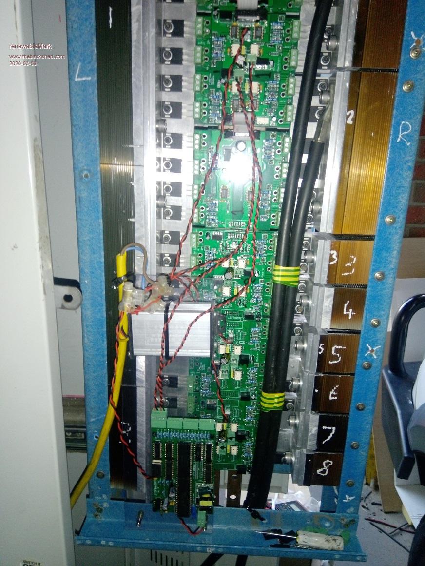 Cheers Caveman Mark Off grid eastern Melb |
||||
| renewableMark Guru Joined: 09/12/2017 Location: AustraliaPosts: 1678 |
Tony how have you found those bilge blowers, I'm thinking they may be suitable for this setup, one at the bottom of each heat sink stack. The 130cfm are 2.5A, it would need one each side, so 60 watts. I have no idea what 130cfm feels like though would that be enough? Don't want to go too big as the torroids will need a fan too. Edited 2020-03-09 19:52 by renewableMark Cheers Caveman Mark Off grid eastern Melb |
||||
| Warpspeed Guru Joined: 09/08/2007 Location: AustraliaPosts: 4406 |
The bilge blower I bought from e-bay is rated for 270CFM at 12v and 6 amps free airflow. I actually measured almost exactly 300 CFM free airflow with 14v applied. That is quite a lot of air. If you are planning on using two, the smaller 130 CFM size may be enough, difficult to judge. That inverter is so huge, its going to heat up very slowly. At least initially it will do rather a lot without any fans at all. I might suggest you get it going first, then judge how much help it really needs with forced air cooling. I think you are going to be surprised how cool it runs, even with no fans. Cheers, ĀTony. |
||||
| renewableMark Guru Joined: 09/12/2017 Location: AustraliaPosts: 1678 |
Currently the nanoverter copes with the loads put on it with 2x 120mm fans that push around 40cfm each (one for heat sinks and one for torroid). But on really hot days (40c or more) with both air cons running in the house, the torroid side keeps rising in temp, and needs another fan turned on, (that just gets put on manually for the whole day). Funny thing is the heat sinks never need more than one 120mm fan for both left and right heat sinks. So given the heatinks in the new one are 3 times the size and will cop the same loads it should probably be just fine with one fan on each heat sink, which is twice what the nanoverter has. If that's all that's needed it would be great as they are very quiet and only draw 5 watts each. Running 4 torroids with square waves will be interesting to see how they react compared to one single spwm. Cheers Caveman Mark Off grid eastern Melb |
||||
| Warpspeed Guru Joined: 09/08/2007 Location: AustraliaPosts: 4406 |
Should not make any difference. The current through all of the series connected toroids will be a nice clean 50Hz sine wave. The voltages will be square waves of a whole bunch of different frequencies in each toroid. A real dog's breakfast of square waves. But its the current that generates the heat in the wire, not the voltage. So heat wise, it should not be any different to any other pure sine wave inverter. Cheers, ĀTony. |
||||
| renewableMark Guru Joined: 09/12/2017 Location: AustraliaPosts: 1678 |
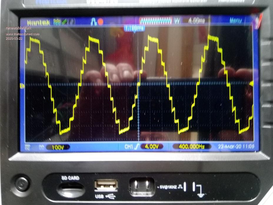
Finally started testing. This was initially done with restricted power to see if anything was out of the ordinary. Then full power was applied but still no caps fitted. The wave seems to have spikes at the edges which grow from one set of steps, then swap to the next set of steps and grow there. This was done with the large torroid and it's matching driver. 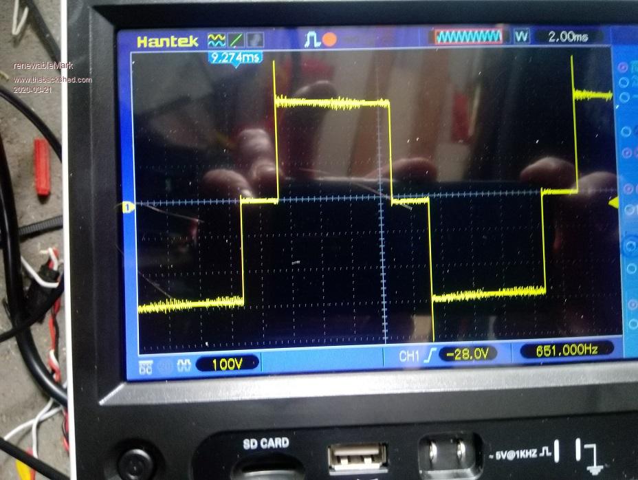 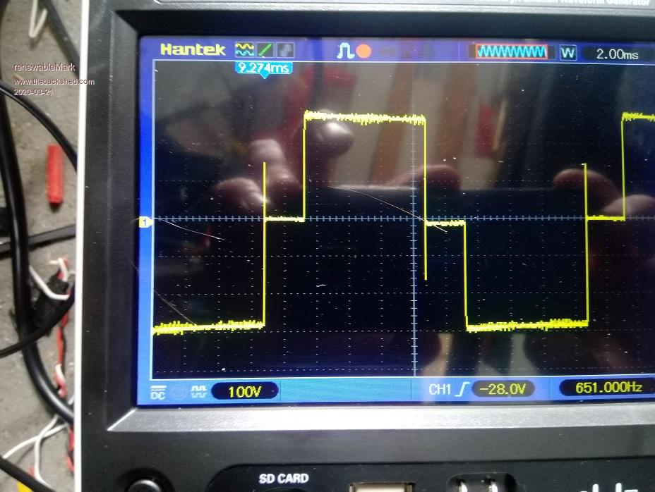 Cheers Caveman Mark Off grid eastern Melb |
||||
| renewableMark Guru Joined: 09/12/2017 Location: AustraliaPosts: 1678 |
Just did the same test with the large driver connection sending signals to the no 2 power board and got the same result ( so I know the two different power boards and control cards work the same) Cheers Caveman Mark Off grid eastern Melb |
||||
| Warpspeed Guru Joined: 09/08/2007 Location: AustraliaPosts: 4406 |
Hi Mark, my internet connection took a complete dump Friday night, and has only now started working again. That all looks fine. You will very likely see those same spikes on the main dc supply, they will go away when the big electrolytics are connected back up. Keep going and bring the smaller two inverters to life. The combined waveforms on the secondaries may look a bit odd too, at this very early stage. There will be a lot of power circulating around between the various inverters, and without a stiff dc power source to work from, everything gets a bit chaotic, but it will all come together perfectly once everything is finally all working together. Cheers, ĀTony. |
||||
| renewableMark Guru Joined: 09/12/2017 Location: AustraliaPosts: 1678 |
Before I go any further I might try the other torroid that got wound the traditional way to see how it compares on the same setup. Will it show any difference with the caps not in place though? Cheers Caveman Mark Off grid eastern Melb |
||||
| Warpspeed Guru Joined: 09/08/2007 Location: AustraliaPosts: 4406 |
I don't think you can really tell anything yet, except its working as it should, from a soft dc supply, without any dramas. Those voltage spikes occur when a diagonal pair of mosfets turn off, its a back EMF effect in the primary that has very little actual energy. Either placing some load across the secondary, or an electrolytic across the dc supply should get rid of them. Nothing to worry about, when everything is finally hooked up, they will be gone. The current spikes in the primary are a different thing entirely. They occur when a diagonal pair of mosfets turn on. The sudden instantaneous voltage step has to charge up all the capacitance across the transformer secondary. Your new "low capacitance" large toroid should go a very long way to minimising that problem. ĀWe shall see. Edited 2020-03-22 06:51 by Warpspeed Cheers, ĀTony. |
||||
| renewableMark Guru Joined: 09/12/2017 Location: AustraliaPosts: 1678 |
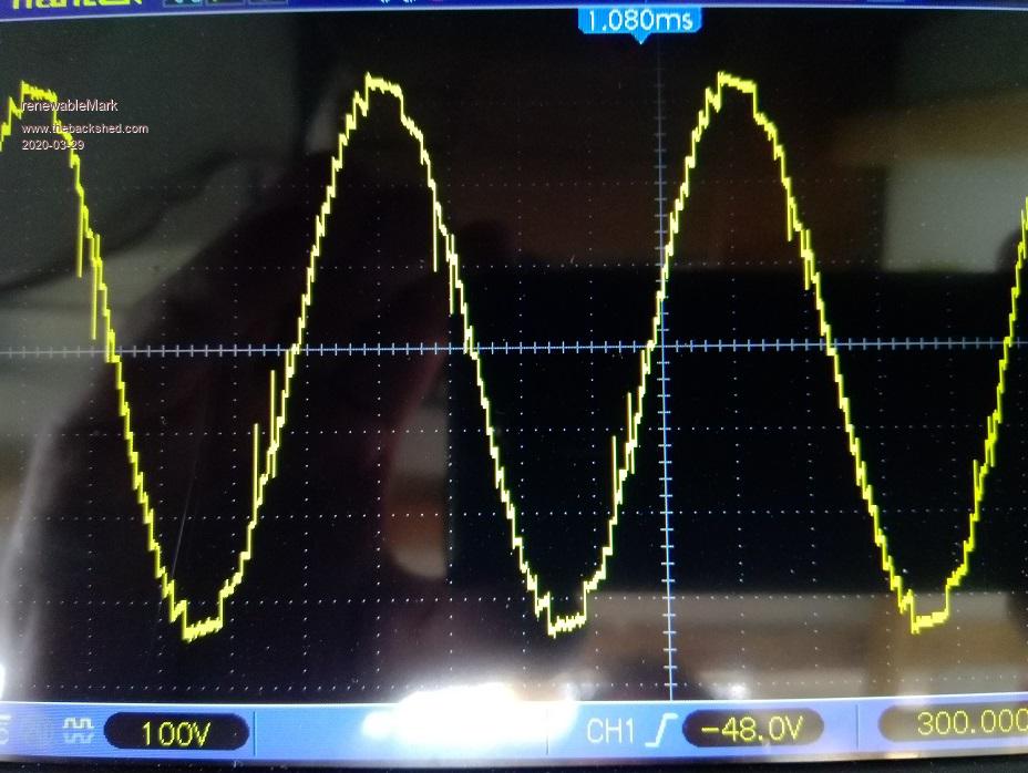
 Here it is with 1&2 in series. I'll wire up No 3 next. Cheers Caveman Mark Off grid eastern Melb |
||||
| Warpspeed Guru Joined: 09/08/2007 Location: AustraliaPosts: 4406 |
Excellent Mark ! Three in series will still look a bit rough and lumpy, but the sine wave shape begins to emerge. Each additional inverter makes a tremendous difference. When you connect up the smallest fourth inverter magic happens. This is mine with three inverters. 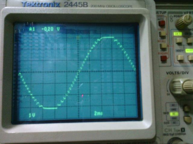 This is Andrew's with three inverters. If yours looks like those you are in for a very pleasant surprise when the fourth inverter is connected. I have no idea why it does that. Edited 2020-03-22 13:39 by Warpspeed Cheers, ĀTony. |
||||
| renewableMark Guru Joined: 09/12/2017 Location: AustraliaPosts: 1678 |
 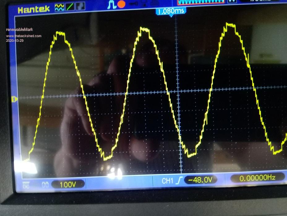 This is it with 3 largest in series. A few spikes appear at random times. Cheers Caveman Mark Off grid eastern Melb |
||||
| Warpspeed Guru Joined: 09/08/2007 Location: AustraliaPosts: 4406 |
Don't know where those spikes are coming from, some of them appear to be in the middle of a step. But otherwise, it looks o/k, it now shows the beginnings of a sine wave. Those spikes may have to do with grounding or lack of grounding on your oscilloscope, right now the whole mess is just floating, and there is rather a lot going on around your four transformers and all the associated wiring. The real test will be with number four going. That should clean it right up, especially after you tie one side of the 230v inverter output down to neutral/ground. Cheers, ĀTony. |
||||
