
|
|
Forum Index : Electronics : Stock Std Warpinverter
| Author | Message | ||||
| johnmc Senior Member Joined: 21/01/2011 Location: AustraliaPosts: 282 |
On a lighter note, when reading Warpspeed's comment "They grow old... Small electrolytics dry out and become leaky. Dry joints that worked for years start to act up. Potentiometers become noisy or worn out. Switches wear out and become intermittent, as do some plug in connectors. Rust and corrosion can appear on the circuit boards and metalwork. Knobs and controls break or get lost. That is the very old analog equipment typically thirty years old plus." It sounds like me at 78 plus years.  cheers john johnmc |
||||
| Warpspeed Guru Joined: 09/08/2007 Location: AustraliaPosts: 4406 |
I am only a very few short years behind you John. Cheers, �Tony. |
||||
renewableMark Guru Joined: 09/12/2017 Location: AustraliaPosts: 1678 |
It did bring back the trace to the full screen, but it's wavy with spikes in it. 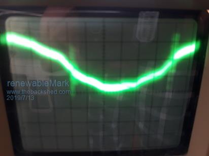 So something else is stuffed. 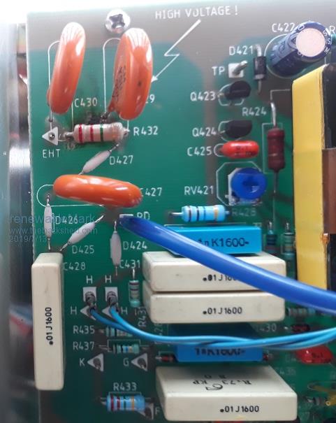 Probably that D427 which is a BY409 diode. But hell, where could it finish, could be chasing my tail for weeks and end up with the same busted bit of 30 Y/O crap. Cheers Caveman Mark Off grid eastern Melb |
||||
| Warpspeed Guru Joined: 09/08/2007 Location: AustraliaPosts: 4406 |
Very difficult to tell from a photograph what that really looks like. Cheers, �Tony. |
||||
| BenandAmber Guru Joined: 16/02/2019 Location: United StatesPosts: 961 |
Every time one of you guys put your age on here I think of how horrible it's going to be to lose all of that knowledge one day Good thing there's people like Kent getting into this kind of stuff I really hope you guys take him under your wing I think he's going to be a great like you guys one day be warned i am good parrot but Dumber than a box of rocks |
||||
| renewableMark Guru Joined: 09/12/2017 Location: AustraliaPosts: 1678 |
OK got a bit distracted with the busted CRO, back to the inverter. I decided to go with Mack's design of boards, took me a while to understand how it all goes together. So I have two options of how many power boards to do Option 1 Big toroid uses 3 power boards with one full bridge driver and 2 half drivers, 24 fets Med toroid uses 2 power boards with 2 half driver boards,16 fets Small torroid uses one power board with 1 full driver board, 8 fets Tiny toroid uses 1 power board with 1 full driver board, 4 fets Option 2 Big toroid uses 3 power boards with one full bridge driver and 2 half drivers, 24 fets Med torroid uses one power board with 1 full driver board, 8 fets Small torroid uses one power board with 1 full driver board, 4 fets Tiny toroid uses 1 power board with 1 full driver board, 4 fets I'm thinking my usual peak doesn't get over 5Kw so option 2 will do just fine. 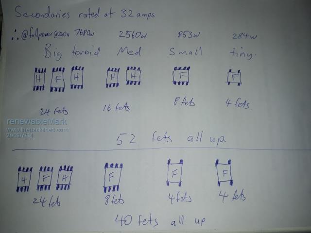 These are Mack's boards he has kindly shared with us all. 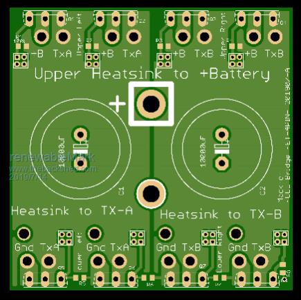 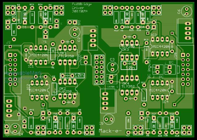 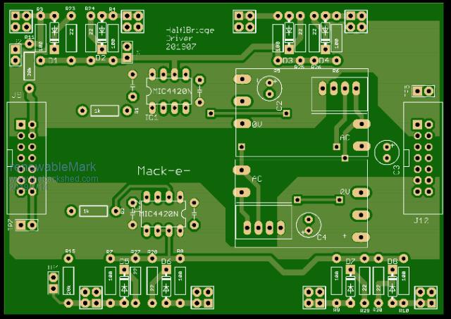 So the idea is to mount all this on some fibreglass channel vertically so natural cooling will help. That will hopefully fit in a school locker I have and will also have a nice small footprint. Cheers Caveman Mark Off grid eastern Melb |
||||
mackoffgrid Guru Joined: 13/03/2017 Location: AustraliaPosts: 460 |
Your option 2 is exactly what I have done with the 26v inverter. The power of the medium transformer is 33% of the large Transformer so the loading is shared pretty well. So it is fitting the second transformer is serviced by 8 mosfets when the large transformer is serviced by 24. Cheers Andrew |
||||
| renewableMark Guru Joined: 09/12/2017 Location: AustraliaPosts: 1678 |
Here are the drive signals 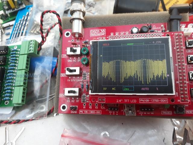 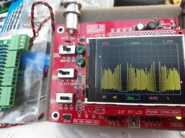 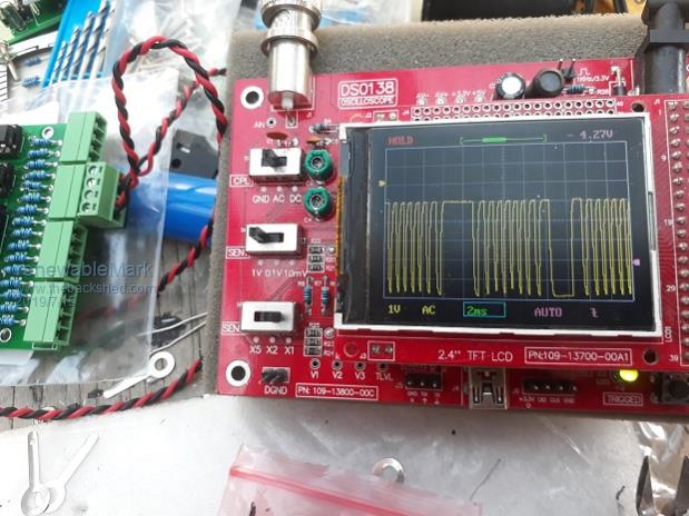 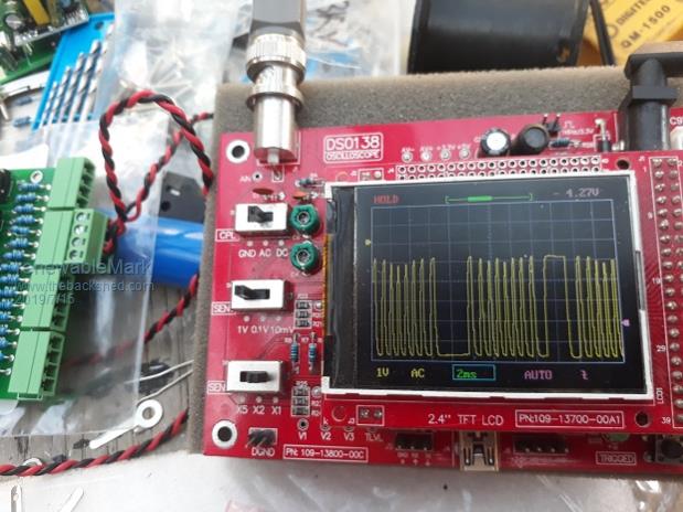 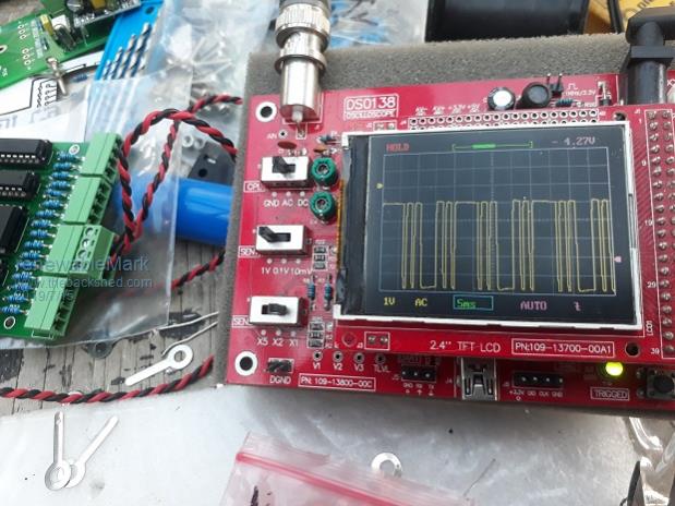 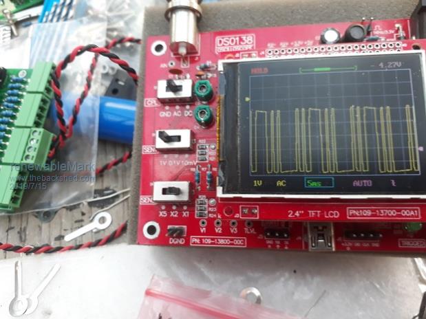 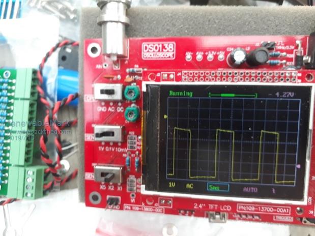 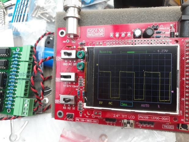 They all look OK to me. Since I have the small Warp driver/fet boards made I was thinking they could still be used for the two small torroids and with the big torroids the Mack boards could be used. Like this 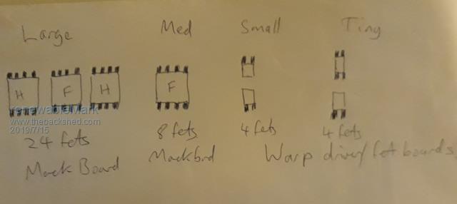 Cheers Caveman Mark Off grid eastern Melb |
||||
| Warpspeed Guru Joined: 09/08/2007 Location: AustraliaPosts: 4406 |
Those waveforms all look perfect Mark. Four of those small half bridge boards work just fine in my own two smaller inverters. It only starts to become a bit more complicated when you need to run multiple mosfets in each leg. Cheers, �Tony. |
||||
| renewableMark Guru Joined: 09/12/2017 Location: AustraliaPosts: 1678 |
I was thinking more of the compatibility of the Mack driver boards and the Warp ones used in one unit. On your Warp unit you have 8 identical driver boards. 4 drive small fets. 4 drive the IGBT's What I propose to do is Warp control board driving 4 Warpdriver/fet boards & 4 Mack driver/power boards. Will all the timing of the two different driver boards still work out? If I use the same dead timing cap they should match ok yeah? Cheers Caveman Mark Off grid eastern Melb |
||||
| Warpspeed Guru Joined: 09/08/2007 Location: AustraliaPosts: 4406 |
Its all compatible and all completely plug in interchangeable. No timing problems, its all very low frequency switching. Also Tinkers boards would work too. All use the exact same opto driver interface and plug pin connections so its plug and play. Andrew and I arranged it that way deliberately right from the beginning. Only thing that may need a bit of thought is the power supply to the isolated gate drivers. I take my power from directly across the dc supply to each bridge. That worked for me because my inverter is 100v. Some of those small postage stamp supplies will not start up and run reliably from a 48v battery that is very low, but others might be o/k. There seems to be a big variation depending where you buy those supplies. Both Klaus and Andrew have used a different way to power their boards, but otherwise they are completely compatible. Dead time is not critical 1nF to 10nF would cover the range (300nS to 2.5uS). Something about in the middle of that should work fine, say 2.2nF or 3.3nF for mosfets. Its only the big old and slow IGBTs that need 2.5uS. Cheers, �Tony. |
||||
| Warpspeed Guru Joined: 09/08/2007 Location: AustraliaPosts: 4406 |
Some further thoughts on those small power supplies.... They require a certain voltage to start up, but once running the voltage can drop a fair way before they stop working. I have tested a few of these, and startup can occur anywhere between about 32v and 45v. Now you would never start up an inverter with a heavy load already connected to it, you would normally soft start it up completely unloaded, then close the ac circuit breaker on the output once its running. Even with an almost flat battery, the battery voltage will be up a bit under no load starting conditions. Its only under really heavy load that the battery voltage gets pulled right down. So my thoughts are, that if those small supplies can start up cleanly with the inverter unloaded, and then switching on the load which pulled down the battery voltage, those supplies are very likely to keep running well below the start up voltage threshold. If you do a test to find out what is the startup up voltage, and what is the minimum running voltage where they drop out, it may well be that what you have right now will have sufficient margin not to be a problem. Cheers, �Tony. |
||||
| renewableMark Guru Joined: 09/12/2017 Location: AustraliaPosts: 1678 |
5th post down on this thread have the test results of the ones I got. Starting up with no load the battery will probably be 54v or higher. I didn't write down the dropout voltage, we did do it, I think it was like 40v or close to that. Cheers Caveman Mark Off grid eastern Melb |
||||
| renewableMark Guru Joined: 09/12/2017 Location: AustraliaPosts: 1678 |
I was stripping another 3kw toroid today and noticed the wire was a lot thicker. Put the micrometer on it and it was 2.01mm, then checked some other stuff, most was 1.8mm and some was 1.6mm diameter. Now question is, if that got mixed up on one torroid I wound would it make a difference? I'm thinking not as the turns are the important thing. I checked all the ends of my wound torroids they all matched. The 6kw one was all 1.6mm the rest were all 1.8mm. Cheers Caveman Mark Off grid eastern Melb |
||||
| Warpspeed Guru Joined: 09/08/2007 Location: AustraliaPosts: 4406 |
I doubt if you mixed up the wire. 2mm is visually thicker and much stiffer. Also it "looks" quite different once you have wound a few turns. With regard to those small dc power supplies, trying to work out what might be the worst case in theory, and what you can actually get away with in practice are two different things. If you don't have an adjustable voltage power supply to test with, try connecting a bare half bridge board (without its mosfets) across your battery, and then across a few cells less, until either of the red LEDS fail to come up to full brightness straight away. If the supply cannot start up and self sustain, those LEDs will pulse on and off. Then measure what that minimum start up voltage is, then you will know for sure. Cheers, �Tony. |
||||
| renewableMark Guru Joined: 09/12/2017 Location: AustraliaPosts: 1678 |
Yeah, well I certainly haven't had any 2mm slip into a rewind. That did stand out as much thicker. The 1.8 and 1.6 is hard to tell till you actually measure it. But would it make a difference? Cheers Caveman Mark Off grid eastern Melb |
||||
| Tinker Guru Joined: 07/11/2007 Location: AustraliaPosts: 1904 |
There is a difference with how many turns you can fit around the toroid hole. The bigger wire can carry more current obviously. I wound all my 4 secondaries with 3 x 1.7 (1.8?) wire. They should be the same on all 4 transformers as they carry the same load current. I would not worry too much if a 1.6 wire had slipped in at one of the parallel windings. Klaus |
||||
| Warpspeed Guru Joined: 09/08/2007 Location: AustraliaPosts: 4406 |
As Klaus says, once you start winding, going up or down a size for the next layer becomes very obvious. Even a small difference becomes cumulative and very noticeable. Cheers, �Tony. |
||||
| mackoffgrid Guru Joined: 13/03/2017 Location: AustraliaPosts: 460 |
Tony, What was that alternate part for the TLP250 / 3120 driver? |
||||
| renewableMark Guru Joined: 09/12/2017 Location: AustraliaPosts: 1678 |
This the one? data sheet BTW Andrew jlc took 4 days to make the boards, so not quite in time for dhl to get them to me by the weekend, should be here next week. Looking forward to working out the layout. Cheers Caveman Mark Off grid eastern Melb |
||||
