
|
|
Forum Index : Electronics : Little China inverter board, Hary�s build
| Author | Message | ||||
| Tinker Guru Joined: 07/11/2007 Location: AustraliaPosts: 1904 |
If you could take the time and look through past posts (use the search feature) you will find the choke saturation issue has been discussed here at great length. We even had a simple circuit for a saturation tester. I built one myself, it works very well but it also assumes a good knowledge of electronics. Also, it requires an oscilloscope, if you don't have one or can borrow one (and know how to use it) its no use to worry about choke saturation. Just use the details clockman provided, order that *particular* ferrite core and wind a choke. It will lower the idle current but most likely go into saturation with high loads. That seems to be no problem as I ran a power jack (8000 Chinese watts) module for a long time with just that choke in place before I upgraded to silicon steel flaked cores. This forum is a great resource so use it like a book, turn a few pages back to find your answers. Klaus |
||||
| hary Regular Member Joined: 15/04/2019 Location: FrancePosts: 89 |
Hi everyone. I think it's ready to fire it up !  It's quite a bit messy on the picture. But I think, I've done all that was recommended : - I made all Poida's modification on the power board.(removing over current protection an installed clamping TVS diode between source and gate of the power MOSFETs.) - I put the 47uH choke in series with the primer winding of the transformer - Installed that strange capacitor on the output of the transformer. I'll keep you informed about it but need to wait for the week end to take it to my remote place where I have my 24V battery. |
||||
| BenandAmber Guru Joined: 16/02/2019 Location: United StatesPosts: 961 |
I'm really glad you decided to use a choke that's an nice box you put it into Looks to me like you're going to be the first one to start one up without no smoke Beat it to death and come back and tell us all about it I think you're really going to like it be warned i am good parrot but Dumber than a box of rocks |
||||
| hary Regular Member Joined: 15/04/2019 Location: FrancePosts: 89 |
Hi everyone. It makes some light ! I finally fired the thing up and it works ! I was first afraid of the small noise growing up at the start, but it seemed it was the transformer's normal noise. I then plugged in a 60W bulb, I then tried the soup 100W soup mixer and it worked too. I then tried the small 110W fridge and everything stopped ! Even the inverter's small leds. I've blown up the 12A fuse. Of course, being chicken, I put that small fuse that didn't resist the fridge's big inrush current. Everything came back to normal when I replaced the fuse. I now wonder if there is a way to be sure not doing stupid things putting too big loads ? I mean how to find the limit of that stuff before blowing it up ? |
||||
| BenandAmber Guru Joined: 16/02/2019 Location: United StatesPosts: 961 |
My little one is 48 volts my Transformer is well over 25lbs and 1 volt per turn on the high side secondary And I have two 18000 UF capacitors I run a small air conditioner that pulls like 600 watts one or two box fans a few lights radio and then start my circle saw It does this without any problems at all So I would think you're board would handle it Either your Transformer ain't big enough or something else is going on If you can get one of the greats to comment on the situation you wouldn't have to guess the bigger the Transformer the better is what all the greats on here say be warned i am good parrot but Dumber than a box of rocks |
||||
| Tinker Guru Joined: 07/11/2007 Location: AustraliaPosts: 1904 |
First, tell us how much battery power (Ampere hours) you have available. I think you are running 24V? That will limit your load due high current. My rule of thumb is 1 real Watt = 4 Chinese Watts for endurance power ratings. I think that board has some current sensing on it. Klaus |
||||
| hary Regular Member Joined: 15/04/2019 Location: FrancePosts: 89 |
I have 8x160Ah LiFeYPO4, so yes, I'm on 24V. Then again, this first inverter is mostly a test and to run my 110W fridge. At the time, it's been running a small 60W water pump (universal motor) for about 5 hours. I'm waiting to try again on the fridge as it has a huge inrush demand. I need to redo the main supply cabling with short and proper thicker cable, so minimising the voltage droop and thus the even more bigger inrush current demand ! Yes B&A. But one of my biggest problem is to find the transformer ! I also wonder if I should had some bigger capacitor. The one installed, 2x2200uF, seems so little to me (Just feeling as I have neither experience, neither the necessary knowledge !) Again, I made the choice to go on 24V because the only proper BMS for my LiFeYPO4 battery that I find was in 24V. Plus my house run mainly on 24V, light, laptop, internet box ... As I already said, I only need the inverter for the fridge and my workshop tools. Of course I need much bigger inverter for the workshop, and I'm now facing the transformer's availability problem. As the inverter isn't meant to run 24h/day, I might try with EI core transformer. Talking with some other people that found a good low frequency inverter with toroid core transformer and 32W idle current might be an option. If I want to make one myself, only the cost of material might be higher than buying one already made ! |
||||
| hary Regular Member Joined: 15/04/2019 Location: FrancePosts: 89 |
Hi everyone. I've just done some proper short 16mm2 wiring to the inverter and tried to plug the fridge. But The inverter stops working. It needs to power down then power up again to start again. So it seems a security does activate. As the over current protection has been remove (as per Poida's advices), I guess it might be some undervoltage disconnect. The surprising things is that it needs a power cycle to restart. But anyway, what do you think that can cause the shutoff of the inverter ? There are 4 pots to be adjusted but I don't know which one act for as the naming is very strange ? Anyone of you have an idea ? |
||||
| hary Regular Member Joined: 15/04/2019 Location: FrancePosts: 89 |
I've just have the idea to try again doing some measurement with my clamp ammeter and some other motor. And it's unbelievable ! I've tried a small high pressure cleaner and before the inverter stopped, it went up to 90A (max function used) @26V, so that means 2340VA Again, as the overcurrent protection has been removed, I have no idea what cause it to stop. But 90A or 2340W is a lot ! As this was measured on the input DC side, there is no power factor involved, so the 2340W were actually eaten. To me, it was so much that I thought that energy wasn't all eaten in the motor but in the MOSFET as I think at that high current, my choke would definitely saturate and so do really bad things. But as I also have an old 12V 1250W high frequency inverter on a lead acid battery, I tried the same motor on that inverter. And the max current was .... 196A @12V, so 2350W, so considering the supposed old 12V lead acid battery droop voltage, almost the same as with the little chinese board inverter ! So I'm quite impressed and afraid with all these high amps ! Is the 1000W 24V little Chinese power board for 1000W continuous or surge ? |
||||
| BenandAmber Guru Joined: 16/02/2019 Location: United StatesPosts: 961 |
I'm here to say if you get a bigger Transformer that little inverter will do amazing things. Not sure but I think it was the adjustment to the left of the board the one closest to the heat sink be warned i am good parrot but Dumber than a box of rocks |
||||
| poida Guru Joined: 02/02/2017 Location: AustraliaPosts: 1388 |
There is DC supply under voltage limiting, as well as (maybe?) DC over voltage limit. I suspect it might have tripped when the battery supply as seen at the DC LV sample point on the board, dropped too low and caused it to trip. wronger than a phone book full of wrong phone numbers |
||||
| poida Guru Joined: 02/02/2017 Location: AustraliaPosts: 1388 |
4 pots means DC LV cutoff, AC output voltage, and likely a slow acting over current limit and a fast or peak sensing over current control. Here is a circuit of something similar, but not your particular board. 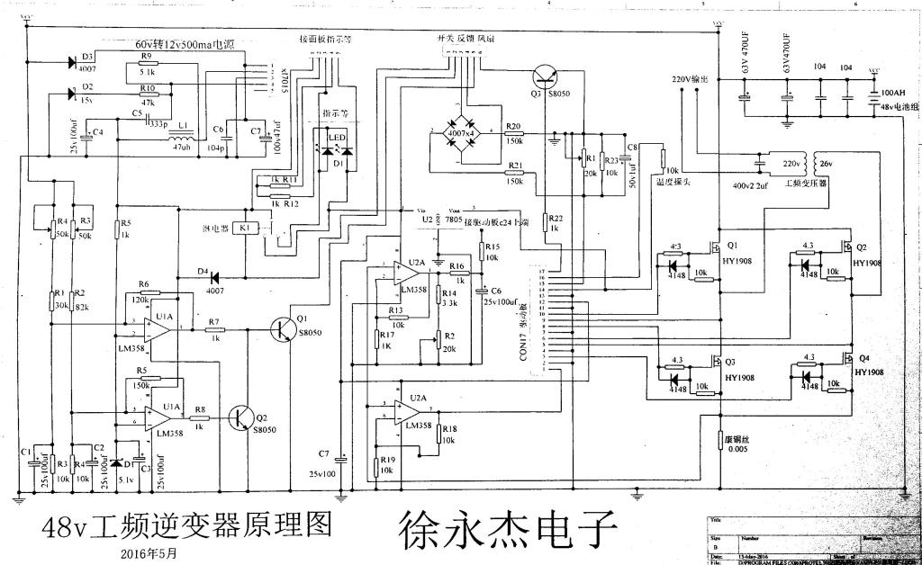 wronger than a phone book full of wrong phone numbers |
||||
| hary Regular Member Joined: 15/04/2019 Location: FrancePosts: 89 |
Yes, but as I already explained, I don't know where to find some. Plus the main problem seems to be the inrush current. Otherwise, I would need this inverter only for 110W, so less than 5A on the input DC side compared to the huge 90A inrush current for few second only. powerJack LF inverter are,to what I understand, not so bad about that point of the design ! High peak power capability and poor continuous power. I wonder If I should keep going and try to adjust that DC LV disconnect. I mostly afraid about my choke's ability at this insane inrush current. By the way, I noticed that induction motor are way more difficult to start than universal motor (at the same rated power) |
||||
| Solar Mike Guru Joined: 08/02/2015 Location: New ZealandPosts: 1123 |
This seller has the pots identified, scroll down the page for the description. Link Mike |
||||
| hary Regular Member Joined: 15/04/2019 Location: FrancePosts: 89 |
The only picture (or drawing) with pots identified are in Chinese hand writing ! No way I can understand that ! Sorry !  |
||||
| Solar Mike Guru Joined: 08/02/2015 Location: New ZealandPosts: 1123 |
You didnt scroll down the page far enough, see, shows circuit board with pots and their purpose written in English..... 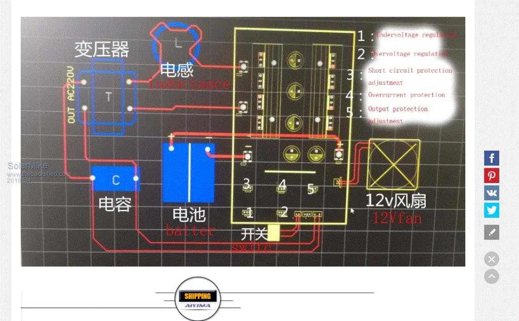  |
||||
| hary Regular Member Joined: 15/04/2019 Location: FrancePosts: 89 |
Mmmm ! I don't think this image has something to do with the board sold on the same link ! neither with mine despite I can confirm I've got the same board. If you look at the board, you'll see all the pots are dispatched all other the board. Not in the same place like on the image you reference. |
||||
| BenandAmber Guru Joined: 16/02/2019 Location: United StatesPosts: 961 |
I start loads with my little inverter that and 3000 watt power jack cant begin to start I actually think I would put it side-by-side and outdo the 6000-watt Power Jack The ones they sell in the United States only have one Transformer I have seen pictures of 6000 watt units with two Transformers they probably do a pretty good job The 8000 watt power jack my wife bought here a while back Warpspeed said the Transformer was good for about 1800 watts And if warpspeed says that you can take it to the bank be warned i am good parrot but Dumber than a box of rocks |
||||
