
|
|
Forum Index : Microcontroller and PC projects : aquisition speed
| Author | Message | ||||
| Volhout Guru Joined: 05/03/2018 Location: NetherlandsPosts: 5999 |
I do a lot of debugging of electronics hardware in my job. I always loved the simplicity of finding faults with in circuit curve tracing tools like the huntron tracker. The tracker is a signal generator that outputs some +20V/-20V sine wave or triangle wave form at 50Hz or so. That signal is applied to the circuit under test through a resistor (i.e. 10k) and the current is measured and displayed on a CRT (yes...it's that old). Defective pins on chips, or defective semiconductors, or defective capacitors have their distinctive signature (read: waveform). And when you can change the frequency and amplitude of the signal your debugging get's better. Especially when you can compare to a good working unit, the tool is perfect. Initially I thought this would be a nice tool to create around a MX170 LCD backpack. Best way to do this is create a X-Y display (i.e. 240x240 pixels) and have some controls in the remainder of the window. However...the backpack has only one analog input left (pin 24). The rest is dedicated to the LCD and touch. The one analog input must be used to measure the current (Y axis) The X axis can be generated using a DAC (actually I am trying to use the PWM at high frequency, and need to design a adequate analog filter). Please see below program that represents the acquisition core. I generate an array with values for the PWM (so I don't need extra calculations during the scan). In stead of erasing the screen previous to a new scan, I draw a black vertical line at that X location. That gives less screen flicker, and actually is just as fast. But... I get a refresh rate of 4 per second. The triangle frequency is about 8Hz (the scan takes just as much time as the display update). Can someone suggest a way to speed this up ? I saw there was a fast sampling and display (scope) cfunction that refreshes at 20 frames per second. But this function did not include X-Y mode or so. Rem curve tracer type huntron tracker Rem for LCD backpack on 28 pin MX170 Rem uses pin 24 as analog input Rem uses pin 4 as pwm output Option explicit init: Rem for maximum speed, highest clockfrequency CPU 48 Rem set io pins SetPin 24,AIN PWM 1,100000,50 Rem init variables Dim integer i,d(240) Dim float a(240),k Rem vertical scaling 3.3V to 240 pixels k=240/3.3 Rem initialize triange waveform For i=1 To 120 d(i)=i/1.2 Next i For i=121 To 240 d(i)=(240-i)/1.2 Next i Timer = 0 main: Rem scan through 1 complete waveform For i= 1 To 240 PWM 1,100000,d(i) a(i)=Pin(24) Next i Rem display For i=1 To 240 Rem clear previous pixel Line i,0,i,240,,0 Rem draw new pixel Pixel i,a(i)*k Next i Rem debug Print Timer Timer=0 GoTo main Suggestions are welcome.... PicomiteVGA PETSCII ROBOTS |
||||
| isochronic Guru Joined: 21/01/2012 Location: AustraliaPosts: 689 |
just a thought - (I am assuming Pixel i,a(i)*k draws one pixel ) if you are only drawing one pixel per vertical, I guess it would be faster to save the old pixel and blank that instead of blanking the vertical each time (?) - I don't know specifically though. ed- I had the same problem using line vectors (in a different system). You can save the old values in an array, at each successive point you can blank the old vector before plotting the new one. It takes a little more memory obviously, but it worked ok. |
||||
| matherp Guru Joined: 11/12/2012 Location: United KingdomPosts: 11673 |
This would be a fantastic application for the Armmite F4. Ultra-fast LCD + in-built DAC that can be set to run any waveform in the background |
||||
| Volhout Guru Joined: 05/03/2018 Location: NetherlandsPosts: 5999 |
@chronic I tried that, but it is actually slower. You need 2 arrays. I will make an additional try with a single array and drawing while measuring. This will however slow down the waveform generation even more. @matherp I'll order a set. They are cheap enough to give it a go. Some idea's I will try out: 1/ I have the feeling that using the AIN is slower because there is the conversion from integer ADC value to a float that gives a voltage. And in my code I have to convert the float back to an integer (pixel location). It might save time if I could read the ADC register directly. 2/ I may be able to remove the PWM by using an analog integrator driven by a IO pin. For a triangle waveform that IO changes only at the peaks. PicomiteVGA PETSCII ROBOTS |
||||
| isochronic Guru Joined: 21/01/2012 Location: AustraliaPosts: 689 |
Using an AD output as an integer is good, you can divide by 4 with bit-shifting right, gives a result scaled to 256 very quickly. A good experiment would be, to leave out the line command and see how if it is then fast enough ? |
||||
| Paul_L Guru Joined: 03/03/2016 Location: United StatesPosts: 769 |
The first time I ran across this idea was about 1953. RCA published a tech note describing how to make a curve tracer using a slow scope with X-Y inputs, a 6 volt transformer and a single current limiting resistor. We had about 15 Huntron Trackers in the electronic shops at Pan Am back in the 1980s. X2AEW recently put together a nice video using a cheap modern scope to show what it can do. https://www.eevblog.com/forum/beginners/dirt-cheap-and-simple-scope-based-component-tester-curve-tracer/ Paul in NY |
||||
| isochronic Guru Joined: 21/01/2012 Location: AustraliaPosts: 689 |
Any news on the graphics ? |
||||
| Volhout Guru Joined: 05/03/2018 Location: NetherlandsPosts: 5999 |
@chronic, I managed to get all functionality in the LCD backpack. The refresh rate dropped to 4 (4 Hz). But it works, and can detect components. Currently building a +/-15V supply for the analog circuit (opamps) from 4V (LiPo battery). I am waiting for the Armmite F4 now, also because the fast LCD, but mainly because the second A/D channel...ģ. I made a mistake in my understanding how these things work. They measure voltage and current AT THE COMMPONENT (not at the generator). So you need 2 A/D channels to do it right. My current approach works but it can not show waveforms from 2'nd order or higher filters (the nice circular lisayous graphs) since the X-axis cannot go back (increased voltage from generator can cause decreasing voltage at component with 180 degrees phase shift). The correct approach would be to show a circular buffer with X-Y coordiantes. The length of the buffer would need to be minimal 100 segements (line draw versus pixel draw) to get the resolution, and the buffer length would be some figure for "persistence". Erase the last line segment, write the new line segment at that location, advance the pointer. Then the signal generated need not be synchronized (which fit's the Armmite F4 that can generate an autonomous signal on the DAC). Volhout I noticed that the backlight on my 2.8" 9341 LCD has degraded a lot. Even with a 39 ohm series resistor to +5V is is not very bright, where as the 2.4" 9341 display is bright with 470 ohms series resistor to 5V. Maybe I should get rid of the 2.8" display.....(it also has one defective white line, very anoying). PicomiteVGA PETSCII ROBOTS |
||||
| matherp Guru Joined: 11/12/2012 Location: United KingdomPosts: 11673 |
I'm playing with this on the Armmite F4 but I'm a bit confused about this. If my generator is a true voltage source and I know what it is generating and I measure the voltage at the component then I know the voltage drop across the resistor and hence the current so only one ADC needed - what am I missing. My test rig is a DC-DC converter generating 28V from a 5V input. I then use a BUF634 to rail split this and give a low impedance virtual ground. An AD822 opamp amplifies the DAC to give +/- 14V with respect to the virtual ground and I can then use this through a resistor to power the test component. The voltage at the component is also buffered with an opamp so that it can drive a voltage divider to the ADC input of the Micromite. I now know the voltage I'm generating and the voltage at the component and can plot these (or the calculated current). Code to generate a 50Hz triangle wave on the Armmite F4 is below, haven't added the plotting yet: Option explicit option default NONE dim float d(99),a(99) dim integer i setpin pa0,ain setpin pa1,ain for i=0 to 49 d(i)=i/50*3.0+0.15 next i for i=50 to 99 d(i)=(99-i)/50*3.0+0.15 next i sync 200,u 'set up a high res timer at 200 micro-seconds interval do for i=0 to 99 dac 1,d(i) a(i)=pin(pa0) sync 'wait for timer to expire next i loop The picture shows the generated triangle wave and the voltage that would be across the component by subtracting the two channels where the second channel is connected to the virtual ground. Note: both scope channels are needed as the virtual ground is different from the scope ground and bad things happen if you try and connect them  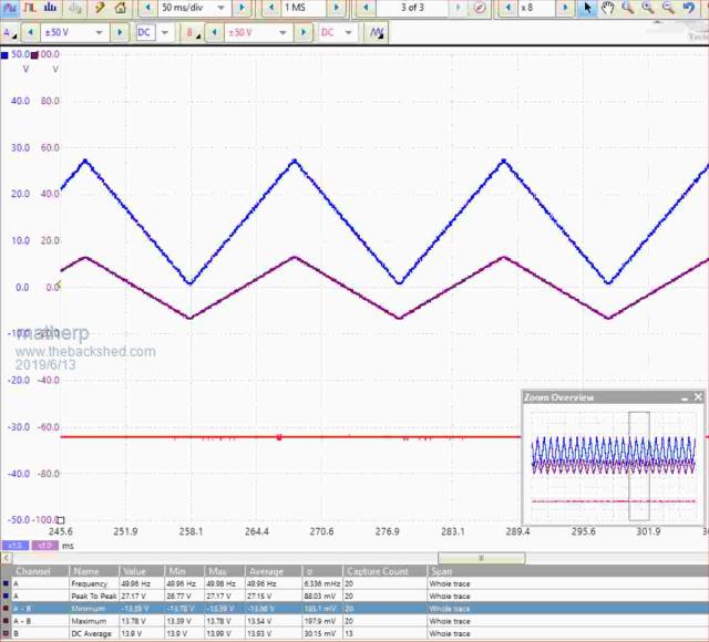 |
||||
| Volhout Guru Joined: 05/03/2018 Location: NetherlandsPosts: 5999 |
Dear matherp, If you check out Paul_L s post, or google octopus cicuit, that explains a lot. But to be honest, you are nearly there. The octopus circuit creates a floating sine wave from a transformer secondary winding. On side is fed to the component under test, this is signal A. The other side of the compinent is grounded. The other side of the winding, signal B, is connected to ground through a 47k resistor. A and B connect to a scope in XY mode. A represents voltage across the component. B the current ( voltage acros series resitor 47k). If i understand right your AD822 output is connected to a resistor, and then to the component under test. Other side of the component under test is at split rail. So signal A is simply the voltage at the component under test (a/d channel 1) Signal B is the differece between the AD822 output(a/d channel 2), and signal A. Simply subtract values to get B. You need to take into account that using a 47k resistor to determine a component characteristics, the measurement ciruit must be signifcantly higher impedance. This applies to signal A. The AD822 output is low impedance. I suggest a high impedance divider and then buffer in an opamp before going into the a/d. Something in the lines of 10 meg/1.2 meg that is roughly divide by 9, suiting the 3.3v range on the a/d. The opamp should be rail to rail. Now youve done what I wanted to do. Volhout. P.s. I wanted to create +\- 15 volt to make sure one pin of the component under test is at real gnd potential with respect to the USB ground. If something goes wrong in your split rail system currents can be high. PicomiteVGA PETSCII ROBOTS |
||||
| Warpspeed Guru Joined: 09/08/2007 Location: AustraliaPosts: 4406 |
I don't know if this will help, but I am putting together some hardware for someone else's project that uses a MCP3208 analog to digital converter. 100K samples/sec 12 bits and four differential input channels. https://www.datasheetspdf.com/pdf/439995/MicrochipTechnology/MCP3208/1 That would enable you to probe voltage and current displayed x/y on two channels, for comparing the same nodes between a good working circuit, and the faulty circuit under test. This is a very powerful fault finding technique and I would really like to have one of these myself. The way this works you have two probes and two overlayed voltage/current displays of different colours on the same screen. You need a known good circuit board that is identical to the one you are attempting to repair. You simultaneously probe every pin of every chip on both boards, and both ends of every component comparing the good board to the faulty board. It will lead you straight to any nodes that show as considerably different impedances, usually indicating the faulty component or components very quickly. You can do this without powering up either board, and without having a schematic, or even knowing what the board does. A lot of commercial repair houses (and the military) are doing this now, and it can be used successfully by junior staff with minimal electronics knowledge. Its sometimes the only way to test and repair a board that has been removed from a piece of equipment without having any way to power it up, or get it actually working in its normal environment. This works very well with both digital and analog circuitry, and it can for instance show up electrostatic damage to CMOS chips that may still be functioning, but with degraded performance. Cheers, ĀTony. |
||||
| Volhout Guru Joined: 05/03/2018 Location: NetherlandsPosts: 5999 |
Dubling the circuit sinds interesting, but is not really handy. It was handy in 1980 when storage oscilloscope tubes where expensive. Since you only have 2 hands, 2 probes is sufficient. And the good board waveform can be stored in software, as a different color trace on the screen. Volhout PicomiteVGA PETSCII ROBOTS |
||||
| Warpspeed Guru Joined: 09/08/2007 Location: AustraliaPosts: 4406 |
For commercial repairs, its often the case that a customer comes to you with a ratty old circuit board out of something ancient for which the Company that made it is no longer in business, and there is zero documentation available. It might be a weird control board out of something, and very often the customer has several of these (whatever they are) and can supply a second known good working board. You can spend a couple of days tearing out your hair trying to trace out the circuit and figure out what its all supposed to do, or spend half an hour with your dual channel impedance comparator gizmo and say Ah!! that pin on that chip, and the capacitor connected to it look distinctly different. Replace the capacitor and then let the customer test the board. Chances are it will be repaired, and repaired very quickly without too much drama. And time is money. Cheers, ĀTony. |
||||
| Volhout Guru Joined: 05/03/2018 Location: NetherlandsPosts: 5999 |
@matherp Forgot to answer your question. The seconde a/d is not realy needed if jou are 100% sure about the generator signal . But keep in mind you are loading the opamp output with unknown impedance while looking for differences in the order of 100mV. PicomiteVGA PETSCII ROBOTS |
||||
| The Back Shed's forum code is written, and hosted, in Australia. | © JAQ Software 2026 |
