
|
|
Forum Index : Electronics : Nano control board came in today
| Author | Message | ||||
| Tinker Guru Joined: 07/11/2007 Location: AustraliaPosts: 1904 |
Hey Ben, I challenge you to build one of these  . .Klaus |
||||
renewableMark Guru Joined: 09/12/2017 Location: AustraliaPosts: 1678 |
Stick to what the fellas here know and you'll get help when you need it. Cheers Caveman Mark Off grid eastern Melb |
||||
| BenandAmber Guru Joined: 16/02/2019 Location: United StatesPosts: 961 |
I'm not even considering building one of those type inverters I can't tie my shoes without help I don't think I'll be going off the rails and building a new type inverter without help anytime soon I just saw it thought it was interesting figured I would share it with you guys to get your thoughts I have came across a new-type of inverter board From a really nice and humble person on this form Everything he does he uploads the files so that anyone around the world can have a PCB made I do understand why a lot of people don't by the way I see your guys's stuff being copied all the time for people to make money off of And I know you guys work really hard and but your life and soul into some of the stuff And then sell it dirt cheap for I'm sure very little or no profit I know it is not a money thing And I mean no disrespect to no one If he decides to have a go with it I think it will become the favourite by everyone The way it's designed is revolutionary It could still use a nano The mosfets are on the very edge of the board this makes it possible for you to Mount the heat sync half above the board half below the board Or in any other configuration you may like it also has the capacitors on the bottom So almost any type of capacitor will work The mosfet board is just that only mosfets The control board has all other components on it It plugs right in straight on top of the mosfet board all the components are still verry close to the mosfets The design allows you to build as big or as small as you want And it's made up of the small cheap pcbs It makes the mosfet boards almost disposable they're so cheap It is a very awesome design and I'm hoping he decides to go through with it And I hope he don't get mad at me for talking about it he never said one way or the other about talking about it be warned i am good parrot but Dumber than a box of rocks |
||||
| BenandAmber Guru Joined: 16/02/2019 Location: United StatesPosts: 961 |
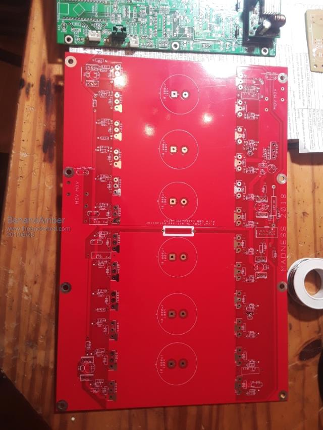 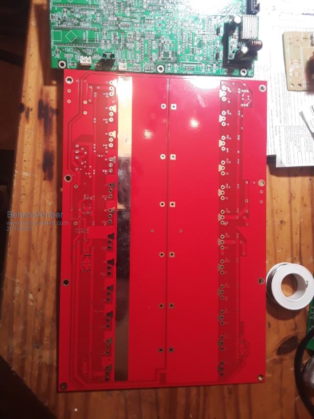 Madness board came in today I was just starting to wonder about it Why was going out I checked the mail and there it was Customs or whatever you call it decided they want to take and look at it also and done a horrible job at taping it back up But it did make it here in perfect condition Pictures do it no justice it's very impressive when you have it in your hand If I ever get enough free time I'm going to try and learn how to use the designing software to make the art for these kind of things If it's anything like all the other electronic stuff off came across it's probably a bit out of my range This board was a real bargain very cheap for what it is be warned i am good parrot but Dumber than a box of rocks |
||||
| BenandAmber Guru Joined: 16/02/2019 Location: United StatesPosts: 961 |
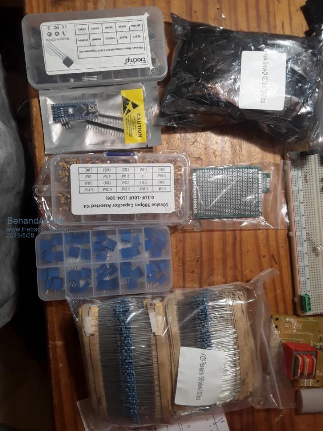 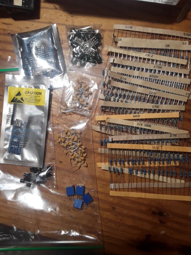 Some parts came in I've been up all night soldering be warned i am good parrot but Dumber than a box of rocks |
||||
| BenandAmber Guru Joined: 16/02/2019 Location: United StatesPosts: 961 |
I found a good deal on the wire (130 pounds) I need to finish my Transformer and my RV solar installation be warned i am good parrot but Dumber than a box of rocks |
||||
| BenandAmber Guru Joined: 16/02/2019 Location: United StatesPosts: 961 |
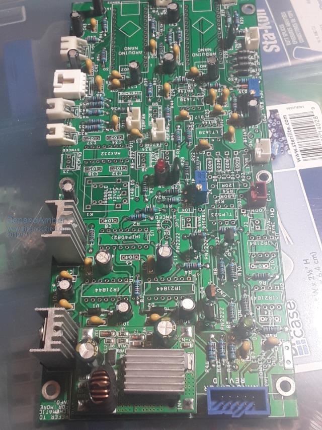  Still waiting on a few parts hopefully they come in soon It's been a lot of fun soldering it up I worked on it when everyone was in bed I put some spacers underneath the LEDs so they would set up a little higher on the board I checked all the components before soldering you never know about some of this Chinese stuff I took my time and went very slow checked and rechecked everything trying not to make any mistakes be warned i am good parrot but Dumber than a box of rocks |
||||
| tinyt Guru Joined: 12/11/2017 Location: United StatesPosts: 431 |
In that condition, it is probably good to test if you have +15V, +12V, and +5V. |
||||
| BenandAmber Guru Joined: 16/02/2019 Location: United StatesPosts: 961 |
That sounds good tinyt do you have a link tell how I hook it up to test it be warned i am good parrot but Dumber than a box of rocks |
||||
| renewableMark Guru Joined: 09/12/2017 Location: AustraliaPosts: 1678 |
Going well Ben, have a look at the bottom of this page Just do those voltage tests, you don't have enough components on there to drive anything yet. Before you start that power board maybe start a new thread for that, there are a few things you need to be careful of. Cheers Caveman Mark Off grid eastern Melb |
||||
| BenandAmber Guru Joined: 16/02/2019 Location: United StatesPosts: 961 |
Okay Mark I sure will thanks for the heads up be warned i am good parrot but Dumber than a box of rocks |
||||
| poida Guru Joined: 02/02/2017 Location: AustraliaPosts: 1392 |
B & A, the board looks pretty good. I just finished my second board today, got it going. How to bring up the nanoverter: First, prove 15V, 12V and 5V, at the DC-Dc converter output, 7812 and 7805 outputs when you feed the DC-DC converter 48V or something like it. While powered up, check there is 15V on pin 7 of the IR21844, and 5V on the 2 nano's supply pins, pin 27 remove power. Don't forget to use pin sockets for both nanos, both IR21844 and both LT1638 Then program both nanos, label them "1" and "2" and install. Maybe it's better or even that it works at all, to program them whilst removed from the board. I had issues when programming one nano today, but I think it was a dodgy item. Bad things happen when you put nano1 into socket 2 or nano2 into socket 1. I did this and blew stuff up. Make up a push button momentary ON switch, to plug into J12. Again, apply power to DC-DC converter, and then when you push the switch, you should see the Green LED D3 light up. press it again and after a couple of seconds or less, it dims. This is when it's handy to have an oscilloscope: press the switch again, D3 lights up and probe for PWM on pin 1 of both the IR21844 sockets. You should be able to see the PWM change as the soft start runs up to maximum duty cycle, to stay there. And then when you press the button again - to stop the inverter - you will see the PWM reduce over 3 seconds, eventually to nothing. Once you see this, then we need to check the correct operation of the IR21844 shutdown pins. These need to be zero volts when not running, even before, during and after you apply power to the dc-dc converter. Then we need to see it go to 5V when you start the inverter by pressing the button. There should be 5V present on pin 2 of both IR21844 sockets whenever the green LED D3 is lit up. After all this, then it's time to install the IR21844 ICS, the two op amps, and provide the 12V AC feedback on J7. We need to turn the VFB adjuster R31 clockwise all the way until you can hear and feel it click, click.. This puts the VFB setting to the lowest output voltage, hopefully much lower than what you will eventually set it to. Remove power. What a little to make sure nothing is on any of the 10 pins of the connector. Connect the 10 pin ribbon to the power board, run the inverter with power supplied to the inverter power board. If all is well, you could then adjust R31 to the required AC output. I would not build the power board with all MOSFETS installed. I would only build it with 1 for each of the 4 legs of the bridge. And I would install a small capacitor, if any, in the DC supply locations. This is the power board I would first try things with, to prove the correct operation of the nanoverter control board as well as the power board. No load testing is needed nor would it be helpful at this stage. And no heat sinks are required when testing it with zero loads. Then once things are going well, add all the MOSFETS, all the DC bulk caps and test it. With the addition of the huge DC bulk caps, any issues will result in a bit of fireworks and the need to replace large numbers of FETS. Oh, and when soldering the FETS, I leave a bit of length on the leads, enough to let me get the side cutters easily onto the leads should I have to replace them. It's best to snip all 3 leads first, then de-solder the short remaining lead bits, rather than try to de-solder the entire MOSFET, 3 leads at once. RenewableMark and I have both found that there is a big difference in 7812 and 7805 regulators, depending on who made them and country of origin. Mark found one reg was getting stupidly hot and not functioning, leading to shutdowns etc. When running, both regulators should be near room temperature. Also, be aware that connecting the laptop to nano2 and opening the Arduino terminal will usually cause nano2 to reboot. This takes a few seconds before it can respond. The LCD shows whats happening. I like using a laptop to do this comms since it is isolated from ground. Mark has found that using a PC, while that PC was powered by the running inverter can give poor results when setting the calibration values. Ground loops probably. When I am setting the calibration values or the temperature settings, I only connect to nano2 when the inverter is not running. Then once the terminal is up and I have the menu (press ? to get it) I start the inverter. wronger than a phone book full of wrong phone numbers |
||||
| BenandAmber Guru Joined: 16/02/2019 Location: United StatesPosts: 961 |
Thanks poida the great It will be a while yet still waiting for parts I took my time when soldering (about 5 hours so far) Looking at every solder joint under a magnifying glass I'm trying to be very cautious This is the first board I've ever put together I want it to look good so I'm facing all the lettering on the components in the same direction Probably sounds silly but it's the first one I have made and I want it to be as perfect as I can make it I am still looking for a laptop if I have to I could use my son's to load the software onto the Nanos I have seen a scope that hooks up to a computer anyone know anything about that Or will one of those small cheap kit ones work for what I need I don't know what I'm doing I don't know if I'd be able to use one that was very complicated Thanks again I appreciate all the help from you guys be warned i am good parrot but Dumber than a box of rocks |
||||
| BenandAmber Guru Joined: 16/02/2019 Location: United StatesPosts: 961 |
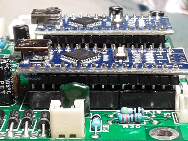 I made some Nano sockets out of regular IC sockets be warned i am good parrot but Dumber than a box of rocks |
||||
| renewableMark Guru Joined: 09/12/2017 Location: AustraliaPosts: 1678 |
Poida the great! That is a great write up for nano test.... excellent. Ben, dunno what sockets you used, doesn't look like they are pushed in all the way. I use this type but doesn't matter as long as you get a connection. Also make sure the USB socket faces out when installed. 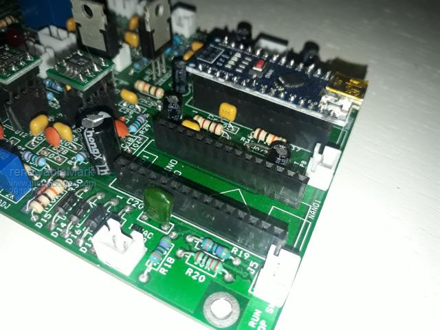 Cheers Caveman Mark Off grid eastern Melb |
||||
| poida Guru Joined: 02/02/2017 Location: AustraliaPosts: 1392 |
B & A you have the nanos installed barse-ackwards. here is mine, with all you need to run an inverter. But - there is no mains sync and no RS-232 support populated. This board works exactly as we need it to. I placed a low power 15V DC-DC converter on it but it can not provide enough amps to run 2 fans. Testing....ok? 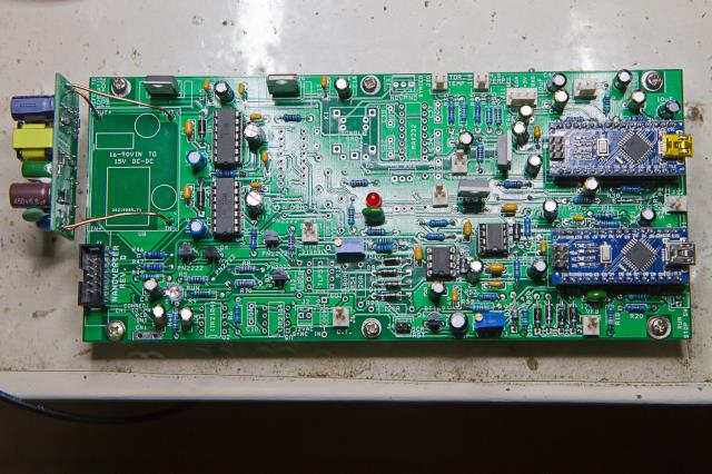 imagur link to full size photo wronger than a phone book full of wrong phone numbers |
||||
| renewableMark Guru Joined: 09/12/2017 Location: AustraliaPosts: 1678 |
Poida you are not using the power supply listed in the build notes. That looks like one of the lower power isolated supply units yeah? Curious why you used that since you had the other type on hand. Cheers Caveman Mark Off grid eastern Melb |
||||
| poida Guru Joined: 02/02/2017 Location: AustraliaPosts: 1392 |
Mark,this is board no. 2. I used the proper supply in board no.1, I only had one of those. This supply is a weakling and can't give enough to run the fans. But it's good enough for testing the inverter. wronger than a phone book full of wrong phone numbers |
||||
| BenandAmber Guru Joined: 16/02/2019 Location: United StatesPosts: 961 |
I'm pretty much done with both of the two Nano boards that I have There's a couple parts that I I still haven't ordered The lt1638 I was trying to find them cheaper somewhere Five bucks a piece 4 through hole $5 for 10 of them a surface mount Almost all the parts of this board is very cheap except for just a few and those few are very cheap if you do them in surface mount Please don't take me the wrong way I'm not complaining I am very grateful to just be able to have a board to build And I am very grateful for all the hard and brilliant time-consuming work that poida the great has put into this This could have been done this way for a reason that I don't have enough knowledge to know about But if these few components were done as surface mount you could build these boards for a lot less than half the cost I do understand that 50 or $60 for a complete control board is already very cheap Please understand I am very grateful and I am not criticizing just saying it could be a lot cheaper I bought resistor kits capacitor kits and on and on everything that could have been bought in a kit that's how I brought it This probably brought the overall cost up quite a bit But all in for 2 boards came up to $152.45 So about $75 a board for me this could have easily been reduced to at least 50 or 60 a board if not less by not buying kits for all the components To compare this a power jack control board is around $129 and 29 shipping 158 for power jack control board 75 for the Nano This is not taken into consideration that's a power jack control board is a piece of crap they tell You themselves have extra parts for it because they know it's going to blow up on you all things considered I'm a very happy camper and I appreciate all the hard work that I get for free Thank you be warned i am good parrot but Dumber than a box of rocks |
||||
| BenandAmber Guru Joined: 16/02/2019 Location: United StatesPosts: 961 |
One of the Nano control board will be going into a 8000 watt 2014 model aluminum case Power Jack It has a bigger than Factory Transformer I will be using the factory main board But the mosfets will be replaced with hy4008 The second Nano will be used later on Madness 8000 watt board I'm going to wait around and get a Transformer that's over a hundred lb for it Up next after the Power Jack will be a attempt to make a warpspeed inverter For anyone that may be wondering the little four mosfet inverter that Poida the great told me how to build Is still going strong be warned i am good parrot but Dumber than a box of rocks |
||||
