
|
|
Forum Index : Microcontroller and PC projects : E100 PLC add-on board...
| Page 1 of 2 |
|||||
| Author | Message | ||||
Grogster Admin Group Joined: 31/12/2012 Location: New ZealandPosts: 9975 |
Howdy.  This board is an add-on to the E100, and turns it into a PLC - Programmable Logic Controller. Often you need to connect either more then 3v3 signals to the E100's CON8 connector, or you need to be able to switch a reasonable current with one of the outputs. As the board sits, you can't do that without extra circuits, so this board is designed to provide that, and to mimic the commercially available PLC's that can be had for considerably more cash. The features of this add-on board are: - Six opto-coupled isolated inputs - SPI port - I2C port - Three COM ports(COM1, COM2 and COM3) - Three PWM pins (PWM 1A,1B,1C) - Twelve high-power open-drain MOSFET outputs 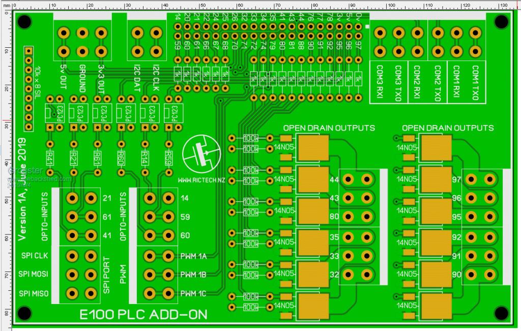 All connections are via spring-loaded terminal blocks, and all parts are through-hole for easy assembly with the exception of the MOSFET's. This board will bolt directly onto the rear of a standard E100 unit. The MOSFET pins are all standard I/O pins that are not currently assigned to any special function, so nothing will conflict. Each MOSFET can easily handle 2A or so continuously. Higher currents can be passed up to 10A or so, provided you de-rate the device and use a suitable duty-cycle to allow the MOSFET's to cool off. You could also fit a couple of rectangular self-adhesive heatsinks to the two columns of MOSFET's to aid in cooling. NONE of the MOSFET output stages have ANY kind of back-EMF snubbing, so if you wanted to drive motors or solenoids, you would have to add back-EMF diodes yourself. This is very easy to do externally on the motor or solenoid itself. For purely resistive loads, no external diodes are required. The numbers beside the terminal blocks are the E100 pin numbers they are connected to. The likes of the COM ports, I2C port, SPI port and PWM pins can all be used as standard unbuffered I/O pins if you are not using the assigned special functions of those pins, naturally. The opto-coupled inputs can have any voltage from about 2v or so up to 50v or so applied to them, and they will isolate and couple this to the E100 pins. The six resistors on the opto-couplers need to be chosen based on the voltage you are planning to connect to these inputs, to provide the correct IR LED current. I have ordered some of these boards, but if anyone is seriously interested in this, I can build a constructors pack and upload it to my website. Smoke makes things work. When the smoke gets out, it stops! |
||||
| RFburns Regular Member Joined: 21/07/2017 Location: AustraliaPosts: 43 |
I would be interested in the constructors pack. Excellent work. Strong like horse smart like tractor! |
||||
| Malibu Senior Member Joined: 07/07/2018 Location: AustraliaPosts: 261 |
That looks great! I'm interested too John |
||||
| Bill7300 Senior Member Joined: 05/08/2014 Location: AustraliaPosts: 159 |
plus one, thanks Grogs. Bill |
||||
| Grogster Admin Group Joined: 31/12/2012 Location: New ZealandPosts: 9975 |
Okey dokey then, I will build a pack. This may take a few days, but I will keep the thread updated. Smoke makes things work. When the smoke gets out, it stops! |
||||
| Volhout Guru Joined: 05/03/2018 Location: NetherlandsPosts: 5931 |
Hi Grogster, I have been using PLC's for a while. There are some things typical about them that you could incorporate in your version of the PLC board. Typically PLC outputs drive high (they pull the load connected to ground to +24V). Typically PLC inputs sink current (like your optocouplers), but need at least 2mA before they see a "high" level. That is to support 2 wire sensors (like 2 wire hall sensors). Inputs and outputs are protected. Serial ports: PLC's typically support RS485 (modbus) protocol. If you design 3 serial ports, you may want to change 1 into RS485. Maybe you are capable of squeezing in these features above through "optionally loadable" components. Would make your board more versatile. Regards, Volhout PicomiteVGA PETSCII ROBOTS |
||||
Bill.b Senior Member Joined: 25/06/2011 Location: AustraliaPosts: 245 |
I have used this board from banggood were I required a PLC type interface at AU$27 it is reasonably priced. https://www.banggood.com/8CH-Channel-PLC-DC-Output-Transistor-Amplifier-Isolation-Plate-Board-p-1497172.html?rmmds=newAr rivals&cur_warehouse=CN 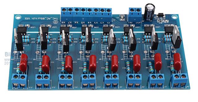 Bill In the interests of the environment, this post has been constructed entirely from recycled electrons. |
||||
| Volhout Guru Joined: 05/03/2018 Location: NetherlandsPosts: 5931 |
Hi Grogster, Another thing you may want to look at is the current flow through the power MOSFETS. There are thick copper traces to the connector (from the drain). But how the the ground current flow ?? I hope there are some via's near te source pins..?? 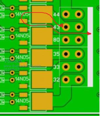 Success, Volhout PicomiteVGA PETSCII ROBOTS |
||||
| Grogster Admin Group Joined: 31/12/2012 Location: New ZealandPosts: 9975 |
Hi there. Outputs 90-97 connect directly to the surrounding ground-plane, but yes, outputs 32-44 don't have ideal ground current paths. I will improve on this. As you have had experience with PLC's, can I ask you how they are programmed? Do they use a propriety language etc? One would assume that as they are used quite a bit in the electrical trade these days(including as modern elevator control to replace all the relays), one would assume that they can't be hard to program or otherwise setup. I know of their existence, but have never used one, so the programming/setup of a PLC has always been a missing part of my general-knowledge when it comes to PLC's, so any information you can give me here would be useful for the long-term-storage in my head.  I would consider making one bank of the MOSFET's drive high, and leave the other as pull low. I will have to see if their is an complimentary MOSFET for the 14N05, which always just works right out of the box - which is why I used them.  High-side switching seems to often need a 'Helper' transistor on the MOSFET and a couple of resistors, which is more parts to squeeze onto the board, but that might be worthwhile so that some channels can be high-side drivers, and the others can be low-side, then both are catered for. Smoke makes things work. When the smoke gets out, it stops! |
||||
| Malibu Senior Member Joined: 07/07/2018 Location: AustraliaPosts: 261 |
Hi Grogs, just my 2-bobs worth here... As Volhout says, PLC outputs are normally switched on the high side. There's a few reasons, but partly because it's easier in the real world wiring to tie 0V to ground and when it comes to fault finding, there's always a handy reference nearby. As I say, there's a few reasons but switching the high side is just the 'accepted way' to do it. (As a comparison, in an AC system it's against regulations to switch a neutral, so electricians compare 0V to Neutral and treat them as the same potential) The input currents are probably a result of problems with 2-wire devices (usually proximity switches) not changing state when turning off - sometimes, when the current is so low, the proximity current will not reach its off-hysteresis curve and remains 'on' without a higher current to snap to the off state. It was a big problem with early design PLC's. To answer a couple of your questions, PLC's are usually programmed with ladder logic and while it's not proprietry, there's a lot of variations out there. Siemens S7 is a nightmare and is kind of a procedure based ladder logic. Omron (and most others) just use basic ladder logic and is pretty easy to pick up the basics. There's heaps of examples of how it's written on the web. I use mainly Omron (with CX-One programming system), but I've also dabbled with AB, Siemens, Toshiba, Mitsubishi plus various other odd-ball brands. Some have even been custom designed PLC's that were programmed in assembly. These days, it's pretty hard to find an industrial machine out there that DOESn't have a PLC in it, so I think you're on the right track with this idea. Just as a suggestion, think like an electrician in your design! Most electricians are only interested simple I/O, so the more I/O's you cram in the better (more appealing) it would be. The only other idea I could throw out is to incorporated one (or two) of the COUNT inputs into it. There's a lot of times sparky's need a high speed counter input (encoders, etc...) Maybe another suggested option is relay outputs instead of FET's - there's plenty of wiring that use 24VAC (even 240VAC) control wiring. My background is as an industrial electrician in breakdown service for 35 years. Wow... this is bigger than I planned, sorry! Hope all this makes sense!  John |
||||
| Bill.b Senior Member Joined: 25/06/2011 Location: AustraliaPosts: 245 |
Hi Grogs As John has indicated think like a eleco. this is a sample of ladder logic that is the basis of most PLCs. 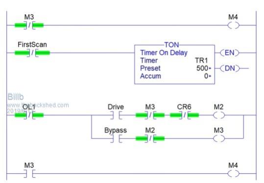 Bill In the interests of the environment, this post has been constructed entirely from recycled electrons. |
||||
| Malibu Senior Member Joined: 07/07/2018 Location: AustraliaPosts: 261 |
That's a perfect example of generic PLC ladder! (Just out of interest, I looked at my old Omron CS1 Programmers Reference book... There's 1400 pages of functions and programming descriptions in it. That's just for ONE series of PLC in the Omron range!) John |
||||
| Grogster Admin Group Joined: 31/12/2012 Location: New ZealandPosts: 9975 |
I don't understand 'Ladder-logic' at all. I will have to do a little research. Bill's image means nothing to me. EDIT: Found this on Wikipedia... As to the outputs, it's funny you should mention the COUNT thing, as that is something I am adding to the next version of the board, and have already started doing it. Three counting inputs on the COUNT pins on CON8. Do you think that relay outputs are a better idea then MOSFET's when we're talking PLC-ish concept? Perhaps this is much more in the realm of sparkies, and everyone knows how to wire up a relay to do what they want. They also have the advantage that you can wire up the contacts for whatever voltage, however you want, and are not 'Forced' to do it via MOSFET's. I am seriously thinking about this now... The only thing is that relays are much bigger physically then MOSFET's to handle the same current. Food for thought though. Smoke makes things work. When the smoke gets out, it stops! |
||||
| Malibu Senior Member Joined: 07/07/2018 Location: AustraliaPosts: 261 |
Hi Grogs, LOL... it's actually pretty simple, just a different schematic style than what you're probably used to. Try this one as something easier... 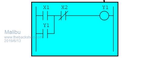 A straight forward motor stop/start. Any element on the right are the controlled devices (even internal ones like timers, counters etc...) and in this case it would be a contactor output for a motor. Any element to the left of this is controlling device (switches, proxes, internal contacts etc) In this case, 'X' are inputs & 'Y' are outputs, so on the top line, when X1 (a N/O start button) is closed the circuit is made through X2 (A N/C stop button) and turns Y1 on and the motor starts. On the 2nd line, Y1 is an internal 'software' contact (that works with the output) closes in parallel to X1 and when X1 is release, the Y1 output remains on (Y1 here is a hold in contact) The motor runs until X2 is pushed, opening the circuit, turning off the output, dropping out the hold in contact ready for the next X1 push. In the old programming style, this would be written as : LOAD X1 OR Y1 AND NOT X2 OUT Y1 (If my memory doesn't fail me) Excellent! It's horses for courses and there's all different types of PLC's out there. I prefer relay because they are more versatile, but in a purely DC control board, FET's would be OK. You'd find most sparkies would use this output style to control slave relays to control higher current devices. I put my hand up for one of these, and the first plan I had was to make a relay slave board to get around some of the problems already discussed. What's your long term plan for this? Are you looking to market a PLC type controller for electricians, or just as an added extra to the E100 for sheders? John |
||||
| Grogster Admin Group Joined: 31/12/2012 Location: New ZealandPosts: 9975 |
Thanks for that. Yes, I have read through the Wikipedia page on it, and I understand it now. I had never heard of that concept before, so it was new to me. I'm really only targeting an extra for E100 shedders, but if it had the right selection of bits on it, it could make the touch-screen E100 more useful in those areas too. You can get those small DIL relays, which are good for an amp or so and they are normally DPDT, and I could fit plenty of those on a board. Sparkies would still need to slave another relay off that again to switch a decent load, but this WOULD allow high or low switching methods - whichever you want. Hmmmmmm...... Smoke makes things work. When the smoke gets out, it stops! |
||||
| Volhout Guru Joined: 05/03/2018 Location: NetherlandsPosts: 5931 |
Hi Grogster, If you want to play with ladder logic a bit, you can look at this: LDmico This program let's you program in ladder logic, and simulate it. It also generates binaries that can be programmed directly in some older 8 bit PIC and AVR devices. The PIC code is far more efficient than the AVR code. It is by no means a complete ladder compiler, but it gives an idea. Ladder code consists of "rungs" that have the input at the left side and output at the right side. One thing that is crucial to PLC's, is that they have a cycle time (TACT time). That is the repetition rate in which all code is executed. At the beginning of the cycle, all inputs and all outputs are sampled/set. Then logic functions are executed. And then it waits until the next cycle starts. This is very different from MMbasic, where everywhere in your program, you can change IO pins and read A/D. But it is simple to change MMbasic to perform as a PLC. You have to write a timed interrupt routine. In this routine, you update all IO. In the main program you can change variables, but not IO directly. This cycle time is very important in control loops. Digital control loops are designed around a sampling speed (PLC cycle time) and the real world electro mechanical timing variables (i.e. weight/mass and applied force). By the way, within the PLC world there are 3 or 4 standardized ways of writing PLC code. There is also an ASCII (text based) way of writing the same rungs as in ladder. Regards, Volhout edit: someone picked the sleeping LDmicro project up in 2015. It has become a more mature product that also supports arduino now and ESP. see: https://github.com/LDmicro/LDmicro PicomiteVGA PETSCII ROBOTS |
||||
| CaptainBoing Guru Joined: 07/09/2016 Location: United KingdomPosts: 2171 |
Headsup on those beasties, some variants include a snubber diode internally (on the coil) - they don't work if you get them the wrong way round coz the diode shorts the coil when not reverse biased (as you know) - make sure your board layout can cater for either type - I think the -ve is the nearest pin viewed from the top with the coil on the right. might also want to put provision for a 1n4148 as well for the other type jus' sayin' |
||||
| Tinine Guru Joined: 30/03/2016 Location: United KingdomPosts: 1646 |
Served my apprenticeship building relay control panels and I wasn't satisfied with boring point-to-point wiring so I made it my business to understand as much as possible about how the logic worked. Soon became very proficient and I picked up on errors all the time. Then the Gould Modicon arrived with its ladder logic...of course, being a keen student, I picked it up in no time but it seemed moronic to be writing logic that way...no flow to it, it only existed for the old-boy electricians who were untrainable in procedural languages. For process control, I LOVE BASIC's ON-GOSUB structure, this is a simple example of what I have been doing since the mid 80's, AKA: a state machine: Pseudo code: Seq_step = 1 Do [Put code here that needs to be constantly attended to] ON Seq_step GOSUB L1,L2,L3,L4,L5,L6,L7....etc. Loop L1: [Do something like set an output and wait for a corresponding input (sensor)] If Sensor = True Then Seq_step = Seq_step + 1 RETURN L2: [Make something else happen and increment Seq_step when satisfied] RETURN L3: RETURN . . . . . . . If MM Basic is the same as every other BASIC that I have come across, it creates a Jump Table so that GOSUB L1000 takes no longer to jump to than GOSUB L1. Select Case would require testing every possibility and would, therefore take longer as Seq_step increased. A passive time delay? L60: TmDel = TIMER + [required ms delay] : Seq_step = Seq_step + 1 : RETURN L61: If TIMER > TmDel THEN Seq_step = Seq_step + 1 : RETURN |
||||
Quazee137 Guru Joined: 07/08/2016 Location: United StatesPosts: 603 |
My Pi w Zero's is setup as PLCs and I use these for output 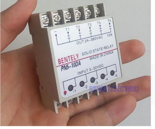 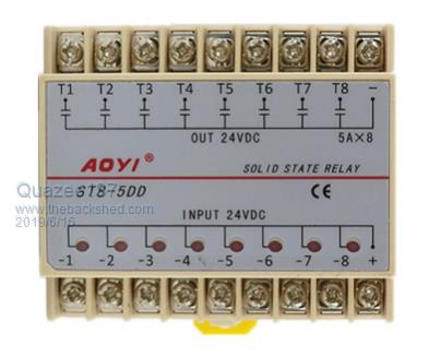 Din Rail Mounting. My inputs are optocoupler based. Have a look here OpenPLC Been waiting for free time to try and do a PLC using the 128K FRAM on a 28 pinner and custom character sets. Then using one of the bigger Mites maybe easier using the GUI's . Enjoy Quazee |
||||
| Tinine Guru Joined: 30/03/2016 Location: United KingdomPosts: 1646 |
Agree re: Outputs driving high. I use SSRs pretty much exclusively (dirt cheap on Ali-whatever) unless I need the isolation of mechanical contacts. Mechanical relays don't last very long, in my world, when switching DC inductive loads (hydraulic solenoid valves). I would/am considering MOSFETS on the PWM outputs, though, because I can electrically regulate the valve flow and eliminate manual adjustments during machine setup. P-Channel would be more convenient though or I have some more rewiring on my hands. RS485 on E100: I have full duplex (4-wire) 485/422 on this machine right next to me. The E100 is the master and with it being a full-duplex arrangement, the TX is dedicated to just that. Therefore the DE is tied high at the E100 end. The RX is a shared response line and so only the slave devices switch their DE on when responding to the E100 (speak when spoken to). This means that my E100 behaves as if it were communicating via RS232. |
||||
| Page 1 of 2 |
|||||
| The Back Shed's forum code is written, and hosted, in Australia. | © JAQ Software 2026 |
