
|
|
Forum Index : Electronics : Tinkers warpinverter
| Author | Message | ||||
| Warpspeed Guru Joined: 09/08/2007 Location: AustraliaPosts: 4406 |
Reducing the capacitance down to the core would definitely be helped by putting some distance between the core and the first layer of the secondary. That cannot be done around through the centre of the hole obviously, but Klaus's idea of rounded cheek plates are an excellent step in the right direction. An extra belt of something fairly thin around the outside of the core might help even further. This would make no noticeable difference to the total length of wire or the final ohmic resistance of the secondary. I am pretty certain this is not going to be a problem for us at 48 volts anyway, but it all becomes worse with a primary wound for a much lower dc supply voltage. The secondary to core capacitance may remain the same, but with a larger required voltage step up ratio, the primary becomes more difficult drive, and the primary current proportionally higher, including the current spikes at the transitions. This is another hidden advantage of a warpverter. With PWM, you need to have a higher transformer voltage step up ratio, say typically 9:1 for a 48v inverter, where perhaps a 38v minimum design battery voltage is required to generate a 340 volt peak sine wave. An equivalent warpverter would only need to generate a 225v peak square wave from the same 38v design minimum supply, so the transformer ratio would be more like 5.9:1 instead of 9:1. So you will all discover that your warpverter primaries will require about 50% more turns, and of proportionally thinner gauge wire than an equivalent PWM inverter. The primary current of the largest toroid will be lower too for the same final power output. That missing output power comes from the other three inverters doing their share of the work. The mosfets all get a much easier time too, although there will be more of them all working together. All the extra hardware in a warpverter spreads the load around away from just the largest inverter. So I would not dwell too much on this current spike problem, Its not likely to be an issue for us anyway at 48v and above. And there is the choke cure available for it anyway if it does arise. Cheers, �Tony. |
||||
mackoffgrid Guru Joined: 13/03/2017 Location: AustraliaPosts: 460 |
I contemplated using a buss bar in contact with the circuit but was worried about the longevity of of the connection, vis-a-vis oxidation. I'm not familiar with products like Alminox - so Thankyou. I'm using aluminium, as part of the heat sink, as a buss bar and I am using a "proper" nickel plated copper buss bar for the negative rail, which was leftover from my solar install seven years ago. Now that nickel plated buss bar has tarnished - blackened quite a bit, more than I expected, probably where I stored it and the bad Brisbane summers did the job. What I am leading up to is; Is the oxidation on aluminium less of a problem than the oxidation on copper or even brass (as is standoffs etc) - So is aluminium, where size is not a constraint, a better material for a buss bar? Cheers Andrew |
||||
| Warpspeed Guru Joined: 09/08/2007 Location: AustraliaPosts: 4406 |
Most things will oxidize over time if exposed to air or moisture, the trick is keeping the air and moisture out of the joint. A properly made crimp works, and so does very solidly bolting the parts together. I remember reading something a long time ago that mentioned a special grease that had fine metal particles (silver ?) that are supposed to bite through any residual thin oxide layer, and the sticky grease excludes air and moisture after the joint is clamped up or crimped very tightly together. The ultimate solution is probably tin plated copper. Food cans are tin plated steel, and they stay in pristine condition for years, unless the tin layer gets damaged. Tin, or lead tin (solder) plating of circuit boards works pretty well too. The chemicals for do it yourself electroless tin plating are pretty readily available on e-bay, and it would be quite practical to tin plate copper busbars yourself. https://www.youtube.com/watch?v=2Lr0IV33GJw I have done this successfully myself, but the copper must be perfectly clean and shiny, with zero greasy finger prints ! And the chemical brew once mixed up will not keep very well in storage. You need to mix it and use it, then toss it out. Another alternative to that would be tinning the copper with ordinary solder where the jointed surfaces are. Then bolting the parts together. That is probably the easiest of the lot. There is a company "George White" that sells copper rectangular bar in all the same sizes you can buy rectangular aluminium bar. Branches in Sydney and Melbourne. http://www.georgewhite.com.au/products/product_listing.asp?categorycode=CB-F I just used aluminium busbars without the grease, but if it looks like giving me trouble I can upgrade later to tin plated copper easily enough. So I think build up your inverter first with aluminium busbars, as aluminium is cheap more readily available, and very easy to work with. And maybe upgrade to tin plated copper a few years hence if the aluminium starts showing real signs of distress. Cheers, �Tony. |
||||
| BenandAmber Guru Joined: 16/02/2019 Location: United StatesPosts: 961 |
I used the anti oxidation electricians Greece that's made for aluminum wire connections it's code in the United States I seen a YouTube video of a guy spraying out of a spray can this stuff that protects aluminum and keeps it from oxidizing be warned i am good parrot but Dumber than a box of rocks |
||||
| Tinker Guru Joined: 07/11/2007 Location: AustraliaPosts: 1904 |
I am presently winding the secondaries of the 4 warpinverter transformers and came across something perhaps worthwhile passing on to the unwary. There are 3 parallel windings, each of 160 turns. I only count (three times  ) the turns of first winding. ) the turns of first winding.For the following winding I power up the first winding to its rated voltage and measure at the other winding, adjust turns until they are equal. Nothing new so far , standard practise. But, AC digital voltmeters are not equal I found out  . .I have several but one of them measures 'true RMS', the others just the usual rectified AC voltage, There IS a difference of one Volt! The winding has 1.42V/turn, so that meter display difference could mean one turn out when you think its correct. So, poke each multimeter's probes into a power socket first and see if the reading is the same to test for that possibility. My completed windings were within 0.1V from one another. If yours are not start investigating why. Klaus |
||||
| poida Guru Joined: 02/02/2017 Location: AustraliaPosts: 1390 |
True RMS meters usually contain an IC that does the RMS conversion. Plain old meters without true RMS make educated guesses at the AC voltage, mostly assuming the waveform of the AC signal is a close approximation to a sine wave. If the waveform is exactly a sinewave, it is easy to display the ac voltage and be accurate. If it's a close approximation of a sinewave, peak to peak voltage can be used, then divided by 1.414 and obtain the RMS voltage. But if the waveform contains a lot of other harmonics, that is, it might be a squarewave or some sort of fanken-wave (recall the ugly AC output of that junk generator I had), then we will see differences. the wikipedia article on true RMS converter is useful I am lucky right now, I have 3 Fluke DMMS that offer true RMS AC readings. Don't get me started on measuring voltages and current. I should draw a line under this now. It is very educational to spend an hour feeding various waveforms from the function generator into a true RMS meter and a meter that just offers "AC". wronger than a phone book full of wrong phone numbers |
||||
| mackoffgrid Guru Joined: 13/03/2017 Location: AustraliaPosts: 460 |
Good to know. Its one winding per core, right? |
||||
| Tinker Guru Joined: 07/11/2007 Location: AustraliaPosts: 1904 |
Not quite sure what you mean there. I have 3 parallel windings on *each* of the 4 cores for the secondaries, giving me 6.8mm sq wire area total. My house is powered by inverter off grid so its this AC I was using to power my Variac (which is isolated by a 1:1 transformer). Klaus |
||||
| mackoffgrid Guru Joined: 13/03/2017 Location: AustraliaPosts: 460 |
Okay I'm with you. I haven't appreciated the difference in meters, as you say pre-check you test gear. I could suggest another way to check your windings, in a similar way I check the polarity of the transformer. 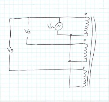 Connect up the windings as I've shown, I prefer to use a isolated AC source at safe voltage, obviously it must be under the rated volts / turn . V2 and V3 should measure zero volts if they are balanced. A warning, that if polarity is wrong you'll get 2 x Vin. Cheers Andrew |
||||
| Warpspeed Guru Joined: 09/08/2007 Location: AustraliaPosts: 4406 |
It can difficult with a higher voltage winding to be absolutely sure with a direct voltage measurement. The grid voltage can suddenly change during the test which can sometimes be confusing as well. If you have three windings A, B, and C, start by energising A from a variac or whatever. Connect B and C together at one end only, and measure the difference across the two wires at the other end. Should be almost nothing. If there is about a volt or or so, probably one turn difference. Then energise B, and compare A and C. Then energise C, and compare A and B. A small 3v torch globe works pretty well for this test too. Cheers, �Tony. |
||||
| Tinker Guru Joined: 07/11/2007 Location: AustraliaPosts: 1904 |
Interesting, the many ways this could be done. I just use two AC multimeters (after checking they measure the voltage at the same powerpoint identical ) and an AC milliampmeter.Power up one winding via variac, connect the other winding to the second voltmeter and see the voltages on both meters rise in step. On the big transformer, wind the volts up to 225 and measure the idle current (35.5mA)  . .Repeat for the third winding. The remarkable thing was I could switch the 225V on and off, wired up as above, without blowing the milliampmeter. One Tesla takes the sting out of toroids  . .Another test I do is using my shiny new Megger tester and check between the individual winding ends (other ends open), 500V test voltage. All passed .One can never be sure when using second hand enameled wire. Just out of interest I connected a single shorted turn to the powered core. The milliampmeter shot up to 400mA and the wire got hot rather quickly. So, shortened turns would be quite obvious... Klaus |
||||
renewableMark Guru Joined: 09/12/2017 Location: AustraliaPosts: 1678 |
Doing the volt check is clearly needed, but WTF wouldn't you count the bloody turns on progressive secondary layers? I count 25 then put a white mark, check it probably five times before the final is decided. Then before cutting the wire, 1 metre gets left on the loose end. Do the volt check, if all OK then most likely fine. Put one extra turn on, just to confirm a rise in volts. If that tests as predicted then go back to the correct turns. All confirmed then cut as req'd and do next secondary. Cheers Caveman Mark Off grid eastern Melb |
||||
| Tinker Guru Joined: 07/11/2007 Location: AustraliaPosts: 1904 |
I prefer to concentrate on my winding technique and not get distracted by keeping count .With 160 turns per layer on the big one, I first calculate how many turns could fit theoretically once round the hole rim. In practice this is likely to 5-10% less of that number, depending how straight the wire through the hole is. Once complete around, I count them, marking each 10th turn with texta pen. It turned out to be within I turn of what I wanted, so I added that turn. The next layer is just wound in similar fashion around the hole but the counting replaced by voltage measurement once completely around. No need to count again as this voltage measurement is required anyway and I knew by then how many turns could fit. This works for me , BTW, I wind these things differently than you do. You can read about that in my next warpinverter building installment. Klaus |
||||
| Warpspeed Guru Joined: 09/08/2007 Location: AustraliaPosts: 4406 |
We all develop our own little tricks, and a method, after doing this a few times. Whatever you think is going to fit onto that core theoretically, never does. There needs to be a very generous allowance for both turns per layer, and build height due to layers of insulation, and the wire never laying completely flat. Klaus is right about one Tesla being very benign. But it does use up a lot of extra steel and copper to achieve such a low flux density. That is one huge advantage we have over the commercial transformer designer guys, we being able to use free or cheap recycled materials. Our transformers will end up being enormous compared to theirs, but will have a much lower idling current and a minimal inrush at power up. So they end up with something cheap and small, but we end up having something much nicer that works a whole lot better. There is a vast difference between designing something just for ourselves as a hobby project, and designing something for the competitive mass produced commercial market. Cheers, �Tony. |
||||
| Tinker Guru Joined: 07/11/2007 Location: AustraliaPosts: 1904 |
Having finished winding the secondaries on all 4 transformers now, it was quite a task - pulling that wire 1035 times through a toroid hole . Now I can look forward to repeat that exercise 437 times with the primary winding's.Anyway, the big toroid was made up from 2 x 3KW Aerosharp cores. I epoxied those together. 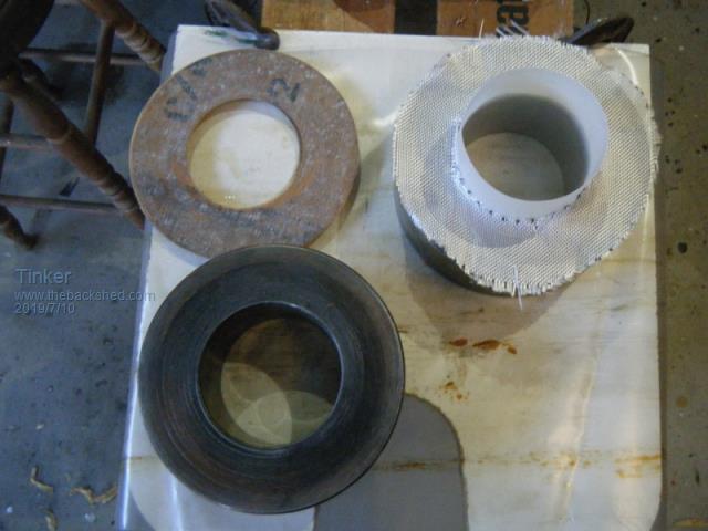 The glass mat evens out the core surfaces for a very solid connection. You do not want that to break while wrestling with that 22kg lump of steel to wind the wire on. Here are the two cores mated up. 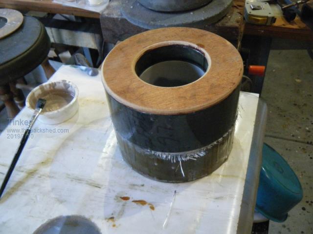 Note that I use 6mm plywood disks with rounded edges on the core faces. The 4 cores are ready for the winding part. In the background is my stack of re cycled wire for the job. 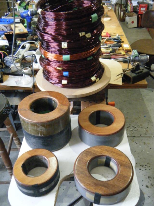 Here I show how I wind them, the wire is first fed into my muscle powered winding machine. The white on the core outside is a layer of 1mm plastic which I fitted to all cores to minimise that troublesome capacity problem Macoffgrid encountered. 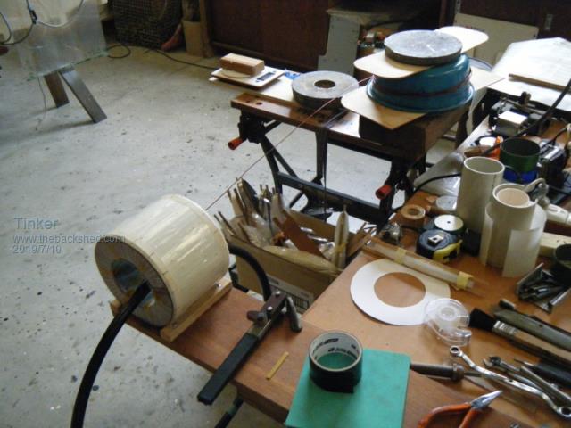 The eagle eyed may spot my wire pulling gadget next to the core. The enamelled wire *must* be very taut in the toroid hole or one looses valuable hole space. A close up how the wire gets inside the 'winding machine' by means of a small plastic strip. 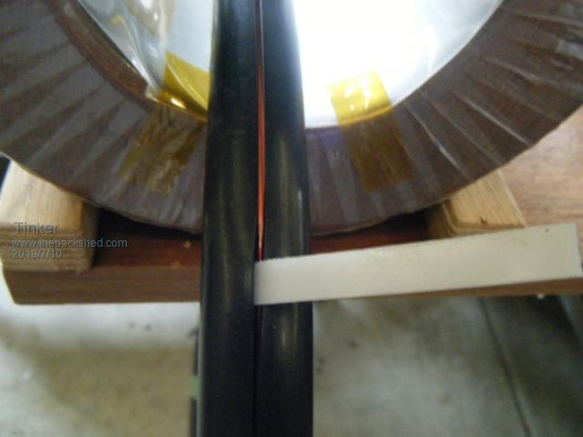 My secondaries are wound 3 in parallel on each core, here is a pic of the first completed. 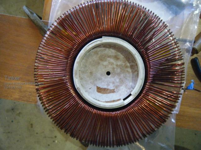 Note the split PVC tubing jammed inside the hole with a wooden disk. This pushes the wire right against the core while the epoxy sets. I repeat this for every parallel winding. Another pic with the second of the parallels. 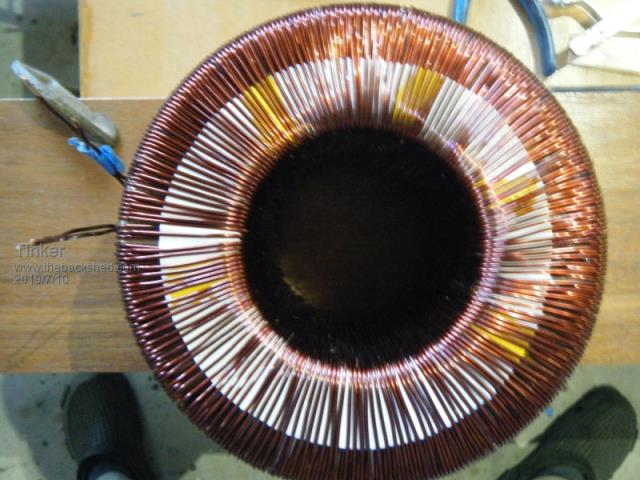 I count the turns only on the first run, the next pic shows how. The second run was alternated between the first, thus not requiring counting. As there are 160 turns per parallel winding this helps a lot. Below is the partly completed first winding on the transformer #2. It shows the kraft paper (200g/sqm) disks I use with marks for every 10 turns. By sticking to the marks I can get the turns evenly spaced around the core. 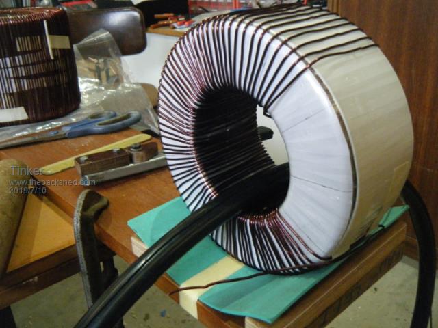 Now all 4 transformer have their secondaries on. 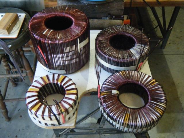 I had elected to fit a full static screen between the secondary and primary winding of each transformer. The biggest core looked like the most difficult to fit that so I started with that. 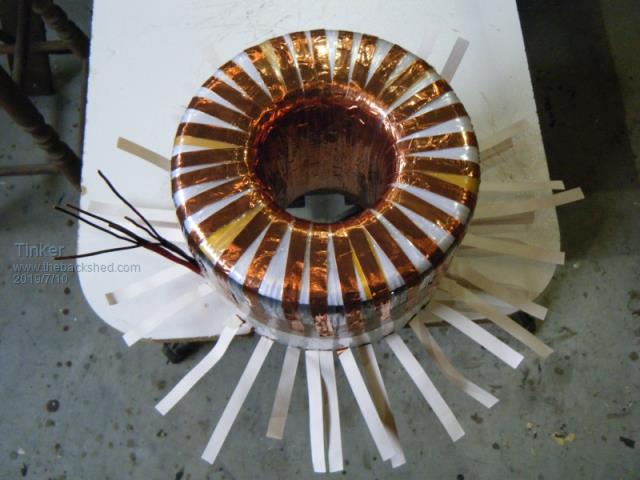 Using my 'grass skirt ' method, 10mm wide strips were first placed inside the hole so the copper foil made 100% cover in there.This was followed up with 20mm wide foil strips to cover the still bare sections on one face of the toroid. 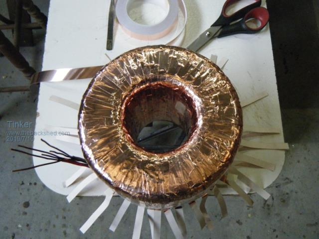 Here is a side view to show the heat resistant tape the foil ends terminate over. A 20mm foil strip ran around the circumference above that. 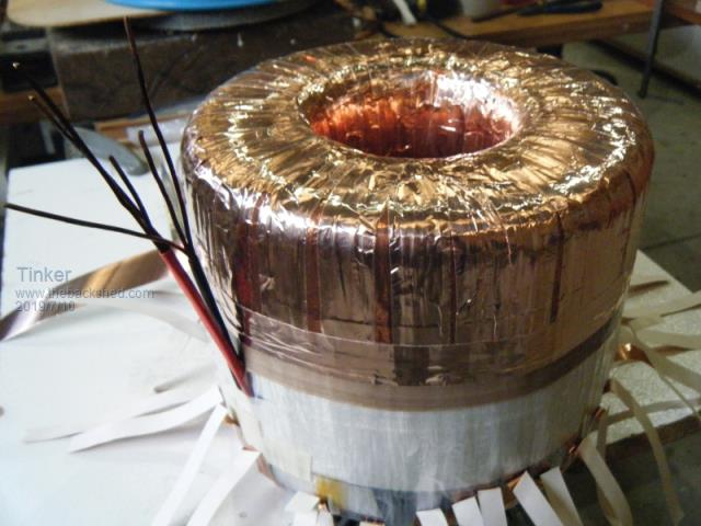 And finally the other (skirt ) side was completed similarly.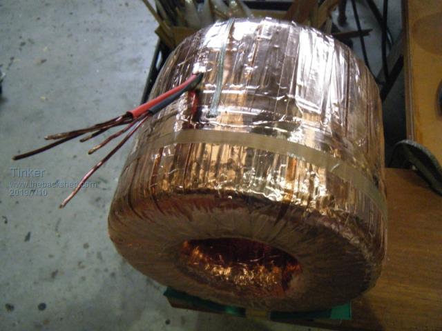 A earth braid was then soldered on and the core tested first for shorted foil by powering it up and observing the idle current. It was the same so no short .Then I did a 500V Megger test between the screen and the outer layer secondary winding - it passed. Next installment, the primary winding's. Klaus |
||||
| mackoffgrid Guru Joined: 13/03/2017 Location: AustraliaPosts: 460 |
Great post Klaus. I thought everyone went to the solder reel method of winding transformers - Nice to see the big hoop. Is that poly-pipe? Do you get a whole winding loaded into that hoop? Cheers Andrew |
||||
| Warpspeed Guru Joined: 09/08/2007 Location: AustraliaPosts: 4406 |
A really beautiful job there Klaus, each of your pictures is worth a thousand words. There are a lot of very good ideas and excellent workmanship demonstrated here. The hoop idea is pretty much how the automatic coil winding machines work, and it must certainly go a very long way to avoiding kinks and stresses in the wire. Cheers, �Tony. |
||||
| Tinker Guru Joined: 07/11/2007 Location: AustraliaPosts: 1904 |
Andrew, the solder reel method is doing it Flinders island style , I prefer to copy the method commercial toroid core winding machines use.I also found it much easier to wind the cores lying sideways, the complete turn can then be inspected without having to lift the core. Yes, its 19mm black poly pipe. My 600mm dia hoop can hold 1kg wire easily. It did the whole winding on transformer 2-4. The recycled wire was too short for the double stack No. 1 transformer so I had to fit one splice at each of these secondaries. The hoop could do the whole winding if my wire was long enough... Klaus |
||||
| Tinker Guru Joined: 07/11/2007 Location: AustraliaPosts: 1904 |
Thanks for the kind words Tony. There were kinks created by my wire puller but these are on the outside of the core and easily flattened with my plastic faced hammer. Unfortunately 1.7mm wire is too stiff to pull tight around my rounded core corners by hand. I do like the hoop winding method, it does take a bit of figuring out initially with regard of which way to load and use the wire from it . What is pictured suits a left handed person .Best of all, its a sitting down job . Klaus |
||||
| mackoffgrid Guru Joined: 13/03/2017 Location: AustraliaPosts: 460 |
I keep looking at your photos - building a picture in my mind what you're doing. Great reference photos. I very much doubt I would have re-purposed AeroSharp Chokes without your posts. Could I get a close-up of the wire pulling tool - I can't figure it out. It'll be very interesting to see how your capacitance goes. Cheers Andrew |
||||
