
|
|
Forum Index : Solar : Solar Component Hackery.
| Author | Message | ||||
radar Newbie Joined: 09/06/2019 Location: AustraliaPosts: 16 |
Hi Davo99 , QUOTE:"I'm surprised the Chinese haven't produced a board for this purpose, maybe they will in the future? I wonder what I would cost to commission one and have them made to sell? " Well dave there is equipment out there fit for purpose . It is a Grid tie Inverter with the anti islanding software deactivated . Or never part of the inverter to begin with referred as a something island inverter. If somebody here can come up with a circuit to stop the GTI back feeding But allowing it to sync to a cheap $30 Off grid inverter you now have a something island inverter . You would need to power the ogi with Mnn a car battery or similar . And keep it topped up with a pv panel and charge controller . Or the power to keep the battery topped up can be borrowed from the gti But then it's getting into the area of it not being kept simple as you had hoped for . Radar. |
||||
| Warpspeed Guru Joined: 09/08/2007 Location: AustraliaPosts: 4406 |
Mike has nailed it. The main attraction of the capacitor charge pump system is its absolute simplicity, efficiency, and low cost. There is also very little there that can go wrong, so it should be very reliable. My old solar panel tester works in a very similar manner. 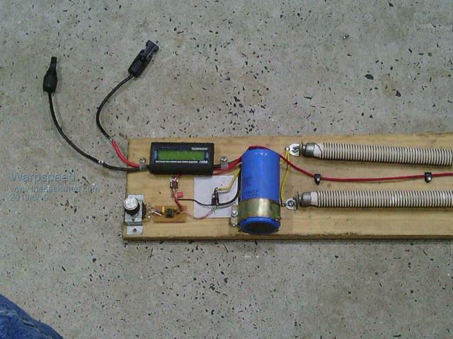 There is a relatively large electrolytic connected to the 24v solar panel via a Turnigy power meter. A pair of nine ohm radiator bars connected in parallel are switched by a mosfet as a discharge load. The mosfet gate is driven by a 555 that has an adjustable duty cycle from almost zero to almost a hundred percent. By tweaking the potentiometer I can adjust the constant steady loading on the solar panel from almost nothing up to a maximum load of about 4.5 ohms, and read off voltage, current, and power at any loading point. Its dead easy to find the max power point, and measure how the power falls away at higher or lower panel voltage. Its all very simple and efficient and works amazingly well. A higher voltage version connected to a hot water heater should be just as efficient. Cheers, �Tony. |
||||
LadyN Guru Joined: 26/01/2019 Location: United StatesPosts: 408 |
With my limited knowledge, I would say inductors or transformers are more reliable than capacitors. capacitors are large, they can dent, harder to keep cool, the electrolyte dries out etc etc inductors or transformers are all metal - you can't get more reliable than that and as simple as it can get (atleast the ones we use) However, it might very well be capacitors are a much easier approximation of a battery with good discharge ratings for our purposes than an inductor - in which case all we have to use are capacitors. simplicity, yes - not yet sure about low cost but thats because I am yet to understand capacitors and inductors wrt to their storage ability properly. capacitors can really store a lot of charge/energy over a period of time minus the internal (and environmental) losses - possibly over the ESR. It's easy to understand and experiment with. inductors are a bit more difficult for me to grasp - they develop a voltage in response to a changing flux - but is there a way to store energy over a period of time comparable to that of a capacitor? |
||||
| Warpspeed Guru Joined: 09/08/2007 Location: AustraliaPosts: 4406 |
Capacitors can be extremely reliable, provided they a properly specified and of a type suitable for the job. Cheers, �Tony. |
||||
| Solar Mike Guru Joined: 08/02/2015 Location: New ZealandPosts: 1123 |
No, energy is used to build up the magnetic field in an inductor and there is a formula for that, P = (LI^2)/2, where L = inductance and I = current, basic high school physics lesson 101. But that potential energy dissipates soon as the current is stopped and the magnetic field collapses, unlike a capacitor where the energy is stored and held. So one would use a circuit containing an inductor or transformer if both the voltages and power had to be converted from one level to another. In Davo99's case his PV voltage is practically the correct match for the element so voltages do not require conversion, only current; the panels output 8.3a, the element requires 15 amps. The capacitor acts as a current booster or pump, the performance and reliability being determined by the quality of the capacitor, a low esr cap is essential and they are not cheap. Even so the complete parts list would prob cost approx $100 and last >15 years, seems good value to me. High DC voltages are extremely dangerous, more so than AC, so this sort of circuit is lethal and shouldn't be attempted without suitable skills, but if its contained inside a fully insulated case with suitable plugs in and out, then would be safe to handle at least. Cheers Mike |
||||
| BenandAmber Guru Joined: 16/02/2019 Location: United StatesPosts: 961 |
A Transformer or inductor don't like change kind of like a shock absorber on a car And everything that I know of in this world wants to reach equilibrium with everything else around it The Transformer or inductor has no way to isolate the energy from its surroundings so it just immediately leeks right back out Or this is the way I understand it but keep in mind I didn't even make it to high school to have a physics lesson So everything has to be dumbed-down for me to understand it be warned i am good parrot but Dumber than a box of rocks |
||||
| Davo99 Guru Joined: 03/06/2019 Location: AustraliaPosts: 1577 |
What I would Ultimately like is a bunch of Components where we could say buy this board, this Relay/mosfet/SSR and wire them like this and off you go. Disabling circuitry in a GTI sound like taking one back to a need for significant electronic knowledge. The other thing would be while little electronic boards and components can be purchased the world over, there would be loads of variations in gti's available in different countries. I'd like a solution not just for myself but that ordinary DIY'ers with some basic hands on skills and knowledge could replicate. I think this would be something a lot of people would like and the foundation could be adapted and used for other applications as well. This I think would also be of great value. Maybe Ignorantly I have tried to Marry up a GTI and an inverter before and blown the snot out of both. I have seen Vids on the net where you can Sync a GTI to a generator so one can get power from a solar setup normally Grid connected when the Grid is down. |
||||
| Davo99 Guru Joined: 03/06/2019 Location: AustraliaPosts: 1577 |
Mike, thanks for your thoughts and Input into this. Good to know it's not an impractical idea to start with. Do you have any links to suitable caps and would those harvested from GTI's be suitable? Doesn't seem to be a lot of difficulty in getting old inverters as they die very regularly. I have picked up a bunch of them from the skip bin of a local solar installer. They have huge heatsinks which would handle a LOT of mosfets in this application which would be handy as well. |
||||
| Solar Mike Guru Joined: 08/02/2015 Location: New ZealandPosts: 1123 |
Look on AliExpress for something similar to this 10,000uf 450volt or perhaps two of these paralleled .... Quality unknown here. Cheap caps wont last very long. If you can get similar from wrecked power supplies all the better, here in NZ there never has been a mass market for any form solar grid tie or similar as we have zero solar subsidies that otherwise distort the market, so no second hand stuff readily available. Heat sink will be small, fit on the palm of your hand and 1 mosfet I would expect here. I will flesh out that concept circuit and make it as simple as possible for others to build, was having a think about it today, ATTiny85 cpu controller seems a good choice for the voltage decision brains, or a some cheap comparators, depends on whether you want blinking leds and perhaps an LCD screen to show energy status. cheers Mike |
||||
| radar Newbie Joined: 09/06/2019 Location: AustraliaPosts: 16 |
Quote: Maybe Ignorantly I have tried to Marry up a GTI and an inverter before and blown the snot out of both. Davo Here are a few links with Comments, GTI's Married to Of grid inverters , And being used to either charge the battery bank or heat hot water or supply the needs of the house , Or as one poster said HWS House wife Stuff . I thought that was a Goodie . http://www.thebackshed.com/forum/forum_posts.asp?TID=10348&PN=1&TPN=6#117700 http://www.thebackshed.com/forum/forum_posts.asp?TID=10179&PN=1&TPN=11#114902 These threads are of a different topic , But answer your quote aboue . I know you originally said your not interested in charging batteries . That just happens to be one of the by products of using a gti with Of grid inverters (OGI) , I have read there is some ogi's that will handle back feeding from The shore AC-coupled ( Boat People ) victron energy products , I have no experience of this . And i also have seen what happens if you AC-coupled a cheap inverter & git with out some method of blocking the backfeed ( Crispy Critter ) Other than that all was ok till the hws turned off :( Some members of this forum have genset's feeding gti's , And gti's married to ogi's Termed as AC-coupled . I believe there are a few members here that could come up with a circuit to block the backfeed wile allowing to AC-coupled to an inexpensive ogi. with out having to have built the inverter from scratch . My electronics skills ends with "Smoke" so i can not add to the circuits already suggested let alone understand them or how they work . But in a few years who knows. |
||||
| Warpspeed Guru Joined: 09/08/2007 Location: AustraliaPosts: 4406 |
Should all be fairly straightforward. As you say Mike, its a lot easier to switch power efficiently at higher voltage, so heat sinking requirements should be quite reasonable. A fast transient voltage suppressor drain to source across the mosfet might be a worthwhile addition. Still ugly grey skies here, and the coming week does not look as though its going to be much better. Cheers, �Tony. |
||||
| Warpspeed Guru Joined: 09/08/2007 Location: AustraliaPosts: 4406 |
Ah ! The sun has come back  Just took some really quick and dirty figures. This is a single 24v 200 watt mono crystalline panel. 150.7w 26.32v 5.76A max load 155.7w 27.37v 5.69A 160.1w 27.37v 5.65A 165.4w 29.92v 5.56A 170.8w 33.24v 5.13A max power 165.9w 34.6v 4.77A 160.1w 35.29 4.54A 155.2w 35.75v 4.37A 150.7w 36.23v 4.16A min load Average power over whole range 159.4w which is 93% of the peak 170.8w power. Voltage range set points could be set almost 10 volts apart for just one 24v panel. Should be dead easy to get >95% of peak output with fairly wide voltage set points. Whole concept looks like a goer !! Cheers, �Tony. |
||||
| Solar Mike Guru Joined: 08/02/2015 Location: New ZealandPosts: 1123 |
Good one there Tony, looks like it will work, here is the circuit that I think will do the job using minimal number of components. I have used a rail to rail input/output op amp here as a voltage buffer, a high/low voltage sensor comparator and an RS flip flop. The output drives a mosfet driver stage. The mosfet is triggered on at the max set point by RV1, it stays on until tripped off by the setting of RV2. The on/off rate will be determined by the main capacitor bank value and the amount of sunlight. The circuit has to withstand the max panel voltage with no load, so with say 8 panels in series, could be exceeding 300v. Means mosfets start getting expensive, the one I have selected here costs $25 or so from RS. 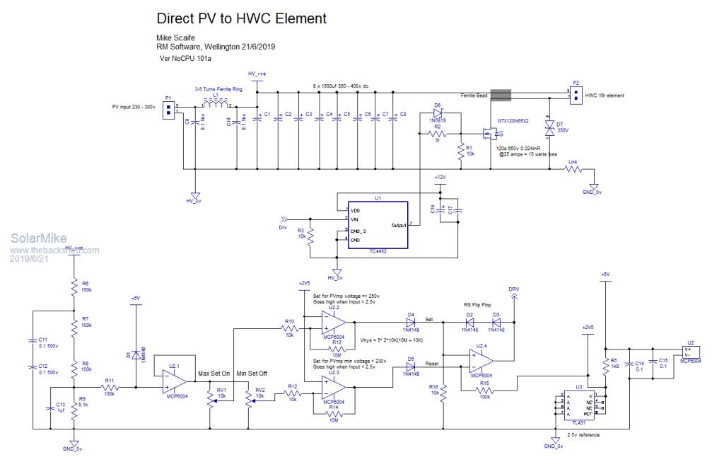 Will make a pcb to test it, helps locate errors in the cct when laying it out. Cheers Mike |
||||
| Warpspeed Guru Joined: 09/08/2007 Location: AustraliaPosts: 4406 |
That is pretty much exactly how I would have done it Mike. The two voltage trip points can be adjusted quite independently, and the whole thing can be set up with nothing more exotic than a multimeter. I have been using some cheaper e-bay high voltage mosfets, at least for initial testing of some prototypes, then used something much better for the final effort. FDA50N50 500v 48 amps 100 or so milliohms. Not exactly state of the art Rdson, but cheap at around $7.15, and it has an absolutely massive silicon die rated for 625 watts. It will run hot, but it will run. https://www.digchip.com/datasheets/parts/datasheet/161/FDA50N50-pdf.php https://www.ebay.com.au/itm/MPN-FDA50N50-Encapsulation-TO-3P-500V-N-Channel-MOSFET-Manufacturer-FAIRCHILD/192950204714?h ash=item2cecba792a:g:E0oAAOSw8w1X~wYX&frcectupt=true Cheers, �Tony. |
||||
| Solar Mike Guru Joined: 08/02/2015 Location: New ZealandPosts: 1123 |
Good choice for initial tests, however if used in final solution, pulsing 24 amps and the expected duty cycle will be dissipating 30 watts or so with Rdson = 100mR. If the Rdson can be lowered to approx 25mR either by a single device or multiples in parallel then so much the better. If the series connected panels max voltage can be lowered somewhat (USA HWC elements are 220v or 115v), then cheaper 300 volt mosfets could be used. I don't have any suitable high voltage PV setup, so for running a test can use a 1KW variable 100v power supply and a 50V DC rated HWC element that I use as a dummy load. Will leave for a few days before looking at the PCB design, so any options or changes people want let me know. Edit: Mosfet diode incorrect, fixed, added status led 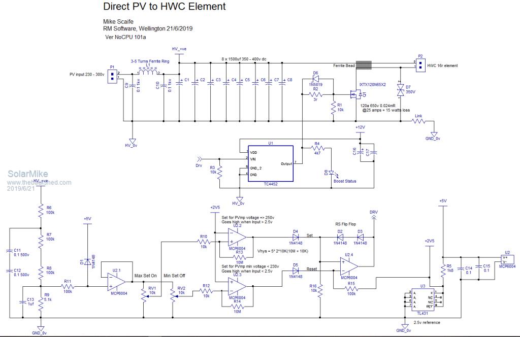 Cheers Mike |
||||
| Warpspeed Guru Joined: 09/08/2007 Location: AustraliaPosts: 4406 |
When I tested that solar panel earlier in my previous post, I only had a very brief patch of clear blue sky to work with, and had to work very quickly. The figures on my power meter were jumping around all over the place, and I now realize why. My 555 runs at only a few hundred Hz, and the voltage on the electrolytic is ramping up and down at that rate. Not by much, but the A/D converter in the power meter is not synchronous with this ramping, and I was seeing scrambled numbers that I had to quickly eyeball, guess, and write down. Anyhow, the test tells us that we have a surprisingly flat power curve, which is what I vaguely remembered from similar testing a few years back. I just wanted to see all that again, and confirm that Mike's circuit is not only workable, but is going to be non critical to set up and also a lot more overall efficient than I expected for something so simple. Cheers, �Tony. |
||||
| Tinker Guru Joined: 07/11/2007 Location: AustraliaPosts: 1904 |
So, if I were to build such a clever solar panel power tester, what should I do different? Run the 555 at a lower frequency? Or fit a bigger capacitor? I happen to have such a Turningy power meter, sitting on my shelf for a long time, waiting for a project  Klaus |
||||
Ralph2k6 Senior Member Joined: 24/09/2017 Location: AustraliaPosts: 129 |
Sorry for my naivety, but is this sort of voltage and power closing in on IGBT's instead of MOSFETS ? rs compnents igbt module Ralph |
||||
| Solar Mike Guru Joined: 08/02/2015 Location: New ZealandPosts: 1123 |
Cannot believe how many errors I made drawing the schematic, the inverting comparator was not going to work... not enough coffee, amended part here. 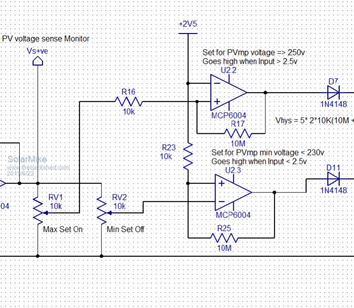 I will start a new thread for this circuit with a replacement drawing.. Mike |
||||
| Solar Mike Guru Joined: 08/02/2015 Location: New ZealandPosts: 1123 |
IGBT's are more robust and less expensive than High Voltage mosfets, and suited for low frequency switching as per this circuit. Their saturation voltage at any appreciable current is approx 2 volts. In this instance the mosfet is switching 15 amps from the charged cap + 8.3 amps from the PV; say 24 amps. The IGBT will dissipate 48 watts, a single mosfet with 24 mR will dissipate 13.8w, 2 parallel mosfets total dissipation = 7 watts. As this is a somewhat lethal device, it has to be placed in an enclosed box, 7 watts heat is easier to control than 48. Cheers Mike |
||||
