
|
|
Forum Index : Electronics : Mack-OffGrid’s 26.5 Volt Warpverter
| Page 1 of 4 |
|||||
| Author | Message | ||||
mackoffgrid Guru Joined: 13/03/2017 Location: AustraliaPosts: 460 |
Thanks Tony for all your patience, unrestricted knowledge and well written posts. This is my first WarpVerter. This inverter is my proving and learning platform for Tony's Warpverter (I have previously called it a Cascade Inverter). This inverter may seem huge but this is partly because at 26.5 volts the current necessitates a lot of FETs. FET count = 40. AS a learning machine I wanted it somewhat roomy to make it easy to work on. It also fits into place ok. 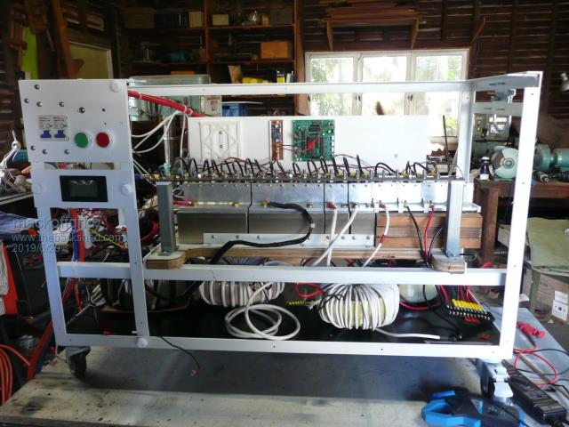 The Inverter Module just sits on slides, disconnect the transformers, power and she just lifts out. 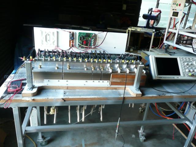 and the inverter-less chassis. 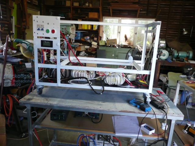 Why 26.5 Volts I have two sites on my Bush Block which we lovingly call the farm. If Gum trees are a crop then its a farm  . The second site is the house site, it just doesn't have a house yet. It does have sheds though. The first site is the Cabin which does have 10kW of solar panels, 8x 320 Ah Li Winston batteries, and a 3kw Latronics inverter which we installed 7 years ago. We went for 24v because at the time there was a lot of cheap 24v inverters which we used as a secondary unit. If I was installing it today I'd naturally go 48v. (I'm going 100v for the house site). I built the solar controller my self and can handle the full 10kWatts if it needs too. Every day, the solar controller charges the battery up at 80Amps until 27.8v where it ramps down in current until it kisses 28 volts. It then allows the batteries to drift down but then maintains a float of 27 volts. So If I turn on the electric jug, it'll draw about 80 amps, the solar controller will match this and keep the battery at 27 volts, and so on. Having a second Inverter means I can run the outdoor water pump or the electric hotwater while using the electric kettle or air conditioning on the inside. If the solar power is there then the controller will provide it. . The second site is the house site, it just doesn't have a house yet. It does have sheds though. The first site is the Cabin which does have 10kW of solar panels, 8x 320 Ah Li Winston batteries, and a 3kw Latronics inverter which we installed 7 years ago. We went for 24v because at the time there was a lot of cheap 24v inverters which we used as a secondary unit. If I was installing it today I'd naturally go 48v. (I'm going 100v for the house site). I built the solar controller my self and can handle the full 10kWatts if it needs too. Every day, the solar controller charges the battery up at 80Amps until 27.8v where it ramps down in current until it kisses 28 volts. It then allows the batteries to drift down but then maintains a float of 27 volts. So If I turn on the electric jug, it'll draw about 80 amps, the solar controller will match this and keep the battery at 27 volts, and so on. Having a second Inverter means I can run the outdoor water pump or the electric hotwater while using the electric kettle or air conditioning on the inside. If the solar power is there then the controller will provide it.So what happens it that the battery sits at 27volts most off the day and if its cloudy it may go down to 26.5 but thats about it. Overnight it will run down to the low 26's and if I put the kettle on it before the sun gets going It will load down to 25.8 volts. So when designing the transformer, I figured I may as well set the minimum battery voltage to 26.5 volts since it is there or above for 98% of the working day, of the year. I don't care if the AC voltage sags during the night. And Just to see a scope shot this is the output at 480 watts, my 2 gell cells sagged to 24 volts and the el-cheapo immersion heater from you know where started to melt - scratch one heater. I don't have fans yet, the heat sink was still cold. 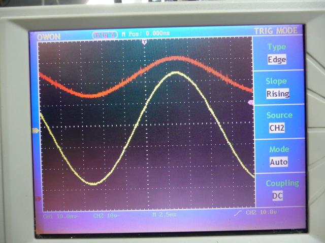 The AC output is the yellow trace (1/11 divider) and the orange is the current clamp on the 2nd transformer leg from the inverter (1mV/Amp) next ... Inverter Module cheers Andrew |
||||
| Warpspeed Guru Joined: 09/08/2007 Location: AustraliaPosts: 4406 |
Great idea making the inverter completely removable. There will be only eight largish wires to disconnect between the four transformer primaries and the inverter, which makes the whole concept very practical. Cheers, �Tony. |
||||
renewableMark Guru Joined: 09/12/2017 Location: AustraliaPosts: 1678 |
Don't make it look too nice, someone will pinch it. You could almost fit a stripper in there. Cheers Caveman Mark Off grid eastern Melb |
||||
| mackoffgrid Guru Joined: 13/03/2017 Location: AustraliaPosts: 460 |
They'll need 2 blokes  |
||||
| Warpspeed Guru Joined: 09/08/2007 Location: AustraliaPosts: 4406 |
Yes indeed ! Cheers, �Tony. |
||||
| Tinker Guru Joined: 07/11/2007 Location: AustraliaPosts: 1904 |
Nice! I hope mine will end up to be just half that size  . There is room in your enclosure for a proper coffee machine behind the front panel and a spare parts drawer at left bottom . There is room in your enclosure for a proper coffee machine behind the front panel and a spare parts drawer at left bottom  . .What is that angle frame made of, painted steel or alu? Klaus |
||||
| arthur8 Regular Member Joined: 08/05/2019 Location: BrazilPosts: 69 |
I really want to try this inverter soon. Also, very nice work! |
||||
| mackoffgrid Guru Joined: 13/03/2017 Location: AustraliaPosts: 460 |
I'm sure it will.Yes, its painted steel angle. There is a little more to the chassis that I'll show later. |
||||
| mackoffgrid Guru Joined: 13/03/2017 Location: AustraliaPosts: 460 |
Thanks Arthur, Heed Klaus's warnings, Transformer winding and coil winding is not much fun. But overall I've really enjoyed this project. Enjoy. Andrew |
||||
| mackoffgrid Guru Joined: 13/03/2017 Location: AustraliaPosts: 460 |
Inverter Module The heart of the Inverter module is the assembly of all the individual bridge board, be it half or full bridge boards. 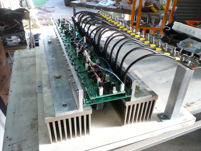 The bridge boards / FET boards (driver boards loaded on top), are nestled between heatsinks on either side. I'll show more on the FET and driver boards in another post. In the photo above, The positive Battery Rail is the left hand "aluminium Angle - heatsink assembly" and extends the full length of the inverter module. (When mounted into the chasis, this positive rail is towards the back.) As with the Ozinverters, the Fets and Fet board makes its +ve connection via the back tabs of the FETS. The Heatsink was drilled and tapped for 8mm bolts to allow the aluminium Angle (50x50x6) to be fastened and also provides multiple battery lead connections. Brass bolts and washers were used. The aluminium angle is ~ 576 mm2, so it is sufficient to use as the buss bar by itself. I believe it has enough bulk to sink heat from the Fets and transfer it to the heatsink. On the right, the "Aluminium angle - Heatsink assemblies" are cut into sections to provide connections for the individual transformer legs. The sections for the two larger transformers had the heatsink part drilled and tapped to take 8mm brass bolts. The sections for the two smaller transformer had the Aluminium angle drilled and tapped for 6mm bolts. Fet-Aluminium angle connections were made by simply drilling a 3mm clearance hole into the Aluminium angle and using stainless 3mm nut and bolt. On the far right is the negative buss bar, nickel plated copper 25x3mm. The first hole is the negative battery connection. Since this photo, a 8mm brass stud has been screwed into position and soldered to the buss bar. The negative connection to the Fet boards is via all those 4mm2 black wires. 4 wires per board, 6 Fet boards. So a total of 96mm2 by 150mm wire is making the negative connection to the FET boards. The connection to the buss is by a 6mm tapped hole and using stainless bolts screwed in firmly from underneath to effect a stud. I did consider using a buss bar on the underneath of the Fet boards but I already have capacitors underneath to dodge, heatsink nearby, and I was worried about the method of fixing to the buss bar so I used the wire approach, more work, not quite as good electrically, but simple. The direct connection to buss bar would be a more optimum method. BTW, The negative buss bar is electrically isolated from those steel RHS stands. You can just notice the capacitor underneath the Fet board. These are distributed all the way along the module. I've used 7 x 22,000uF,2 x 15,000uF, 1x 10,000uF capacitors each with about 6-7 amps ripple current rating. This amounts to 194,000uF and about 60+ amps ripple current rating. The heatsinks was made by ripping one of those big 3kW Aerosharp heatsinks down the middle. 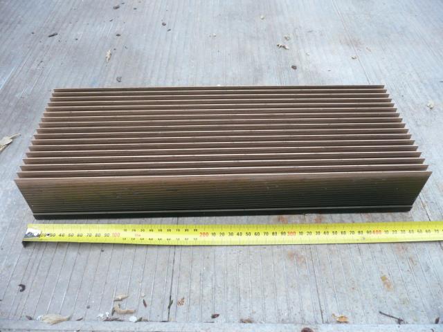 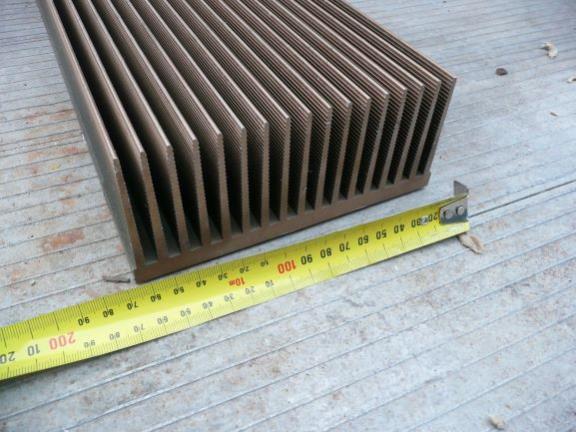 In this photo you can see the Angle-heatsink assemblies cut into sections for the transformer Leg sections. Also note that the Aerosharp heatsink does NOT go the full length of the Inverter module. I deemed that the Angle was sufficiently large to act alone as heatsink for the Fet boards driving the two smallest transformers. Each Fet board is 100mmx100mm, so the Inverter module is just over 600mm wide. The main transformer is driven by three Fet boards. The middle of the three is a full bridge board and on either side are configured as half bridge boards. The second largest is driven by one Fet board, and the two smallest are driven by Fet boards with just one Fet per quadrant. This probably shown the best in the bottom photo. 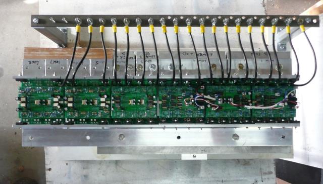 The base board is just plywood. The Heatsinks are attached by plastic angle and self tapping screws. This works well as it give a little bit of flex when fitting the Fet boards. I realise that the orientation of the heatsink is the worst possible orientation. I allowed this as I was more interested in my convenience of assembly and access. Sufficient forced air will fix this sin. A back board is attached (RHS post/bracket) to provide mounting of the control electronics. 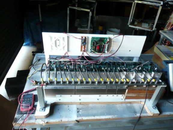 A final note is that Power and Current is distributed fairly well, evenly through the entire inverter section. The smallest Fet board is probably the exception and doesn't work as hard at all. Cheers Andrew |
||||
| Warpspeed Guru Joined: 09/08/2007 Location: AustraliaPosts: 4406 |
That 50mm x 50mm x 6mm angle should work well for you, I have used something similar in various projects with very good results. The electrolytics are going to be a lot more critical working at 24v and at a higher current, rather than at 48v. But the nice clean sine wave output you have, suggests a nice clean dc supply, so its all coming together really well. The small steps are all very even, your transformer voltage ratios are perfect ! Those heat sinks are enormous, and I bet are going to run stone cold most of the time. Excellent job there Andrew. Cheers, �Tony. |
||||
| mackoffgrid Guru Joined: 13/03/2017 Location: AustraliaPosts: 460 |
Thanks Tony Yes, 24volts is the worst possible size for this Inverter (well I suppose 12v is). Double the currents, much more susceptible to voltage drop and on... But all good. Cheers Andrew |
||||
| renewableMark Guru Joined: 09/12/2017 Location: AustraliaPosts: 1678 |
This heatsink layout fitted vertically would cool itself better and would also suit my locker plan. The loose heatsinks would need to be screwed to a non conductive material, much the same as we do with the Oz/Madinverters. Cheers Caveman Mark Off grid eastern Melb |
||||
| Warpspeed Guru Joined: 09/08/2007 Location: AustraliaPosts: 4406 |
For mounting insulated heat sinks, or any general purpose electrical construction you can get fiberglass angle, its called "pultrided angle" and its available from any of the large electrical wholesalers like Marlowes or Middendorp. I use a fair bit of 25mm x 25mm x 3mm fiberglass angle, its really strong and very easy to cut and drill. The stuff I use looks like the smallest size on the right of the picture. 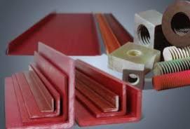 Another way to do it might be to use nylon nuts and bolts (e-bay) and a thin insulating layer or spacer. https://www.ebay.com.au/itm/M8-Nylon-Plastic-Bolts-and-Nuts-and-Nylon-Flat-Washers-Packs-of-6-12-24/283348793190?hash=it em41f8e77766:m:mA7HJWdQVuhcCechbjVuYVA Cheers, �Tony. |
||||
| Tinker Guru Joined: 07/11/2007 Location: AustraliaPosts: 1904 |
Thanks for that detailed description Andrew, my head was spinning for a while trying to figure out how you mechanically mounted those many heat sinks. Plywood you wrote did the job, I suppose you sealed it with something? You win the hole drilling & tapping competition BTW. I gave up counting when I got close to the hundredth hole but your design passes that by a long way .I too use a single 3KW Aerosharp heat sink, I like those and still have two spare. But there are only two non power carrying sections used, I hope the mosfets on insulator washers will survive. I did order a Megger tester to make sure they are insulated to 250v. I do not use brass screws for connections, they are expensive and conduct only marginally better than plated steel bolts. If the bolt just has to clamp the busbar & cable lug together then its current carrying capacity is not an issue. To connect my existing ozinverters to the battery I made 12mm copper bolt thru plastic panel connections with brass washers & nuts - was in for a big surprise at the price of 12mm brass hardware. So for the warpinverter I plan to use 175A Andersen connectors, have some on my shelf. If that is successful my other big inverter will be converted to these so, as a spare unit, it can be connected very quickly. I also plan to install one of these red key High Amp switches with its two connecting bolts bypassed by a suitable big resistor (47R/10W) so, when the key is removed, the big caps can only charge slowly through that resistor. An indicator (LED?) on the panel will tell me when its safe to insert the key and start the inverter up. I will also fit a 10K bleed resistor across the caps so I'm not in for a surprise by the charge left in them from the previous day's testing. When the inverter is put in service that resistor will be switched out. What are you doing in that respect? Klaus |
||||
| mackoffgrid Guru Joined: 13/03/2017 Location: AustraliaPosts: 460 |
Well I was shooting for that Got the T-shirt |
||||
| mackoffgrid Guru Joined: 13/03/2017 Location: AustraliaPosts: 460 |
It was an piece of ply that already had a laminex finish. If it was bare wood and I want a quick seal I often use a clear polyurethane in a spray can. |
||||
| mackoffgrid Guru Joined: 13/03/2017 Location: AustraliaPosts: 460 |
Thanks Tony, I've never heard of "pultrided" material or components. I'll definitely be looking for those in my next project. |
||||
| mackoffgrid Guru Joined: 13/03/2017 Location: AustraliaPosts: 460 |
Klaus, I planned to do a post describing the front panel control but since you asked about the charge / discharge on DC rail. Front Panel - including Charge / Discharge of DC Rail 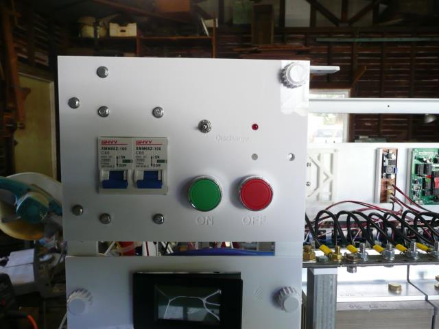 My plan is to do a bit of a schematic to fully explain what I'm doing regarding the front panel controls. I'm also probably going to change it before I'm done. When you have 190,000uF of capacitance hanging on the DC rail I think it's smart if not required to have a pre-charge method. I'd do it on much smaller capacitance because I hate sparks and bangs. It doesn't come out well in this photo but there is a 3 way toggle switch above the Green button. This switch is a ON-OFF-(ON) switch which means it can switch up normally which is ON, middle position is OFF, down position is momentary. I use two of the Aerosharp 33ohm 20 Watt in series, with a bi-directional RED led + 1kR (I think) across the 2x33 ohm resistors. That Red LED you can see on the photo to the right of the toggle switch. The Up position charges the DC rail, this can take a minute. The momentary Down position discharges the DC rail through the same resistor. While we're at it, above the Red Button you can see a pale looking LED. That is a bi-directional Red-Green LED that shows the On-Off status of the inverter. The GReen and Red, On and Off buttons are momentary push buttons. The off button input is quick responding and the On button input is slow responding. If you try pressing both, the Off always over-rides. The two circuit breakers are both 80amp. They are both for positive Battery Feed. I intend to use two 35mm2 cables from the battery, one for each circuit breaker. I have two 35mm2 cables from the circuit breakers connecting to the positive rail of the inverter module spaced to share current. All dual cables are equal length. The negative battery Feed goes directly to the negative rail on the inverter module. I'm not protecting / breaking the negative battery feed because another two breakers would be a pain; I do prefer to use a double pole breaker - isolator, and I will be on the 100v inverter. As the voltage is only 26 volts arcing is not such a problem, I believe it is even legitimate to use AC breakers at this voltage. I will do a little schematic to show some of this front panel stuff later. Cheers Andrew |
||||
| arthur8 Regular Member Joined: 08/05/2019 Location: BrazilPosts: 69 |
Looks nice Andrew. I will be using those three kids on my power board:  For sure i will be soft starting them, like you are doing. Good idea. Also, fantastic work here. Your inverter is a piece of art.  |
||||
| Page 1 of 4 |
|||||
