
|
|
Forum Index : Solar : HWC element powered from HV PV array
| Author | Message | ||||
| Davo99 Guru Joined: 03/06/2019 Location: AustraliaPosts: 1577 |
I thank my preferred Daiety that I do not live in a place like this. Why a society would want to encourage idiots, morons and reward the the shallow end of it's gene pool for it's stupidity, is beyond me. I have seen endless times the safety whinging that makes out peoples personal safety is someone else's responsibility which to a " Normal" person is as laughable as it is Offensive. I would doubt there is anyone here that would even think to blame anyone else if they got zapped tinkering around with what they playing with and the excuse of Ignorance would not wash. The PC leftist Victim mentality push is strong here (as it seems to be around the world) but normal people resist it and push back. I can think of several cases lately where this stupidity has been over thrown as a country rather than just in a specific location. I hope that continues but as we have a nasty track record of copying the most stupid and failed Ideas, I'm sure we will eventually go down the same road. I believe as it stands here, If someone were to connect a devise that was A, non approved by the electrical Authority, and B, BBQed themselves in the process, Then that is on THEM, Not the person they bought it from or anyone else. Perhaps there may need to be a proviso that there had to be something with the unit to say only have it connected by a qualified person if it is legal in your country but I think that would be about it. Approved and installed by a qualified person seems to be the standard here and protects society to a good degree from encouraging and rewarding those that would be better left to the process of natural selection. If I BBq myself, I have no one else to blame. I theory that seems incredulous that anyone should challenge or disagree with that and even more unbelievable that people should support anything else by allowing the stupid to prosper and multiply. |
||||
| Solar Mike Guru Joined: 08/02/2015 Location: New ZealandPosts: 1122 |
OK, the first issue I have is the High voltage isolated sensing of the main capacitor charge voltage, we need to measure changes in this value so the switching points for the mosfets are set. When the dump mosfet turns on the capacitor bank rapidly discharges and drops in voltage; we want about 0.1(RC time constant) duration for a 10 volt change, so the measuring of this has to be quite fast. Seems to be a number of options to do this: 1: Use an optically isolated voltage sense chip like the ACPL-C87B, it has a linear voltage input of 2 volts and a 100 KHz bandwidth. 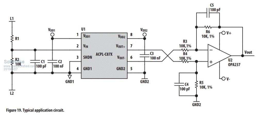 2: Convert the voltage changes to frequency variation, good chip to do this is the AD654 voltage controlled oscillator, it has a linear frequency increase with voltage input, the output square wave can be isolated by an opto-coupler; the only BUT here is a CPU on the other side has to measure the frequency and convert this to voltage trip points. 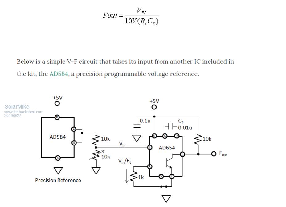 3: Convert the voltage changes to Pulse width , ie 1volt = 10us pulse, 100v = 1msec, 200v = 2ms etc, the pulse can be isolated by the opto coupler and decoded direct by a CPU. #1 seems easiest to use, the output is a dc voltage that can supply the adjustable comparators, #2,3 would bypass the comparators and decisions made by a control CPU. Depends whether a CPU in the mix is desired.... Cheers Mike |
||||
| Warpspeed Guru Joined: 09/08/2007 Location: AustraliaPosts: 4406 |
It all seems very complicated Mike. Why not just a simple voltage divider and comparator ? Cheers, ĀTony. |
||||
LadyN Guru Joined: 26/01/2019 Location: United StatesPosts: 408 |
I too had considered a complicated setup like Mike's but using a V2F convertor (close to option 3 but instead of DC modulation, it would use freq.) because I wanted the ability to dynamically change the set points. A voltage divider would "hardcode" the set point. I dont know whether Mike did it because of the same reason. |
||||
| Solar Mike Guru Joined: 08/02/2015 Location: New ZealandPosts: 1122 |
I wanted complete isolation between the control section and high voltage power, an adjustable voltage divider \ comparator on the high voltage side does not provide any isolation. Current measurement isolation is easy use a ACS758-50U instead of the resistor shunt. I also want to know what the DC voltage is so the output power can be tracked and displayed to the user. And in the back of my mind is, if we know the instantaneous capacitor voltage and discharge current; ie power, then why have any fixed switch points at all - ergo mppt control - vary the switching pulse width at a fixed frequency to get max power into the element. If a cpu is in the mix for user display then why not use it for other things. Mike |
||||
| Warpspeed Guru Joined: 09/08/2007 Location: AustraliaPosts: 4406 |
Not with a potentiometer. Cheers, ĀTony. |
||||
| Warpspeed Guru Joined: 09/08/2007 Location: AustraliaPosts: 4406 |
All this needs is a suitably rated high voltage plug on the solar panel end. Another suitably rated high voltage plug on the heating element end. All fitted into a fully enclosed IP57 plastic housing. Any adjustment potentiometers can have a plastic shaft, and a plastic knob, just like all the commercial 230v light dimmers are required to have. Any necessary countersunk screw heads on the outside of the enclosure can be plastic. Totally enclosed and double insulated. Cheers, ĀTony. |
||||
| Warpspeed Guru Joined: 09/08/2007 Location: AustraliaPosts: 4406 |
You can buy knobs with numbers on them: 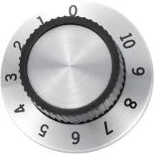 For a system with a 230 volt heating element we could have the numbers on the knob correspond to 0=200v and 10=300v and scale a voltage divider to give us that range. Eight 24v solar panels might have the maximum power point roughly in the 30v to 32v range per panel. That corresponds to 240v and 256v for the max power voltage. That would be around four and five point six around the middle of the knob range. You can then tweak the set points above and below that over roughly a +/- 50v range. The previous test I did suggested +/-5v per panel set points only lose about 7% of maximum power at the peak. With eight panels that might be +/-40v. I don't think we would need to go much wider than that, so a +/-50v adjustment range should do us quite nicely. In fact closer set points should raise the efficiency, but not by very much. The system will also then cycle faster, especially if the electrolytic is on the small side. Here are some suggested resistor values for a 200v to 300v control system using Mike's original circuit. 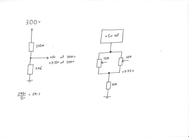 Cheers, ĀTony. |
||||
| Solar Mike Guru Joined: 08/02/2015 Location: New ZealandPosts: 1122 |
Thanks Tony for you input and calculations, Yes insulated Pots with everything mounted inside a plastic case would be safe, not sure about remote temperature sensors, they would have to be well insulated but still be receptive to changes in temperature. I was thinking about the manual adjustment process, as the element load is a fixed resistance, if the integral over time "didt" of the current into the load was done by a small 8 pin cpu, it could automatically adjust the on\off ratio at a constant frequency for max I^2*R average power from the electrolytic bank. I don't need to measure the voltage at all, negating the requirement for pots and comparators. As for the user, all they would have to do is plug it in.... Cheers Mike |
||||
| Warpspeed Guru Joined: 09/08/2007 Location: AustraliaPosts: 4406 |
I suppose it depends on personal philosophy. I see this as a simple, minimum parts project, that with a little help the average guy can successfully build it himself on the kitchen table. If it is built from common simple parts like op amps, logic gates and a few mosfets, its easy to understand how it works, and possible to repair fairly easily years or decades into the future. The problem with using any microcontroller in a project like this, is that its all jolly good fun for the guy that designed it originally, but for anyone else, it becomes essentially unrepairable if it ever stops working. Cheers, ĀTony. |
||||
| Solar Mike Guru Joined: 08/02/2015 Location: New ZealandPosts: 1122 |
That's always the problem, move with updated technology or not; will try to pick something in between. I like to modularize stuff, be it software or hardware design into re-usable components; so have made a start on the pcb design for this project. First up is a simple High voltage switch module, using opto mosfet driver and an isolated 12-12 volt psu, Have allowed for two parallel mosfets, switching rates will be around the 50 - 100 hz so design is simplified somewhat. This module can be connected to the main dump capacitors and a driver to power the element. Sorry about the smd components, don't use anything else for low power stuff... One of the things I would like to experiment with, is to make a full bridge using 4 of these modules and allow the polarity of the HWC element be switched to further prevent arc's forming on the thermostat contacts. I fear if the on duty cycle gets too large using a single mosfet switching the element, then there won't be enough time when the switch is off to suppress an arc. 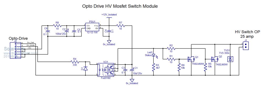 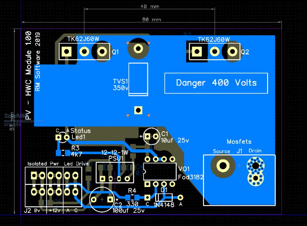 Cheers Mike |
||||
| Davo99 Guru Joined: 03/06/2019 Location: AustraliaPosts: 1577 |
That's what I'm looking for!  I don't need to know when it is on or off, I don't need to know the temp of the water, how much power is being used or generated or anything else. No one knows that with a normal HWS anyway so not like it would be any disadvantage. |
||||
| Warpspeed Guru Joined: 09/08/2007 Location: AustraliaPosts: 4406 |
Davo, Mike's original circuit uses a pair of voltage comparators and a flip flop to switch a mosfet on and off. That is really all that we require. Thinking about all this, a light bulb came on in my head that the popular hobby LM555 chip uses two voltage comparators and a flip flop That will work, but the LM555 output goes logic low when on, and logic high when off. So we require a second chip to invert the gate drive to the mosfet. One other requirement is that at sunrise and sunset, the system will go through a miserable state of being starved for power and probably operating very erratically. So it must have a proper under voltage shut down system to ensure the system starts up and shuts down very cleanly without the risk of frying our mosfet in the half on condition. So I looked around for an inverting mosfet gate driver chip that has under voltage shutdown and could not find one. Then another idea... Many of the opto isolated gate drivers such as HCPL3120 or the FOD3182 that Mike prefers, have under voltage shut down built in. Looking back at my testing of a single 200 watt panel, threshold voltages of 26v and 36v seemed appropriate for that, and I bread boarded this: 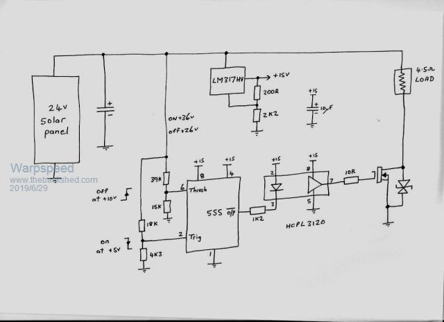 The only change to the above circuit to make a "full power version" would be the resistors that set the voltage thresholds, a suitable small Chinese +15v (0r +12v) dc power supply, and a few more mosfets. Its fairly primitive with absolutely minimal parts, but all the essentials are there. Cheers, ĀTony. |
||||
| Davo99 Guru Joined: 03/06/2019 Location: AustraliaPosts: 1577 |
By full power I take it you mean 230V or say 1000+ watts? |
||||
| Warpspeed Guru Joined: 09/08/2007 Location: AustraliaPosts: 4406 |
Yes exactly. The above circuit is for a single 24 solar panel just as a basic prototype to test the whole circuit concept. Something more practical would be more like eight 24v 250 watt panels in series (2Kw) with a 2Kw or 3.6Kw 230v heating element. I will never build or test anything like that myself. But the problem interests me, and I can throw something quickly together with parts I already have here, but it will only be with one small 200 watt solar panel. Cheers, ĀTony. |
||||
| Solar Mike Guru Joined: 08/02/2015 Location: New ZealandPosts: 1122 |
Good one Tony, a 555 does indeed have the 2 comparators that switch at 1/3/... 2/3 supply voltage. You could use it to drive the power module directly if no bells nor whistles were a requirement. Personally I would want an over temp sensing of the HWC to provide a fail safe plan B should the existing thermostat fail and to switch off prior to the thermostat to possibly prevent contact burn out. My secondary HWc thermostat + element costs approx $300, I want to protect it. If anyone wants to make the power mosfet board here are the gerbers. 2019-06-29_195036_Gerbers_PowerModule101.zip Mike |
||||
| Warpspeed Guru Joined: 09/08/2007 Location: AustraliaPosts: 4406 |
If this was for a professionally designed commercial product, my design would be much more in line with your own way of thinking Mike. That is a whole different ball game. But as a do it yourself project for the novice, it needs to be bare bones simple, with the absolute minimum number of basic parts. Equipment coming out of China is now so low cost, it really makes home constructing a great many things just not worth the trouble. For instance, you could buy a very nice digital temperature readout with sensor, and programmable alarm relays for under and over temperature, that could provide thermostat backup for probably less than $30. Cheers, ĀTony. |
||||
| Warpspeed Guru Joined: 09/08/2007 Location: AustraliaPosts: 4406 |
Connected it all up and it works exactly as expected. With 15,000uF and a 4.5 ohm load it cycles at around 7.8Hz in clear sun with a long discharge time. With a 2 ohm load and 15,000uF its about 25Hz, and charge/discharge times are much more even. That is probably more like how it might look with eight panels in series and a 16 ohm load. In full shade it slows right down to less than 1Hz, but its still pumping power. Mike's estimate of 10,000uF looks to be right on the money. This all looks very encouraging !!!!!!! I have been using two radiator bars as a load out in the shed, and they get quite nicely warm with about 160 estimated watts, hot smells and all. Which gives me another idea. Something like this could also be used for some low grade winter heating of rooms or buildings on the shade side of the house. Its quite good, because it keeps the solar panels operating in their most efficient region. A cloud rolls by and it just slows down, but the voltage on the panels stays in the exact same optimum range. Cheers, ĀTony. |
||||
| Solar Mike Guru Joined: 08/02/2015 Location: New ZealandPosts: 1122 |
Excellent, trouble is 10,000uf at 350-400 volts with ripple rating 15-20 amps doesn't come cheap; people will have to be inventive and find quality caps from old power supplies etc. Mike |
||||
| Warpspeed Guru Joined: 09/08/2007 Location: AustraliaPosts: 4406 |
No real reason why it cannot be allowed cycle much faster. But I agree, that a suitably high ripple current rating is essential if the electrolytics are going to be long term reliable. Cheers, ĀTony. |
||||
