
|
|
Forum Index : Solar : HWC element powered from HV PV array
| Author | Message | ||||
| Warpspeed Guru Joined: 09/08/2007 Location: AustraliaPosts: 4406 |
I had a couple of Weller irons with burned out elements. Radio Parts have the elements: https://www.radioparts.com.au/product/38575296/he60-24v-heating-element-weller-for-tc201#.XS0nTvwRU5k Cheers, ĀTony. |
||||
| Warpspeed Guru Joined: 09/08/2007 Location: AustraliaPosts: 4406 |
Yes. Cheers, ĀTony. |
||||
| isochronic Guru Joined: 21/01/2012 Location: AustraliaPosts: 689 |
Thanks .. Wish I'd known that ...  |
||||
| Solar Mike Guru Joined: 08/02/2015 Location: New ZealandPosts: 1122 |
Have completed the driver pcb that allows me to experiment with either full mppt control of the PV to HWC using an H-Bridge or a single mosfet switch, (drive the mosfet opto power module a few posts back. The CPU side is fully isolated from the High voltages so I can experiment and not blow up any of my test gear, or get zapped. Its certainly more complex than the basic 555 timer version, with LCD screen, current and temperature sensors etc. but not alarmingly so. 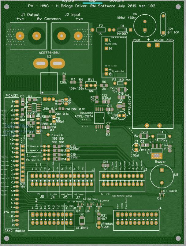 Cheers Mike |
||||
| Solar Mike Guru Joined: 08/02/2015 Location: New ZealandPosts: 1122 |
Here is the basic 555 timer version, for those interested. The 100x100mm PCB has provision for up to 3 mosfets, so depending on their on resistance specs, extra's can be added to get the losses down. The schematic has a few extra bits added compared to Warps cut down circuit, any surface mount components used have been overlayed by through hole foot prints to make it easier to build. 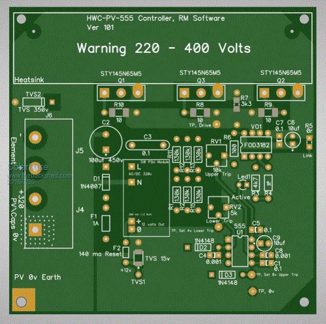 Circuit: 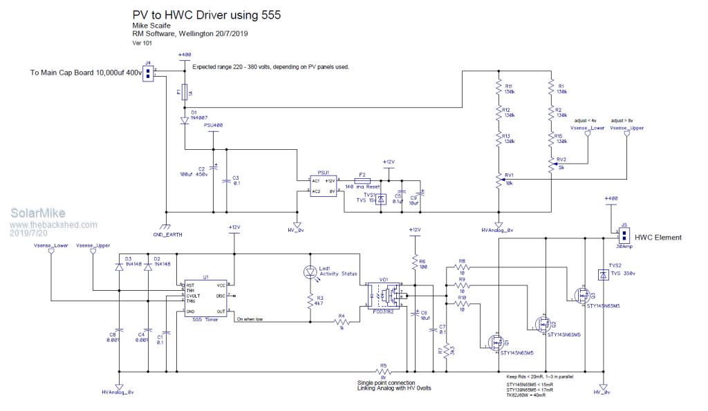 Pdf Circuit: 2019-07-20_143707_PV_HWC_555Timer.pdf Gerbers: 2019-07-20_143842_Gerbers_HWC_555Timer.zip, drop the pdf file on JLCPCB Quote Page to see the pcb. The tiny edge mounted 12v power supply used available Here I also have a very similar version that uses a Picaxe 08M2 to replace the 555, this allows a simple mppt algorithm to be used, will post that later... Cheers Mike |
||||
| Solar Mike Guru Joined: 08/02/2015 Location: New ZealandPosts: 1122 |
Thought I would try using a picaxe 08M2 cpu running at 32 Mhz in the basic circuit rather than the 555 timer, and implement a simple mppt algorithm to extract max power from the PV array. Because the HWC element is essentially a fixed load, max power can be calculated by timing how long it takes for the array caps to discharge between two voltage points; so If I take the average voltage and multiply against dt (discharge Time) the highest value will be the max power point. The CPU can continually change the discharge dump time into the element to locate and maintain max power transfer... That's the theory anyway, as the process with 10,000 uf or so is quite long ie 10's mSec to discharge, the picaxe basic although not that fast should be able to cope, will see. PCB: 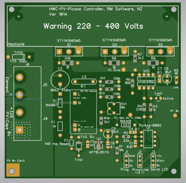 Gerbers: 2019-07-20_152024_Gerbers_HWC_Picaxe08M2.zip , drop this file on JLCPBC Quote Page to See Circuit: 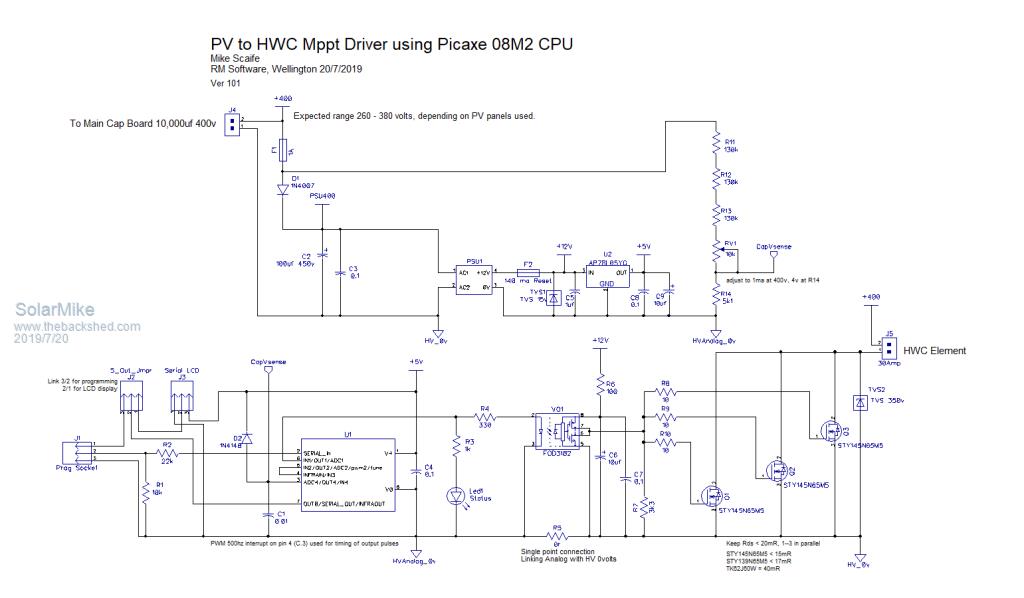 Pdf: 2019-07-20_152125_Circuit.pdf I haven't written any software for this, currently getting together a large batch of pcb's to be made from many projects; will write some code and post it here when I get the boards back; picaxe basic is about as simple as it gets, so with luck anyone here could successfully play with it. Cheers Mike |
||||
| Warpspeed Guru Joined: 09/08/2007 Location: AustraliaPosts: 4406 |
That is a very nice board Mike ! The few extra parts are all small low cost items, so why not ? Its basically the same identical circuit. Cheers, ĀTony. |
||||
| Solar Mike Guru Joined: 08/02/2015 Location: New ZealandPosts: 1122 |
Thanks, figured as I had already completed the Picaxe 08M2 version (one I will be actually building), it was a minor alteration to duplicate and put in the 555 bits, for the forum. I haven't produced a parts list, self explanatory really; the big 25 amp 4 pin connector has 10mm pin spacing and available on AliExpress; cheaper STY145N65M5 mosfets there as well, dont know If I would trust them though, thus the allowance for 3 in parallel. Cheers Mike |
||||
| Warpspeed Guru Joined: 09/08/2007 Location: AustraliaPosts: 4406 |
I tend to use the cheapies when prototyping and initially messing about. They run rather hot, and that would be a bit of a worry for long term reliability. But once the rest of the circuit has been sorted out, I can then fit the much more expensive low Rdson parts with more confidence. Cheers, ĀTony. |
||||
