| |
Page 1 of 8   |
| Author |
Message |
Warpspeed
Guru

Joined: 09/08/2007
Location: AustraliaPosts: 4406 |
| Posted: 07:25am 16 Jul 2019 |
 Copy link to clipboard Copy link to clipboard |
 Print this post |
|
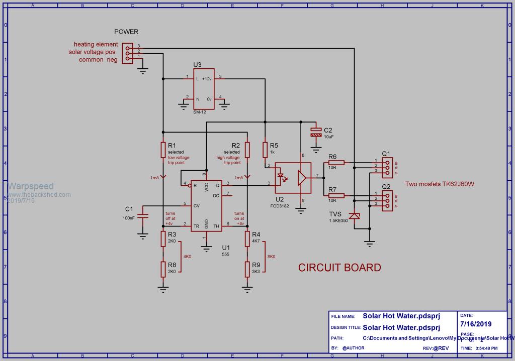
O/k first of all, here are the main wiring diagram and the circuit board schematic.
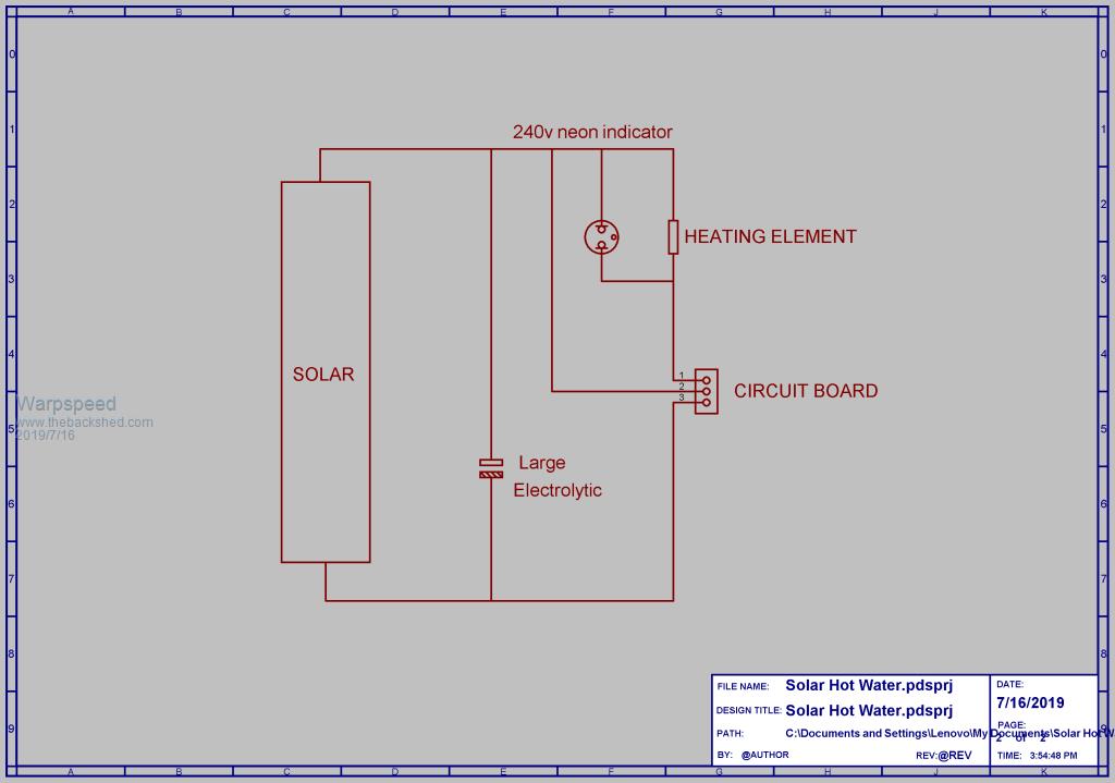
The number of solar panels may vary, but assuming a 220/240v heating element there may be typically eight 24v panels in series.
A large electrolytic will be required possibly around 4,700 uF 350 volts minimum, or at least something that can safely withstand the full no load solar panel voltage.
The circuit will cycle faster with a lower capacitance and more slowly with a higher capacitance. So the actual value is not that critical.
A 230v neon indicator will flash on briefly during each discharge part of the cycle to show that all is well.
The two resistors R1 and R2 should be one watt carbon resistors which are physically larger than the usual small metal film resistors, to ensure they both have a sufficiently safe voltage rating.
A small Chinese postage stamp sized 12v dc power supply provides power.
The voltage switching thresholds of the 555 will be 1/3 (4v) and 2/3 (8v) of the dc supply voltage.
There are two voltage dividers that set the switching thresholds, and the 555 will switch when the current flowing through R1 and R2 each crosses one milliamp.
This makes resistor selection much easier.
So the low threshold voltage when the heating element turns off will be four volts plus R1 value in K ohms.
The high threshold where the heating element turns back on will be eight volts plus the value of R2 in K ohms.
These voltage thresholds are not ultra critical so the nearest commonly available resistor value will work just fine.
Now for a hypothetical example.
Suppose the rating sticker on one of our solar panels says maximum power at 32 volts.
And we decide to set the heating element turn on upper voltage threshold to 36 volts, and we have eight panels in series.
The upper threshold would be 8 x 36v = 288 volts.
If we subtract 8v from that we get 280v, and theoretically a 280K resistor.
A 270K resistor will be close enough for R2.
For a lower voltage threshold where the heating element is turned off, we might decide 26v is about right.
Lower threshold would be 26v x 8 = 208 volts.
If we subtract 4v from that we get 204v and theoretically 204K resistor.
A 200K resistor would be closest value for R1.
The voltage will be ramping between something like 204v and 278 volts assuming everything is perfect.
Its swinging up and down over a 74 volt range, so a few volts error at either end is really nothing, because the power curve of our panels is flat and very broad.
The power drop off at each end might be something like 10%, and the average over that range could be in the region of 95% of what it is right at the very peak.
Cheers, ĀTony. |
| |
Davo99
Guru
Joined: 03/06/2019
Location: AustraliaPosts: 1577 |
| Posted: 07:37am 16 Jul 2019 |
Copy link to clipboard |
Print this post |
|
Thank you very Much for your efforts Tony. Does my head in how you can just sit down and work something like this out.
I don't know how to build it but I shall try to work it out.
Thanks again, much appreciated. |
| |
mason

Regular Member

Joined: 07/11/2015
Location: CanadaPosts: 86 |
| Posted: 05:47pm 17 Jul 2019 |
Copy link to clipboard |
Print this post |
|
Thanks Warpspeed for the circuit diagram...
Question for you: I have HWT that takes 220 but where I live the mains are split phase
so it takes two 120 feeds, would you build two circuits of half the value or splice the two 120 together at the water heater.. Hope this makes sence ..
Thanks,
|
| |
Warpspeed
Guru
Joined: 09/08/2007
Location: AustraliaPosts: 4406 |
| Posted: 09:43pm 17 Jul 2019 |
Copy link to clipboard |
Print this post |
|
I would use the 220v connection to the elements, but it would work either way.
It only has to discharge the main electrolytic, so within reason the resistance of the heating element is not critical.
The peak current will be less with the elements connected in series, that gives the switching mosfet and its heatsink an easier task.
Cheers, ĀTony. |
| |
mason
Regular Member
Joined: 07/11/2015
Location: CanadaPosts: 86 |
| Posted: 09:50pm 17 Jul 2019 |
Copy link to clipboard |
Print this post |
|
ok thanks a lot Tony I'll do it the 220v way.. |
| |
LadyN

Guru
Joined: 26/01/2019
Location: United StatesPosts: 408 |
| Posted: 06:45pm 24 Jul 2019 |
Copy link to clipboard |
Print this post |
|
This is beautiful.
The neon indicator itself is very helpful debugging aid.
Brilliant!
Time to learn what the 555 is, how it works, etc. Last time I studied a datasheet in details - the TL431, took me a month :(
|
| |
Warpspeed
Guru
Joined: 09/08/2007
Location: AustraliaPosts: 4406 |
| Posted: 11:33pm 24 Jul 2019 |
Copy link to clipboard |
Print this post |
|
Oh you will find plenty of info and applications for the venerable LM555 timer chip.
Its been a hobbyists favorite for small projects for decades.
Cheers, ĀTony. |
| |
Davo99
Guru
Joined: 03/06/2019
Location: AustraliaPosts: 1577 |
| Posted: 10:47am 25 Jul 2019 |
Copy link to clipboard |
Print this post |
|
I got the 6x 1000uf caps off the Inverter board OK which I will put to this project.
Waiting in anticipation for all the components I have ordered to arrive.
I order stuff from china all the time and when I'm in no hurry it's here in sometimes 7 days or less. The stuff I am keen to get always takes the slow boat.
According to the Dodgy fake tracking numbers, some things I ordered landed here 2 weeks ago but still haven't made it from the mail centre to here.
Ya! :0( |
| |
Warpspeed
Guru
Joined: 09/08/2007
Location: AustraliaPosts: 4406 |
| Posted: 10:10pm 25 Jul 2019 |
Copy link to clipboard |
Print this post |
|
Ordering stuff from China is always a bit of a worry.
Will it arrive at all, and if it does, will it actually work ?
The costs are so low though, that I still think its worth the risk.
Cheers, ĀTony. |
| |
sgaede
Newbie

Joined: 27/07/2019
Location: United StatesPosts: 7 |
| Posted: 10:56pm 11 Aug 2019 |
Copy link to clipboard |
Print this post |
|
Warp
Thank you for posting this
Steve |
| |
Warpspeed
Guru
Joined: 09/08/2007
Location: AustraliaPosts: 4406 |
| Posted: 12:14am 12 Aug 2019 |
Copy link to clipboard |
Print this post |
|
Welcome to the Forum Steve.
Cheers, ĀTony. |
| |
Jacob89
Newbie
Joined: 10/09/2017
Location: AustraliaPosts: 39 |
| Posted: 12:15pm 25 Aug 2019 |
Copy link to clipboard |
Print this post |
|
Is there any reason this same circuit couldn't be used to run a DC motor direct from solar? I built a dc pump "optimiser" from a kit that as I understand uses the same principle as this - charges a bank of capacitors to a set voltage, than closes the circuit to the pump motor until the voltage drops again to a certain point. It seems to help keep my small 24v pump running when otherwise it wouldn't if it was directly running on the panels.
I'd like a bigger version though, to run a 190v DC motor from a treadmill directly from solar. This might be the ticket. |
| |
Warpspeed
Guru
Joined: 09/08/2007
Location: AustraliaPosts: 4406 |
| Posted: 09:20pm 25 Aug 2019 |
Copy link to clipboard |
Print this post |
|
In theory yes, but the energy storage capacitor would need to be made much larger to run a motor.
Heat energy can be pumped effectively in very short bursts, so the system can cycle fairly rapidly with a small capacitor and it will work fine.
These short bursts of heat average out due to thermal inertia.
There might be 2Kw lasting for just a few tens of millisecinds for example.
I would think that a pump motor would need to run for at least several seconds at a time to reach working speed, and produce any worthwhile output. So the capacitor storage will need to store a fair chunk of energy. If its for a low voltage motor, some ultracapacitos may be worth considering.
A 190v motor will probably require electrolytics, and rather a lot of them too, which might be fairly costly to get acceptable pump performance.
Cheers, ĀTony. |
| |
Davo99
Guru
Joined: 03/06/2019
Location: AustraliaPosts: 1577 |
| Posted: 03:28am 26 Aug 2019 |
Copy link to clipboard |
Print this post |
|
I see now that windmills have pretty much gone by the wayside and being replaced by these Direct solar Pumps. Same as in India and parts of asia where the " traditional" Lister/ Petter and and Yanmar type Diesel clones are also being replaced with solar.
The gubbermints are subsidising the initial cost but the lack of running costs would seem to make repayment of the investment very worthwhile.
Also in a lot of these places there is no power so having the solar gives the owners the ability to charge batteries or run a cable to their house so they can have Radio, TV and lights with a battery.
I don't know how these work exactly, Judging by the array sizes they don't seem to be 24 or low voltage and on the vids I have seen they seem to kick out plenty of water so must be at least in the 1-2Kw range.
Would seem this controller would be no different to using a VFD or speed controller that runs on PWM which I have a couple of I use.
Just waiting on a couple more components and to finish working on the new Kitchen and I hope to build my controller.
Ironically, one of the ideas I had for the controller turned out to be a bit over estimated.
I put 25L of water in a drum in an old Fridge to provide a thermal mass for raising seedlings. I put 4x 175W panels on a 3.6Kw element. I boiled the water with the sunny days we had so have had to back it off to 2 panels and then it's still probably a bit on the warm side. Think I'll have to add a little thermostat for control.
I saw a few things on the net by a guy that made a controller and was heating 6 gallons of water. That's about 25L so not sure why anyone would go to the trouble of the controller when even such an inefficient system will do the job. Spose it might be different if there was a lot of cloudy weather but you could heat a Lot more water than 6 Gal with a controller in any case.
My holiday house only has a 30L HWS and that barely lasts 1 shower. At least being on mains it re heats in under an hour so not a big problem but I'll certainly replace it with a 125L when it falls over. |
| |
Warpspeed
Guru
Joined: 09/08/2007
Location: AustraliaPosts: 4406 |
| Posted: 03:57am 26 Aug 2019 |
Copy link to clipboard |
Print this post |
|
Where there is plenty of sun, there is no problem driving a pump.
The difficulty is the start up current and maybe priming the pump if its a deep well.
In very heavy overcast the pump may not be able to even start, it will just pull the solar panel voltage down to almost nothing, well below any usable power curve.
So basically nothing at all will be pumped.
If you have a bank of ultracaps and allow them to charge, that might take several minutes. Then hit the pump with that. ĀIt should start but only run for perhaps a few seconds, but at least you will get something.
The more ultracaps, the longer the pump will run for each time, but it also will take correspondingly longer to recharge.
If you need 1Kw to lift water to a fair height, and there is only fifty watts of solar, it will only run for about 1/20th the time it takes to recharge. ĀBut you WILL get your miserable 50 watts worth of water pumped, even if the sky is evil grey for a week.
The VFD method would be much more appropriate for a higher voltage, much higher powered system. But at ultra low turning speed, it may still not develop enough torque to raise water to a sufficient height. Short bursts at near full power may be more effective.
For a really small low power system a 24v or 48v positive displacement pump running intermittently, and some ultracaps and a couple of panels could probably all be done at a tolerably low cost.
Edited 2019-08-26 15:08 by Warpspeed
Cheers, ĀTony. |
| |
mackoffgrid

Guru
Joined: 13/03/2017
Location: AustraliaPosts: 460 |
| Posted: 11:25pm 10 Oct 2019 |
Copy link to clipboard |
Print this post |
|
Hi Tony
Did you ever get PCBs made and test this circuit?
Cheers
Andrew |
| |
Warpspeed
Guru
Joined: 09/08/2007
Location: AustraliaPosts: 4406 |
| Posted: 12:18am 11 Oct 2019 |
Copy link to clipboard |
Print this post |
|
I breadboarded it and bench tested it, but have neither a suitable high voltage solar source, or hot water heater tank to test the whole thing in its final configuration.
I did build a 24v mini version working into a four ohm resistive load, with a single 250W solar panel, and that worked exactly as expected.
No circuit board though.
Cheers, ĀTony. |
| |
Davo99
Guru
Joined: 03/06/2019
Location: AustraliaPosts: 1577 |
| Posted: 01:20am 11 Oct 2019 |
Copy link to clipboard |
Print this post |
|
I kinda got a bit lost on this although it is something I do want to do.
I had at least one component not arrive, I'll just see if I can get them from Jaycar.
My desk has a pile of little boards sitting on it I want to play with as well but right now I'm overwhelmed with some home renos that are not going according to what we wanted.
Solar is really such a fickle animal.
The 3 190/175? ( can't remember) panels I have on the 25L drum are near boiling it on the sunny days. Haven't checked on the cloudy days but then again I wouldn't expect much from any setup in these conditions.
One is just trying to make the most of essential chasing ones tail under those conditions.
Wish you were in Syd Tony. I have plenty of panels I could give you and some heater elements as well. |
| |
Warpspeed
Guru
Joined: 09/08/2007
Location: AustraliaPosts: 4406 |
| Posted: 03:51am 11 Oct 2019 |
Copy link to clipboard |
Print this post |
|
I wish you lived in Melbourne Dave, we think very much alike on so many topics.
Yeah, I built a solar thermal system many years ago, pumped hot water, it was o/k but I doubt if there was much ROI when all said and done.
In mid winter it was pretty useless, and in summer it boiled. I suppose a thermal electric system would pretty much behave the same way.
Natural gas is so cheap here in Melbourne, its just not worth considering anything else for supplying raw heat.
Cheers, ĀTony. |
| |
mackoffgrid
Guru
Joined: 13/03/2017
Location: AustraliaPosts: 460 |
| Posted: 04:45am 11 Oct 2019 |
Copy link to clipboard |
Print this post |
|
I've seen some videos of overly simplistic attempts of running HWS directly from solar panels and they could do with reading this thread. |
| |
| |
Page 1 of 8 |
