
|
|
Forum Index : Microcontroller and PC projects : Hoist Wiring
| Author | Message | ||||
| Phil23 Guru Joined: 27/03/2016 Location: AustraliaPosts: 1667 |
Hi All, I was "Gifted" a lifting hoist that didn't work out of the box & was replaced by the supplier. https://www.kincrome.com.au/lifting-hoist-400-800kgs It's a 400kg bolt to the rafters thingo with a 1300W induction motor. Was passed on to me as the supplier said dispose of it. When I hit the up or down buttons it just makes a clunk & the motor hums. The parts diagram shows a brake disc which I think is what clunk is. Looks like it gets pulled towards the windings to disengage. Drew this rough mud map of the wiring as I suspected that there may be a wire wrong somewhere & not sure about how you wire reversible induction motors. Get the impression that it might be related to how the Starting Cap is wired. 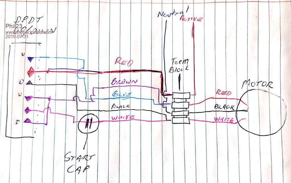 Haven't studied it too hard yet, but any help would be appreciated. Thanks Phil. |
||||
| Phil23 Guru Joined: 27/03/2016 Location: AustraliaPosts: 1667 |
Basically, Once I've traced it out a bit it just looks like this for Up & Down. Wondering now how I identify the winding taps from the motor. 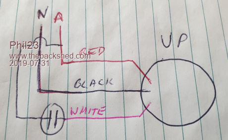 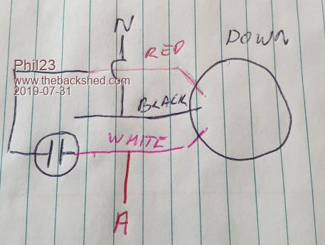 |
||||
| Phil23 Guru Joined: 27/03/2016 Location: AustraliaPosts: 1667 |
Scrap All of the above.... I investigated what I was avoiding & putting at part 2. Mechanical issues... Removed the fan cowl & motor was stuck even with the brake disengaged; Pulled the end of the motor & back on with a bit of grease on the spline & now it works just fine.... Cheers. |
||||
| PeterB Guru Joined: 05/02/2015 Location: AustraliaPosts: 669 |
G'Day Phil That system is typical and clever. It uses a centre tapped winding RED BLACK WHITE. In the UP direction ACTIVE is applied to the RED PHASE and the WHITE PHASE gets a phase shift due to the CAPACITOR. In the DOWN direction ACTIVE is applied to the WHITE PHASE and the RED PHASE gets a phase shift due to the CAPACITOR. The first time you come across it you start to doubt your sanity.  Peter |
||||
| lizby Guru Joined: 17/05/2016 Location: United StatesPosts: 3784 |
For the edification of the idle curious (not that I will ever have a use for the knowledge) can you explain this in a little more detail? PicoMite, Armmite F4, SensorKits, MMBasic Hardware, Games, etc. on FOTS |
||||
palcal Guru Joined: 12/10/2011 Location: AustraliaPosts: 2039 |
I learned this when an apprentice but had forgotten the exact detail so from the internet... "It is better to be ignorant and ask a stupid question than to be plain Stupid and not ask at all" |
||||
| palcal Guru Joined: 12/10/2011 Location: AustraliaPosts: 2039 |
To add to the above it seems as though in Phil's drawing the run and start windings must be similar so in the up direction white is start and in the down direction red is start. "It is better to be ignorant and ask a stupid question than to be plain Stupid and not ask at all" |
||||
| Phil23 Guru Joined: 27/03/2016 Location: AustraliaPosts: 1667 |
Out of interest I did measure the windings & got something like 4.6 & 5.2 Ohms. Maybe the up power is a bit more than the down. Or could be something to do with slowing the decent rate. (If they even thought that hard). |
||||
TassyJim Guru Joined: 07/08/2011 Location: AustraliaPosts: 6538 |
Does this motor have a start winding that cuts out once up to speed like most or is the the type that have both windings in circuit all the time. I think the latter is the one we have here. Not that it maters except when you are looking at the duty cycle of the capacitor. Jim VK7JH MMedit |
||||
| PeterB Guru Joined: 05/02/2015 Location: AustraliaPosts: 669 |
G'Day All All electric motors need a rotating magnetic field. 3 phase motors get it easy because you have 3 voltages 120 degrees apart and when they are connected to 3 cunningly positioned windings you get a beautiful rotating magnetic field. If you then stick a permanent magnet inside the motor it will rotate and that is a synchronous motor. If you stick coils inside and short them out you get a conventional 3 phase motor where torque is proportional to slip up to a point. Now. To get a rotating magnetic field from a single phase supply you have to use reactance. A simple fractional horse power motor has 2 windings. There is a RUN winding and a START winding. The START winding is usually connected via a capacitor which causes a lead in the current. The reason I went to uni. was to understand i = C * dv/dt. That is, the current in a capacitor is proportional to the rate of change of the applied voltage. So, if an AC voltage is applied to a capacitor, the current will be maximum when the voltage is changing at the maximum rate and the current will be minimum when the voltage is not changing. All of that just means that the current in the START winding is out of phase with the RUN winding and we have a (rough) rotating magnetic field. As noted by Jim the start system can be removed once the motor is running however some motors are capacitor start and capacitor run which gets us to this motor. It really is a simple capacitor run, capacitor start motor. The clever bit is having 2 identical windings cunningly arranged to give a rotating magnetic field and then swapping them over to reverse direction. Phil has measured different resistances (the swine) The reason is, WHO KNOWS. I have gone on a bit. sorry. If you need any more just yell. When I become dictator all motors will be 3 phase by law.  Peter |
||||
| SimpleSafeName Guru Joined: 28/07/2019 Location: United StatesPosts: 351 |
It sounds like the brake is designed similar to a Demag motor where the rotor is conical and once power is applied the rotor shifts forward which disengages the brake. We used Demag motors on our lifts at Saturn and the one drawback was that you couldn't use a VFD with these motors. |
||||
| BrianP Senior Member Joined: 30/03/2017 Location: AustraliaPosts: 292 |
PeterB wrote: One winding is quite likely wound on top of the other, so will have many more turns - therefore more ohms...  |
||||
| PeterB Guru Joined: 05/02/2015 Location: AustraliaPosts: 669 |
That is possible but I used the word cunning to describe the windings because I have never been sure how they are arranged. I suspect they are identical and Phil's meter is no good. Only joking  Peter |
||||
| Phil23 Guru Joined: 27/03/2016 Location: AustraliaPosts: 1667 |
Lol, I'm actually very chuffed that my 30+ year old Fluke 77 measures within one digit count of my new Fluke 179. Have another cheapy tossed in a box somewhere that used to live in the car boot. Turned out to be accurate within about +/- 25%. Caught me out once years back when I pointed the finger at a PC power supply that had 3 point something on it's 5V rail. 50k round trip to grab a PS to fix the problem & then it turned out to be just poorly seated RAM. |
||||
| PeterB Guru Joined: 05/02/2015 Location: AustraliaPosts: 669 |
I bought a METEX meter about 30 years ago and there were times when I would wonder if it was reliable. So I bought a FLUKE. I need not have bothered. The METEX is just as accurate. Resistors don't drift like they used to. My introduction to that type of motor was a dumb waiter. A winding had burst into flames probably due to insulation breakdown. Peter |
||||
| The Back Shed's forum code is written, and hosted, in Australia. | © JAQ Software 2026 |
