
|
|
Forum Index : Microcontroller and PC projects : CMM - Extra Diode!?! (Altronics PCB)
| Author | Message | ||||
| Poppy Guru Joined: 25/07/2019 Location: GermanyPosts: 486 |
Hi Everybody. Please compare these 2 pictures of the Colour Maximite: http://geoffg.net/Images/ColourMaximite/06.jpg and http://www.electronicsfun.net/wp-content/uploads/2014/10/DSC_0094_2.jpg What kind of and what is this extra Diode vertically left to the IC2(7805)-Capacitor for? To me not having an Altronics Set this component is surprisingly new.   Andre ... such a GURU? Andre ... such a GURU? | ||||
| twofingers Guru Joined: 02/06/2014 Location: GermanyPosts: 1761 |
Hi, I think it's a 1N5819 (Schottky diode, 40 V, 1 A) that protects the 7805 from "overvoltage" (7805 Out > 7805 In)? But then the 1N5819 cathode should be connected to 7805-Out and the 1N5819 anode to 7805-In. Another case: the 1N5819 is between power an 7805-In (in flow direction) that would protect against reverse polarity. Or the 1N5819 is between 7805-Out and Gnd, that could protect against negative voltages. It is not easy to decide, because the tracks are not visible. Michael Edited 2019-08-07 06:10 by twofingers causality ≠ correlation ≠ coincidence |
||||
palcal Guru Joined: 12/10/2011 Location: AustraliaPosts: 2039 |
It is in series with the output of REG1, I think it has something to do with using USB power. "It is better to be ignorant and ask a stupid question than to be plain Stupid and not ask at all" |
||||
| palcal Guru Joined: 12/10/2011 Location: AustraliaPosts: 2039 |
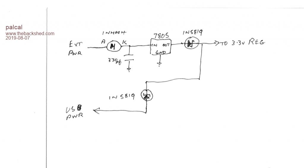 Not good but you get the idea? "It is better to be ignorant and ask a stupid question than to be plain Stupid and not ask at all" |
||||
| twofingers Guru Joined: 02/06/2014 Location: GermanyPosts: 1761 |
ah, it should decouple the two input ways (Ext. Pwr and USB Pwr)! Makes sense! causality ≠ correlation ≠ coincidence |
||||
| palcal Guru Joined: 12/10/2011 Location: AustraliaPosts: 2039 |
It is not really an extra diode, it is on both boards, just a different layout. "It is better to be ignorant and ask a stupid question than to be plain Stupid and not ask at all" |
||||
Chopperp Guru Joined: 03/01/2018 Location: AustraliaPosts: 1126 |
With my CMM, I removed the diode from the USB to the 3v3 Reg & bridged the diode following the 5V reg. It's powered from a 9V power pack & USB is permanently attached to the PC (Which is only on now & then). I wanted a full 5V to drive an TXRX module which was playing up. Not sure if was the lower voltage or just my poor wiring setup, but I do like 5V being 5V. ChopperP |
||||
| Volhout Guru Joined: 05/03/2018 Location: NetherlandsPosts: 5931 |
@poppy: - The diode you refer to protects the 7805 voltage regulator in case USB is powered. - It is in both layouts (only in a different place). The voltage drop across it is some 200-300mV (depending on what is powered from it). Modern designs use a slightly more expensive FET, that virtually zero voltage drop. Volhout Edited 2019-08-07 17:51 by Volhout PicomiteVGA PETSCII ROBOTS |
||||
| Poppy Guru Joined: 25/07/2019 Location: GermanyPosts: 486 |
Hi guys, thanks for your help.  Now after your pass I can read the "1N5819" and I have not recognized up to now that there are even more minor changes in tracks. Apparently it is D2, though we do only have a top view, so this all makes sense to me now. 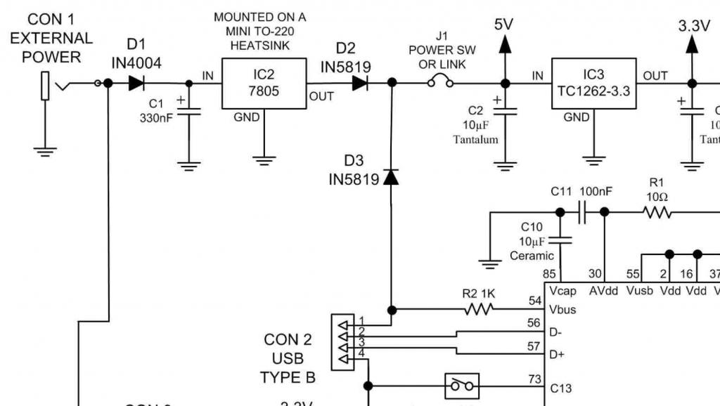 Andre ... such a GURU? Andre ... such a GURU? | ||||
| CaptainBoing Guru Joined: 07/09/2016 Location: United KingdomPosts: 2171 |
they allow the device to be run from either USB power or via the DC input jack and 7805. The diode on each power source blocks power from the other source being fed back through it... and the large currents that would likely flow |
||||
| Poppy Guru Joined: 25/07/2019 Location: GermanyPosts: 486 |
Thanks! Currently I am just powering my CMM through the USB by an diy USB-A to USB-B-Cable, very flexible and a common USB-Power-Adaptor. This works best for me not getting anything hot. 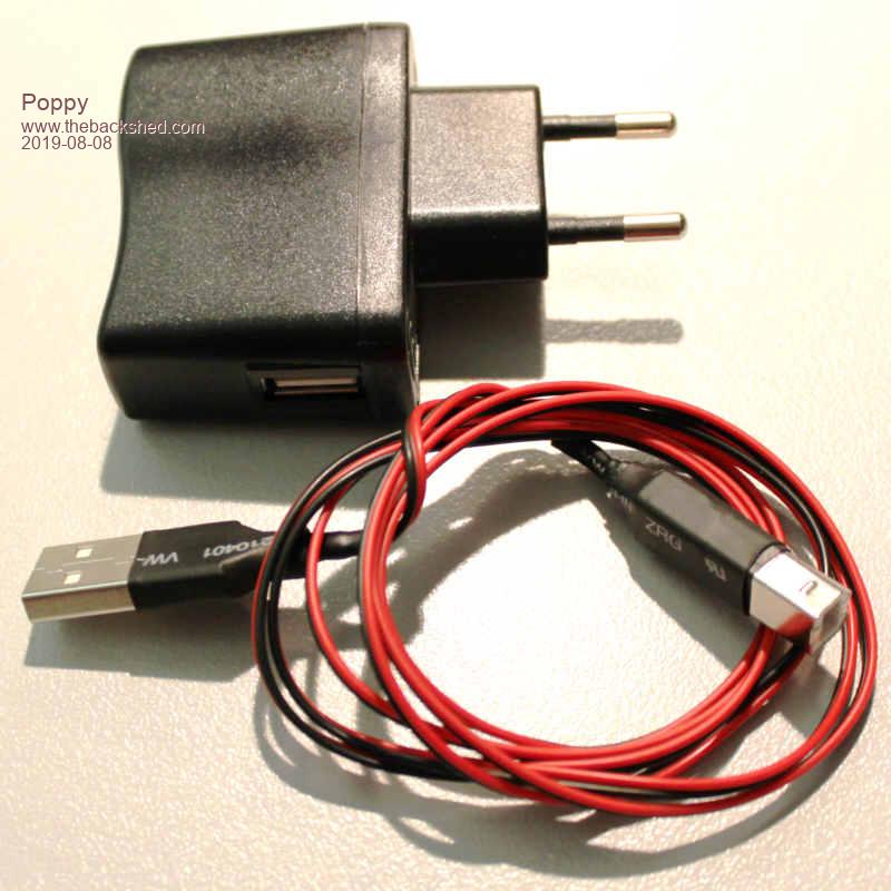 Andre ... such a GURU? Andre ... such a GURU? | ||||
Grogster Admin Group Joined: 31/12/2012 Location: New ZealandPosts: 9975 |
Hallo Poppy. D1 prevents damage to the board due to reverse-polarity applied to the DC socket, D2 and D3 form a simple diode OR gate, so that in the event of being powered by external DC, D2 will pass the power, and D3 will block it. When powered by USB, D3 will pass the power and D2 will block it. The idea is to prevent the external DC being fed back into the USB port 5v rail when powered externally, and to prevent the USB 5v from being fed back into the OUTPUT of the voltage regulator(not good!) if you are using USB power. Smoke makes things work. When the smoke gets out, it stops! |
||||
| The Back Shed's forum code is written, and hosted, in Australia. | © JAQ Software 2026 |
