
|
|
Forum Index : Microcontroller and PC projects : SD-Card, help me get this to work! (UBW32)
| Page 1 of 2 |
|||||
| Author | Message | ||||
| Decoy Senior Member Joined: 02/08/2019 Location: DenmarkPosts: 109 |
Hi guys I have ordered several SD-card readers, but this one (picture) arrived first. I have tried connecting it, but I cannot get it to work. Any advice on how to connect the leads between it and the UBW32? As a side question, what command would I use to get a list of the content on a SD card? Thanks! 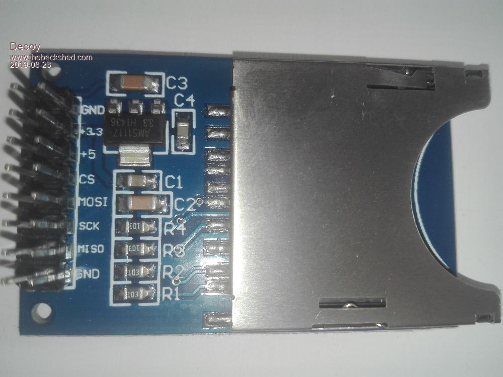 |
||||
| ceptimus Senior Member Joined: 05/07/2019 Location: United KingdomPosts: 130 |
Try GND - GND +3.3 - 3.3V +5 - don't connect CS - A1 MOSI - F4 SCK - F13 MISO - F4 GND - GND You probably need a link from the UBW32 GND to its D5 pin so it thinks the SD card is present - I can't see the pins for the card present switch on that adapter. You can use the Files command to list the SD card contents: just type files <enter> at the command prompt. Then to change directory (folder) - say to a folder called 'name' you use Chdir name To go 'back up' a level you use Chdir .. Edited 2019-08-23 05:51 by ceptimus |
||||
| Decoy Senior Member Joined: 02/08/2019 Location: DenmarkPosts: 109 |
ceptimus, thanks! I take it that MOSI -> F5 and MISO -> F4 Grounding pin D5 got me a little further - it now says "Error: Cannot access the SD card"  |
||||
| ceptimus Senior Member Joined: 05/07/2019 Location: United KingdomPosts: 130 |
yes sorry about typo. MOSI->F5 as you say. Ground pin D6 as well. |
||||
| Decoy Senior Member Joined: 02/08/2019 Location: DenmarkPosts: 109 |
Grounding D6 did not change the "Error: Cannot access the SD card" |
||||
| ceptimus Senior Member Joined: 05/07/2019 Location: United KingdomPosts: 130 |
I'm nervous suggesting this because I don't know about that particular card reader. You could try connecting the +5 to the UBW32's 5V.  But if the magic smoke escapes from your UBW32, it's not my fault!  Safer option would be to wait for a different card reader to arrive. |
||||
| Decoy Senior Member Joined: 02/08/2019 Location: DenmarkPosts: 109 |
Yeah, might be better to wait. I was wondering about the many resistors on this SD pcb. They don't seem to present on the other SD pcbs? Maybe I could solder directly to the pins on the sd card holder...but there seem to be 10 pins, not 9? I can feel that the SD card adventure will be an exercise in frustration  Thanks! |
||||
| ceptimus Senior Member Joined: 05/07/2019 Location: United KingdomPosts: 130 |
My home-made adapter that I photographed and put in an earlier thread also has the resistors. �They're just pull-up resistors to 3.3V about 20K I'll try linking to the image of the circuit here  [edit] cropped the image down to a reasonable size [/edit] Reading from left to right the connected pins on the SD card are chip (card) select data in ground 3.3V clock ground data out If you want to make a home-made micro SD card adapter, all you need is a spare micro-SD to SD adapter, and you can solder direct to the pads that normally contact inside a 'real' card reader. . . Edited 2019-08-23 07:21 by ceptimus |
||||
TassyJim Guru Joined: 07/08/2011 Location: AustraliaPosts: 6538 |
There were a lot of power related problems for some users. Some used a 3.3 ohm (?) resistor in the supply, others found a direct connection was better. I would use the 5V instead of 3.3V. That uses the on board regulator and should give a better regulation.I will check my wiring when I get back to the office but I am sure that I took the wiring straight from the CMM circuit diagram. Do you have a few different SD cards to test with? Jim VK7JH MMedit |
||||
| Decoy Senior Member Joined: 02/08/2019 Location: DenmarkPosts: 109 |
Thanks! I have other SD cards en route! :) |
||||
| TassyJim Guru Joined: 07/08/2011 Location: AustraliaPosts: 6538 |
OK I have had a chance to look at my UBW32 setup. I think it started out like your module and I cut the extraneous components off leaving a bare board. I like my bandsaw. The connections to the UBW32 are 75mm long. I have used 'complete modules on other boards without issue. I haven't added any pullups but they shouldn't be an issue. The 3.3V supply is directly connected to a fairly hefty regulator. Note the earthing link between the case and the pin 4th from the left. It connects to GND. I must have had a reason for doing that! Be warned - there could be holders with different pinouts, just to make life interesting. Jim VK7JH MMedit |
||||
| TassyJim Guru Joined: 07/08/2011 Location: AustraliaPosts: 6538 |
To add to the above: Jim VK7JH MMedit |
||||
| Decoy Senior Member Joined: 02/08/2019 Location: DenmarkPosts: 109 |
Hi Jim Thanks for your picture and the guide. However, it doesn't work. I have tried two different SD cards, and the 3.3 ohm resistor. No dice. I feel uncertain about my future with the MaxiMite - it seems very difficult to get this to work, and being a feature of paramount importance, I have to figure it out - or not use the system. Hold this against other hobbies, work, kids, painting fence etc. I am not sure if I can sink three weeks into getting the SD-card to work  Thanks! |
||||
| Poppy Guru Joined: 25/07/2019 Location: GermanyPosts: 486 |
Hi Decoy, could you show some explicit pictures how you�ve exactly done it, sometimes troubles are easier to spot that way. Andre ... such a GURU? | ||||
| ceptimus Senior Member Joined: 05/07/2019 Location: United KingdomPosts: 130 |
Are you still on the same SD card adapter? I think the problem is with that. It will probably work fine but only when its 5V pin is connected to 5V - and without more information that it's safe, I'd be reluctant to connect it to a 3.3V PIC chip (UBW32). If you wait for one of your other SD card interfaces to arrive, you'll probably find it works then - I doubt the problem is with the actual SD cards you're trying. I've found my Maximites work with all the cards I've tried - even old, low capacity cards that my PC won't recognize. Hopefully your other card readers will also have the little switches that detect when a card is present and if its 'read only' selector has been moved - then you can wire those to D5 and D6 instead of just grounding them. |
||||
| Decoy Senior Member Joined: 02/08/2019 Location: DenmarkPosts: 109 |
Okay! Thanks for not taking my quitter-attitude too seriously. I will wait for the standard red Sparkfun-ish version and try again. Thanks! |
||||
| Decoy Senior Member Joined: 02/08/2019 Location: DenmarkPosts: 109 |
By the way, I hope I am doing it right. When I boot the UBW32, and it enters MMBasic, it just presents the ">". This is where I enter "files" and then it returns "Cannot access SD card" This is correct, yes? |
||||
| ceptimus Senior Member Joined: 05/07/2019 Location: United KingdomPosts: 130 |
Yes that's right. After boot it defaults to the B: drive, which is the SD card. If you want to try it, enter the command drive A: ...which swaps to the PIC32's internal flash drive then you can do the files command to see how it works. you can load, save, chain, etc. files from drive A: just the same as drive B: the main difference is that the built-in drive A: only has a capacity of about 163k. |
||||
| Decoy Senior Member Joined: 02/08/2019 Location: DenmarkPosts: 109 |
Still waiting for other SD-card holder, but here is a picture of my former attempt, made with help from Jim and requested by Poppy :) This is connected to the UBW32 pins that Jim suggested, no dice. 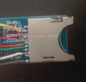 |
||||
| ceptimus Senior Member Joined: 05/07/2019 Location: United KingdomPosts: 130 |
Have you got anything connected to D5 and D6 with that device? If you have, you should see those pins floating high (about 3.3.V) when no SD card is inserted, and they should be pulled low (close to 0V) when you insert a normal SD card (one where you've not slid the little 'write protect' switch to the protect position). You can also disconnect any wires to D5/D6 and just link those two pins to GND - that way the Maximite always thinks a write-enabled card is inserted, even when it isn't. Another reason that board might not be working is that even though you've wired direct to the SD card pins, the other components on the board are still connected - so the pull-up resistors will be kind-of linking the SD pins together rather than pulling them up - because there isn't any 3.3V on the common side of the resistors. If the D5/D6 thing is already correct, I would next try leaving your card as-is but additionally connect 3.3V to the board pin marked 3.3 . Edited 2019-08-28 04:32 by ceptimus |
||||
| Page 1 of 2 |
|||||
| The Back Shed's forum code is written, and hosted, in Australia. | © JAQ Software 2026 |
