
|
|
Forum Index : Microcontroller and PC projects : Extreme64 and PS2 kb & Mouse
| Author | Message | ||||
bigmik Guru Joined: 20/06/2011 Location: AustraliaPosts: 2981 |
Hi All, I am playing around with a layout for an Extreme64 based PCB. (very early stages) As usual I am trying to keep this board as small as possible.. Due to the fact the VGA is not available on the X64 is there a need for the Mouse and keyboard PS2 connectors? These are relatively bulky and it would be nice to not have them on the board.. I am after opinions as whether these are really useful on the X64 or not.. I can utilise the space for other items Anyway I am interested in your opinions. Kind Regards, Mick Mick's uMite Stuff can be found >>> HERE (Kindly hosted by Dontronics) <<< |
||||
| CaptainBoing Guru Joined: 07/09/2016 Location: United KingdomPosts: 2171 |
Personally I like the PS2 keyboard option, but that is just me. Try to find space for a Winbond Flash memory . I know the MMX can't do CSubs but you can drive the flash rams from MMBasic quite easily. The speed of the X will make it realistic enough I think, no? Edited 2019-09-07 00:04 by CaptainBoing |
||||
| bigmik Guru Joined: 20/06/2011 Location: AustraliaPosts: 2981 |
Hi Capn, Thanks for the reply,, Nice little chip and cheap (W25Q64FVSSIG) at about $1 each.. But I need to know for sure that one of these can be used on the X64 driven from basic otherwise it becomes a waste of space. We all know my ability (or lack there of) to program so I doubt I could write code to test it. Re. The PS2, I am exploring a couple of other options (Piggy back plug in PCB) or header pins and a converter cable (prob using one of those 2 PS2 to USB cables and modifying it) as I am trying to squeeze everything onto a 50mm square PCB.. So far it is looking ok but those damn PS2 connectors are taking a lot of room. Kind Regards, Mick Mick's uMite Stuff can be found >>> HERE (Kindly hosted by Dontronics) <<< |
||||
| CaptainBoing Guru Joined: 07/09/2016 Location: United KingdomPosts: 2171 |
agree with that.... PS2 blocks take a lot out of 50mm sq . With the flash RAM chip; Pete M mentions, in that article I linked, "it was all written first in Basic and then just converted to C for improved performance". Looking at the data sheet there is nothing exotic about controlling it (bit fiddly in places e.g. with the pages etc.) but maybe if he is willing to release that code it might go some way to addressing your (valid) concerns. I prefer a pure MMBasic solution just to provide cross-platform compatibility... it also helps in that I don't do C and so writing CSubs are beyond my skills... �  It doesn't matter anyway - whichever pin you designate as CS for it will get in the way of someones work �  It was just a thought. My Mk5 mini controller board has space for one - I had the room and thought it was a nice touch - just in case. 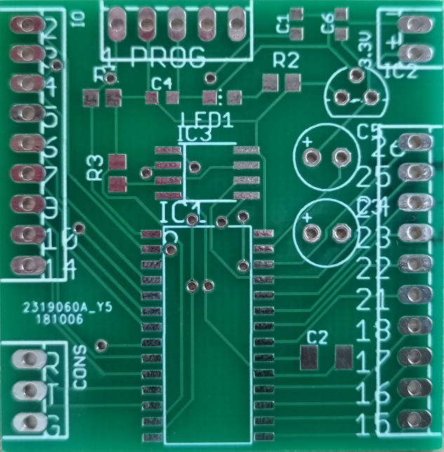 This little board is a real workhorse - I use them everywhere - dead easy to build up and just gets on with business no problems. The use of a 78L33 won't be to everyone's tastes it is easy to "jumper" when provided with 3.3v on the input and can work all the way up to 12v with a single solution and no hassles, plus I got stacks of them left over have fun Edited 2019-09-07 18:44 by CaptainBoing |
||||
| PeterB Guru Joined: 05/02/2015 Location: AustraliaPosts: 669 |
Good morning Mick If you use a header it becomes just another useful connector that can be used for whatever. It should be possible/easy to make up a free PS2 to header cable. Are there other pins available that can be connected to the same header? Peter p.s. I like CB's board but there are no bolt holes  P |
||||
OA47 Guru Joined: 11/04/2012 Location: AustraliaPosts: 1050 |
Mik, what about just supplying a header for PS2 connectors so that if they are needed a simple cable can be made. OA47 EDIT: PeterB replied at the same time. Edited 2019-09-08 09:36 by OA47 |
||||
| PeterB Guru Joined: 05/02/2015 Location: AustraliaPosts: 669 |
OA47 SNAP Peter |
||||
| bigmik Guru Joined: 20/06/2011 Location: AustraliaPosts: 2981 |
Hi All, Thank you for your input. I most likely will scrap the PS2 connectors as they take up so much room, and use a header to gain connectivity if required, I might make a small daughter PCB that has the Audio jack and kb/mouse on it.. I have ordered one of these to strip down. 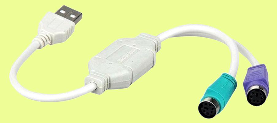 It would be easy enough to use the cables and terminate them at a header to match the main board.. As to the flash memory, I have bought 10 to play with (A massive 55c AU each for the W25Q64FVSSIG). I have had a quick scan of the data sheet and I am a little concerned about the following specs. 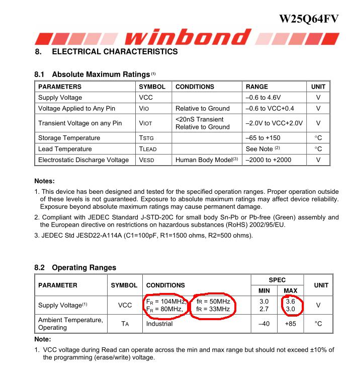 I am yet to determine what Fr really means but if operating at 80MHz/33Mhz the max Vcc seems to be 3.0v Hmmm... I am sure they work well but just a thing to ponder Kind Regards, Mick Edited 2019-09-08 12:18 by bigmik Mick's uMite Stuff can be found >>> HERE (Kindly hosted by Dontronics) <<< |
||||
| CaptainBoing Guru Joined: 07/09/2016 Location: United KingdomPosts: 2171 |
'tis true. This board has influenced my enclosure design and is held by either plastic clips as part of the case or a double-sided sticky foam pad (this is surprisingly good). Other versions do have holes, but this is the only one with the Winbond Flash RAM position. I must confess to ignorance about that but I haven't had any problems at a stock 3v3. Maybe I have been lucky? Edited 2019-09-09 07:41 by CaptainBoing |
||||
| ceptimus Senior Member Joined: 05/07/2019 Location: United KingdomPosts: 130 |
I read that spec. as saying you can run at the higher frequency with the higher voltage supply. This is quite normal. So you can run at a maximum of 80/33 (I guess they are the figures for the two directions?) with a 3-volt supply, and the speed limit increases to 104/50 when you have a 3.3-volt supply. |
||||
| bigmik Guru Joined: 20/06/2011 Location: AustraliaPosts: 2981 |
Hi Ceptimus, It possibly does mean that but I feel that it looks like it is in reverse.. It states the Fr as (CONDITIONS) so I read the Vcc being max 3.0v Very confusing.. but some people apparently have this working OK.. What sort of Fr would an X64 at 200/252 MHz create? On the same agenda should I look at the 2 bit or 4 bit SPI options? that would take either 1 or 3 EXTRA IO pins? I would provide a pad for access if required. Interesting... My MZ chip and 24Hz Xtal arrived today so I am just waiting for my TQFP-header pins adapter to breadboard a bit of the circuit. I was also a bit surprised at the price of the MZ chip ($22AU from RS Components and not much less from Mchip) Regards, Mick Mick's uMite Stuff can be found >>> HERE (Kindly hosted by Dontronics) <<< |
||||
| BrianP Senior Member Joined: 30/03/2017 Location: AustraliaPosts: 292 |
That 24Hz xtal must be a pretty big rock...  |
||||
| bigmik Guru Joined: 20/06/2011 Location: AustraliaPosts: 2981 |
@Brian, Actually, (Yes I know you were joking), I almost couldn't find it in its plastic bag.. It is a whopping �3.2mm x 2.5mm and was darn hard to solder some wires on to test it �in my X144 board. (yes it works fine even without the pin 1 mod). This might be a challenge for someone to solder but then the 0.5mm pitch on the MZ is not going to be for home handyman solderers either. Flux will be a must. Here is a rough as guts picture next to a 0.1" shorting link 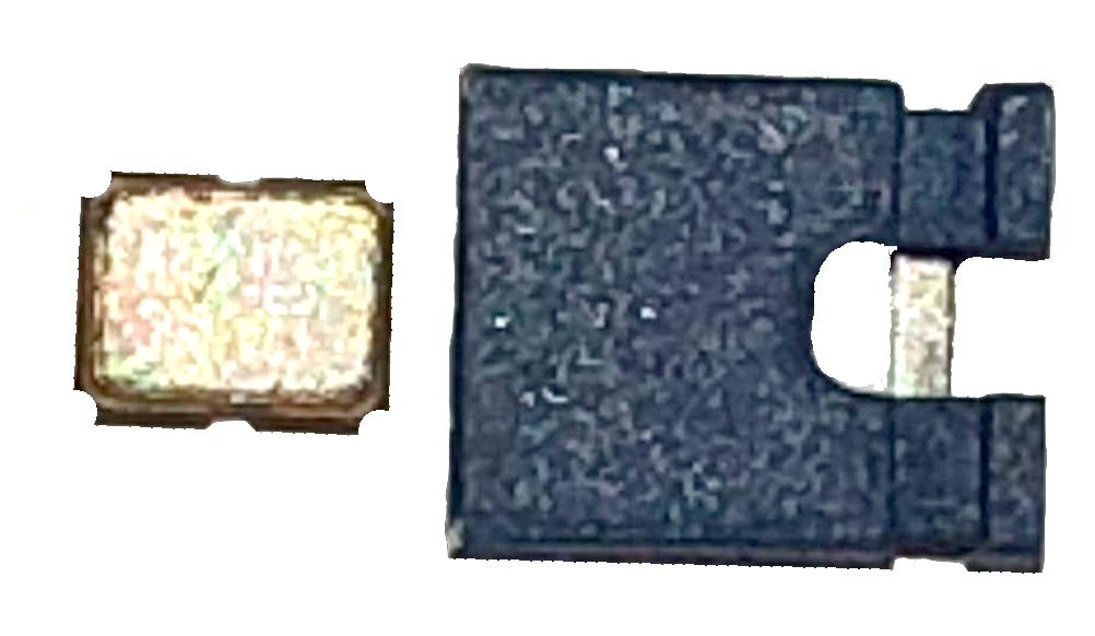 Kind Regards, Mick EDIT !!! Wow! Look at the size the image came out as.. Edited 2019-09-09 12:16 by bigmik Mick's uMite Stuff can be found >>> HERE (Kindly hosted by Dontronics) <<< |
||||
TassyJim Guru Joined: 07/08/2011 Location: AustraliaPosts: 6538 |
I have been playing with the W25Q16JV which comes on the STM32F4 board. The data sheet is similar to the W25Q64FV. This is the circuit for the flash chip: 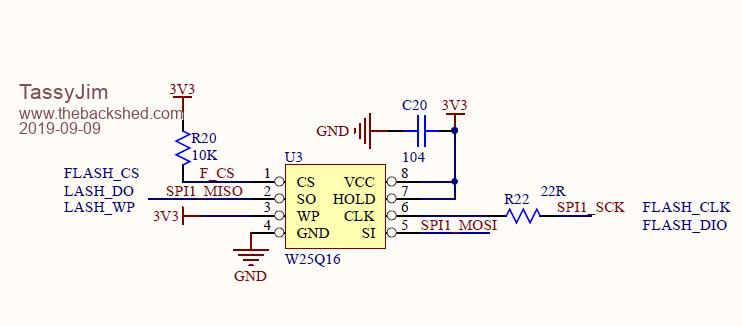 Note the 3.3Vsupply and also the WP and HOLD pins tied to 3.3V The chips supplied on my boards are of the variety that default to QUAD ENABLE being set! 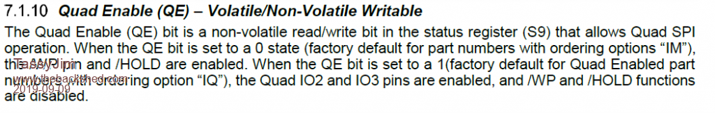 The speed I am using to talk to the chips is: SPI OPEN 1000000,0,8 I haven't done anything more than read the serial number and status registers etc but will try saving and retrieving data next. As it is not a MX chip, I can't use Peters CFunctions but the exercise has been good for the grey matter. > RUN Device ID = EF14 JEDEC ID = EF4015 Serial No = E66840D843431B36 Status registers: 1 00000000 2 00000010 3 01100000 1 00000010 2 00000010 3 01100000 > I think you will be safe with 3.3V Jim VK7JH MMedit |
||||
Chopperp Guru Joined: 03/01/2018 Location: AustraliaPosts: 1126 |
Thanks Jim. That worked on one of my F4's. I can understand a bit of it. Not used SPI this way before. Looking forward to updates. Brian ChopperP |
||||
| The Back Shed's forum code is written, and hosted, in Australia. | © JAQ Software 2026 |
