
|
|
Forum Index : Microcontroller and PC projects : Huntron tracker on LCD backpack
| Author | Message | ||||
| TrevorH Senior Member Joined: 06/04/2018 Location: United KingdomPosts: 142 |
@Volhout On the schematic R9 is shown as value 1E, what value should it be? Trevor |
||||
| Volhout Guru Joined: 05/03/2018 Location: NetherlandsPosts: 3513 |
Hi TrevoH, 1E means 1 ohm Regards, Volhout PicomiteVGA PETSCII ROBOTS |
||||
| TrevorH Senior Member Joined: 06/04/2018 Location: United KingdomPosts: 142 |
Hi, Thanks for that, never seen that before, you learn something every day.  Trevor. |
||||
| Pluto Guru Joined: 09/06/2017 Location: FinlandPosts: 329 |
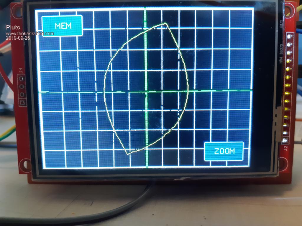
Thank you Volhout for the interesting project!  I had not heard about the Huntron Tracer before, but vhen I saw your project I got immediately interested and started to build the circuit on some stripboads. After some error corrections (my errors/not yours) I got it to function as expected. Some googling confirmed that the traces are as to be expected for various components. I am using a 28pin MX170 with ILI9341 display. Did not have MC34063 so it was replaced by MC33063. likevise LM741 was replaced by UA741. All powerd from a CP2102 USB to TTL module. I think it could be useful to have some kind of gridlines or grid dots and scales for x and y axis, e.g. for testing zener diodes. High accuracy for voltage and current would NOT be required. If part of the gridlines would be "erased" by the measurement traces, that would not be a problem (restart with refreshed gridlines is very fast). How difficult would it be to add gridlines and scales based on the information collected in the calibrations? R16 is 3.9k (according to your correction earlier). R16 is the output resistance of the instrument. If a lower output resistance is required, is it simply to replace 3.9k by e.g. 1k? Suppose that R15 (47k) then also need to be changed?  |
||||
| BrianP Senior Member Joined: 30/03/2017 Location: AustraliaPosts: 292 |
FWIW I thought it was the R operator for values less than 1k, as in 560R etc. 1.5 ohm would be 1R5. After 1k we go to 5k6 for 5.6k, 560k 5m6 for 5.6 meg & so on. Then again, I may be wrong...  B |
||||
| Volhout Guru Joined: 05/03/2018 Location: NetherlandsPosts: 3513 |
Hi Pluto, Your suggestion to lower the output impedance to 1k may work. I would change the 47k resistor to 51k to prevent overdriving the ADC (clipping). There may be some effect for the power supply and opamp though. The opamp output is +/- 14V roughly. With 1k output resistance that would be 14mA in case of a short circuit. I have not checked if the power supply can deliver this much power at +/- 16V. You may need bigger caps and diodes. And maybe need to change the 1 ohm to 0.5 ohm. The MC33063 is fine. It has different temperature range, but for the rest is seems identical. I am glad you are having fun with the circuit.... Volhout P.S. the grid could be a solution, I'll look into it. Alternatives could be that when touching the area you are interested in on the LCD, it shows voltage an current in the display. Alternatively...more difficult...I could "seach for the "knee" and show voltage an current at the knee, and at both extremes. A knee could be defined as where the trace makes a 45 degree angle with axes. Edited 2019-09-26 23:17 by Volhout PicomiteVGA PETSCII ROBOTS |
||||
| Pluto Guru Joined: 09/06/2017 Location: FinlandPosts: 329 |
 Horisontal grid approximately 2V per division and vertical about 1mA per div. in normal mode. About 1V/div in ZOOM mode (No decimals!) This is in fact sufficient accuracy for me to get approximate zener voltages, LED voltages, etc. Added just a few lines to Volhout's code in Sub draw_window : 'draw grids line mm.hres*0.113,1,mm.hres*0.113,mm.vres line mm.hres*0.1904,1,mm.hres*0.1904,mm.vres line mm.hres*0.2678,1,mm.hres*0.2678,mm.vres line mm.hres*0.3452,1,mm.hres*0.3452,mm.vres line mm.hres*0.4226,1,mm.hres*0.4226,mm.vres line mm.hres*0.5,1,mm.hres*0.5,mm.vres,3,rgb(green) line mm.hres*0.5774,1,mm.hres*0.5774,mm.vres line mm.hres*0.6548,1,mm.hres*0.6548,mm.vres line mm.hres*0.7322,1,mm.hres*0.7322,mm.vres line mm.hres*0.8096,1,mm.hres*0.8096,mm.vres line mm.hres*0.887,1,mm.hres*0.887,mm.vres line 1,mm.vres*1/8,mm.hres,mm.vres*1/8 line 1,mm.vres*2/8,mm.hres,mm.vres*2/8 line 1,mm.vres*3/8,mm.hres,mm.vres*3/8 line 1,mm.vres*4/8,mm.hres,mm.vres*4/8,3,rgb(green) line 1,mm.vres*5/8,mm.hres,mm.vres*5/8 line 1,mm.vres*6/8,mm.hres,mm.vres*6/8 line 1,mm.vres*7/8,mm.hres,mm.vres*7/8 I am sure there are more clever ways to do it than my quick and dirty approach. Please note that the grids are gradually disappearing when curves are displayed over the grids. Fresh grids by restarting the program. Thanks Volhout for an interesting instrument. Looking forward to see coming versions! Fred (Pluto) |
||||
| Volhout Guru Joined: 05/03/2018 Location: NetherlandsPosts: 3513 |
Hi Pluto, About the degradation of the grid lines. If you add these lines to the touch interrupt (just before the end), then at every touch at the LCD the grid is redrawn. That is what I plan to do, regardless whatever method or alternative I choose... Volhout PicomiteVGA PETSCII ROBOTS |
||||
| TrevorH Senior Member Joined: 06/04/2018 Location: United KingdomPosts: 142 |
@BrianP, Your right about the standard notation of resistor values, thanks for sharing, however never seen such as 1E before, wonder if this is a thing used in the Netherlands  Volhout??? PS I am having a go at making it work on MM+ and 5inch SSD1963 centering plots on screen is an interesting problem. Trevor |
||||
| Volhout Guru Joined: 05/03/2018 Location: NetherlandsPosts: 3513 |
Hi Pluto, TrevorH, First of all, the 1E is something I don't know where I got this from. May have been a habit from one of my former jobs? I planned this week to work on the board layout, but was triggered by the work done by Pluto to improve the software. So I spend some time behind the screen, and added dynamic measurements. Found that more accurate than a grid. The measurement values are calculated from screen coordinates, and are therefore not as accurate as the ADC could do, but since we do relative measurements mainly, this seems accurate enough. Actually, it is so accurate that we may not need the zoom mode anymore.... Here a screen shot 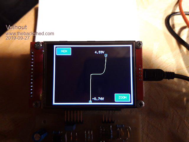 I am a bit hesitant to insert the code, since it is becoming large. But anyway, here is the listing. The measurements are calculated using is 1 second timer, so it doe not slow down the waveform plotting constantly. Enjoy.... '+-------------------------------------------------------------+ '| | '| BACKPACK TRACKER | '| | '| 09-2019 Volhout @ TheBackShed.com | '+-------------------------------------------------------------+ ' Curve tracer type huntron tracker ' For ILI9341 LCD backpack on 28 pin MX170 ' Uses pin 24 as analog input ' Uses pin 4 as pwm output ' Uses pin 9 and 10 to set amplifier gain ' all values scaled to 'resolution' ' there are 'samples' measurements per period '------------------------- Version History ------------------ ' V00 Proof of concept with 640 samples 100 resolution ' V01 Increase resolution to 1000, decrease samples to 200 ' V02 Implemented touch for REF and ZOOM buttons, REF added ' V03 Optimized main loop from 400msec to 300msec ' V04 Implemented support for HW zoom ' V05 Zoom implemented in SW ' V06 Restructure code to support samples and resolution as constants ' V07 Tune performance on MX170 ( 8 frames / second ) ' V08 Improved code for readability, remove obsolete DIM's ' V09 Screen resolution independent (untested), added header ' V10 Add dynamic measurement values '------------------------------ init ------------------------ Option explicit init: 'PIC32MX170 initialisation CPU 48 ' max speed SetPin 24,ain ' voltage input PWM 1,120000,50 ' set PWM to 0Vdc amp_high_gain ' set amplifier gain ' Define samples each scan Const samples = 64 Const resolution = 1000 ' external ADC divider (R15=47k into R10=12k//R11=15k) Const R10_R11 = 12000*15000/(12000+15000) Const resistor_divider = (47000 + R10_R11)/R10_R11 ' Declare variables ------------------------------------------------- ' Declare defaults for scaling ADC to 'resolution', these values ' are fine tuned in calibration (at powerup) Dim integer lowgain=resolution/3.3, highgain=2*lowgain Dim gain=lowgain Dim integer lowoffset=0, highoffset=-resolution/2 Dim offset=lowoffset ' for user interface, xt/yt are touch coordinates Dim integer xt,yt ' generic i,j,h are counters, ADC is scaled adc value, adc10 and adc90 ' are used in calibration Dim integer i,j,h,ADC Dim float adc10,adc90 ' display waveform, x/y are measured waveform, xr/yr are memory reference Dim integer x0,y0,x(samples),y(samples),xr(samples),yr(samples) ' init coordinates with values that fit the screen For i=1 To samples xr(i)=MM.HRes-3:yr(i)=MM.VRes/2:x(i)=MM.HRes-3:y(i)=MM.VRes/2 Next i x0=MM.HRes-3:y0=MM.VRes/2 ' display numerics, xnl/ynl for left side, xnr/ynr for right side Dim integer xnr=100,xnl=100,ynr=100,ynl=100,yor=0,yol=0 Dim float vr,ir,vl,il ' generate waveform, pw = pwm value, pc = pwm value scaled to 'resolution' Dim pw(samples), pc(samples) ' fill waveform with triange wave 0...100% For i=1 To samples / 2 pw(i) = 100 - ( 200 / samples ) * i pc(i) = resolution * pw(i) / 100 pw(i + samples / 2) = ( 200 / samples ) * i pc(i + samples / 2) = resolution * pw(i + samples / 2) / 100 Next ' graphics scaling to resolution Dim float Vstep = MM.VRes / resolution, Hstep = MM.HRes / resolution Dim center = resolution / 2 ' buttons and line colors Dim integer membuttoncolor = RGB(blue), zoombuttoncolor = RGB(blue) Dim integer memcolor = RGB(black), linecolor = RGB(yellow) 'debug 'Memory ' initialize screen draw_window ' enable touch SetPin 15, INTL, Touch_Int ' timed interrupts SetTick 1000, Time_Int, 1 ' calibrate analog circuits calibrate '------------------------------ MAIN ------------------------ main: ' all comments removed from main loop to speed it up ' cycle through all pwm values using pointers i (actual) and j (last) ' erase last segment ' allways draw memory line, but color decides if it is visible ' draw memory line first so actual overwrites memory ' measure input value ' recalculate new segment (huntron method) ' draw new segement Do 'Timer = 0 For i = 1 To samples j = i - 1 : If j = 0 Then j = samples PWM 1,120000,pw(i) Line x0,y0,x(i),y(i),1,0 Line xr(j),yr(j),xr(i),yr(i),1,memcolor x0 = x(i) : y0 = y(i) ADC=(Pin(24) * gain) + offset y(i)=(ADC - pc(i) + center) * Vstep x(i)= ADC * Hstep Line x(j),y(j),x(i),y(i),1,linecolor Next i 'Print Timer Loop '--------------------------- SUBS --------------------------- Sub Touch_Int xt = Touch(x) : yt = Touch(y) 'check for MEM button if we should display memory If xt < ( MM.HRes / 4 ) And yt < ( MM.VRes / 4 ) Then If memcolor = RGB(black) Then For h = 1 To samples 'copy live to REF line yr(h) = y(h) xr(h) = x(h) Next memcolor = RGB(red) membuttoncolor = RGB(red) Else memcolor = RGB(black) membuttoncolor = RGB(Blue) End If RBox 10,10,60,30,2,RGB(white),membuttoncolor Text 30,18,"MEM",,,,RGB(white),membuttoncolor End If 'check for ZOOM button to see if we should zoom in If xt > (3 * MM.HRes / 4 ) And yt > (3 * MM.VRes / 4) Then If zoombuttoncolor = RGB(blue) Then zoombuttoncolor = RGB(red) adc_high_gain amp_low_gain Else zoombuttoncolor = RGB(Blue) adc_low_gain amp_high_gain End If RBox MM.HRes-70,MM.VRes-40,60,30,2,RGB(white),zoombuttoncolor Text MM.HRes-55,MM.VRes-32,"ZOOM",,,,RGB(white),zoombuttoncolor End If draw_frame Pause 300 'prevent double touch End Sub Sub amp_high_gain SetPin 9,dout : Pin(9)=0 SetPin 10,dout : Pin(10)=1 End Sub Sub amp_low_gain SetPin 9,din SetPin 10,din End Sub Sub adc_high_gain gain = highgain offset = highoffset End Sub Sub adc_low_gain gain = lowgain offset = lowoffset End Sub Sub draw_window 'clear screen CLS 'draw outside lines draw_frame 'draw buttons RBox 10,10,60,30,2,RGB(white),membuttoncolor Text 30,18,"MEM",,,,RGB(white),membuttoncolor RBox MM.HRes-70,MM.VRes-40,60,30,2,RGB(white),zoombuttoncolor Text MM.HRes-55,MM.VRes-32,"ZOOM",,,,RGB(white),zoombuttoncolor End Sub Sub calibrate 'calibrate standard mode ------------ amp_high_gain adc_low_gain 'measure 10% and 90% points PWM 1,120000,10 Pause 1 adc10 = Pin(24) PWM 1,120000,90 Pause 1 adc90 = Pin(24) 'calculate ADC low gain and offset lowgain = 80 * resolution / (100 * (adc90 - adc10)) lowoffset = - lowgain * (adc10 - ((adc90 - adc10)/8)) 'Print lowgain , lowoffset 'calibrate zoom mode -------------- amp_low_gain adc_high_gain 'measure 10% and 90% values PWM 1,120000,10 Pause 1 adc10 = Pin(24) PWM 1,120000,90 Pause 1 adc90 = Pin(24) 'calculate ADC high gain and offset highgain = 80 * resolution / (100 * (adc90 - adc10)) highoffset = - highgain * (adc10 - ((adc90 - adc10)/8)) 'Print highgain , highoffset 'back to standard mode amp_high_gain adc_low_gain End Sub Sub draw_frame 'draw outside lines Line 1,1,1,MM.VRes-3,3,RGB(white) Line 1,MM.VRes-3,MM.HRes-3,MM.VRes-3,3,RGB(white) Line MM.HRes-3,MM.VRes-3,MM.HRes-3,1,3,RGB(white) Line MM.HRes-3,1,1,1,3,RGB(white) End Sub Sub Time_Int Print x(1),y(1),x(1+samples/2), y(1+samples/2) 'erase old text Text xnr-7,ynr+yor," ",r,,,0,0 Text xnl+7,ynl+yol," ",l,,,0,0 'write markers Box xnr-5,ynr-5,9,9,,0 Box xnl-5,ynl-5,9,9,,0 ' calculate voltage xnr = x(samples): ynr = y(samples): xnl = x(samples/2): ynl = y(samples/2) vr = resistor_divider * (((xnr - MM.HRes / 2) / Hstep)) / gain vl = resistor_divider * (((xnl - MM.HRes / 2) / Hstep)) / gain ' repair corrupted frame draw_frame 'write markers Box xnr-5,ynr-5,9,9,,RGB(cyan) Box xnl-5,ynl-5,9,9,,RGB(cyan) 'get new coordinates for writing text, and write If ynr < 30 Then yor=5 Else yor=-20 If ynl > MM.VRes-30 Then yol=-20 Else yol=5 Text xnr-7,ynr+yor,Str$(vr,0,2)+"V",r,,,RGB(white),0 Text xnl+7,ynl+yol,Str$(vl,0,2)+"V",l,,,RGB(white),0 End Sub PicomiteVGA PETSCII ROBOTS |
||||
| CaptainBoing Guru Joined: 07/09/2016 Location: United KingdomPosts: 1985 |
Hi Volhout. I don't think it's a problem (Glenn?) but you are more than welcome to create a wiki here if you are worried about it. There are already several entire projects here complete with schematics, discussion, large amounts of code and even some PC-based support code where necessary. cheers h Edited 2019-09-27 17:29 by CaptainBoing |
||||
| Volhout Guru Joined: 05/03/2018 Location: NetherlandsPosts: 3513 |
Small project hardware update. I noticed that the opamp LM741 runs close to saturation when driving -14V. The LM741 was chosen because it has a max voltage rating of +/-22V. In our circuit t is powered from +16.2V/-15.3V which is safe. Can't use a +/-15V rated opamp though. So I decided to increase the voltage from the power supply to +16.8V, and the negative voltage to -16.5V. This is done by following changes: R17 changes to 15k R13 changes to 1.2k Diodes D1 and D3 change to small schottky diodes (BAT85 or 1N5819). I will reflect these changes in an updated schematic later this week. Another thing: I noticed that the LM741 and uA741 parts are basically obsolete. Prices at Farnell are up to 10 euro per piece. A good replacement would be the MC34071 or the TLE2141. These are available in DIL and have +/- 22V supply range (cost around a dollar). Haven't tested these part yet. If there is demand for this circuit beyond the 3 or 4 people involved now, I may redesign it to work with standard +/-15V opamps or use a discrete amplifier. That's all folks.... Edited 2019-09-27 18:23 by Volhout PicomiteVGA PETSCII ROBOTS |
||||
| CaptainBoing Guru Joined: 07/09/2016 Location: United KingdomPosts: 1985 |
On price alone, I think we are a long way off having to worry. Edited 2019-09-27 19:12 by CaptainBoing |
||||
| Pluto Guru Joined: 09/06/2017 Location: FinlandPosts: 329 |
Hi Volhout, I replaced the UA741 op-amp with TLE2141IP (+/-22V max supply). Voltage output swing improved from 25.7V to 26.5V and the shape of the output wawe improved at the minimum output voltage; Became a sharper "V" with TLE2141. TLE outputs are very equal for negative and positive outputs. Better than LM741. I do not have MC34071 for testing. The price of TLE2141 is $3.5/5pcs=$0.70/pcs from AliExpress. Same cost as MC34071. Tested your new program version. I like it! Thanks! |
||||
| Volhout Guru Joined: 05/03/2018 Location: NetherlandsPosts: 3513 |
Hi Pluto, Thanks for testing the TLE2141. I was a bit worried about that one because it has much higher bandwidth. I improved the program a bit more, it only draws the numeric values when they change. It is easier on the eyes, the erasing and drawing of the text was visible and annoying to me. The change is only in the time interrupt routine. I will only post that section here. Sub Time_Int 'check if left marker needs update If ynl <> y(samples/2) Then 'erase old text Text xnl+7,ynl+yol," ",l,,,0,0 'write markers Box xnl-5,ynl-5,10,10,,0 ' calculate voltage xnl = x(samples/2): ynl = y(samples/2) vl = resistor_divider * ((xnl - MM.HRes / 2) / Hstep) / gain ' repair corrupted frame draw_frame 'write markers Box xnl-5,ynl-5,10,10,,RGB(cyan) 'get new coordinates for writing text, and write If ynl > MM.VRes-30 Then yol=-20 Else yol=5 Text xnl+7,ynl+yol,Str$(vl,0,2)+"V",l,,,RGB(white),0 End If ' check if right marker needs an update If ynr <> y(samples) Then 'erase old text Text xnr-7,ynr+yor," ",r,,,0,0 'write markers Box xnr-5,ynr-5,10,10,,0 ' calculate voltage xnr = x(samples): ynr = y(samples) vr = resistor_divider * ((xnr - MM.HRes / 2) / Hstep) / gain ' repair corrupted frame draw_frame 'write markers Box xnr-5,ynr-5,10,10,,RGB(cyan) 'get new coordinates for writing text, and write If ynr < 30 Then yor=5 Else yor=-20 Text xnr-7,ynr+yor,Str$(vr,0,2)+"V",r,,,RGB(white),0 End If End Sub PicomiteVGA PETSCII ROBOTS |
||||
| zeitfest Guru Joined: 31/07/2019 Location: AustraliaPosts: 377 |
The original thread discussed a screen refresh rate issue, here Did the changed line update technique fix it ? |
||||
| Volhout Guru Joined: 05/03/2018 Location: NetherlandsPosts: 3513 |
Hi zeitfest, The original thread was the initial idea, where a voltage to voltage graph would be shown. While studying the idea, i realized a voltage to current graph would be needed. That threw overboard the initial plotting algorythm. Numberwise, we are plotting 3 times 64 segments, 8 times per second in this version. That is 1500 segments per second.(lines). The orinial thread did plot pixels, 640 of them 3 times per second, and erases as many, that is 3800 pixels per second. Resolution in this version is lower, but it has a lot more functionality. Actually, it is a working product in thi stage. Volhout Edited 2019-09-28 06:46 by Volhout PicomiteVGA PETSCII ROBOTS |
||||
| Volhout Guru Joined: 05/03/2018 Location: NetherlandsPosts: 3513 |
I updated the schematics, and show a layout proposal. 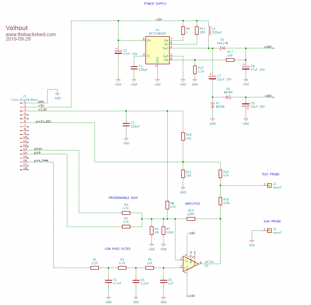 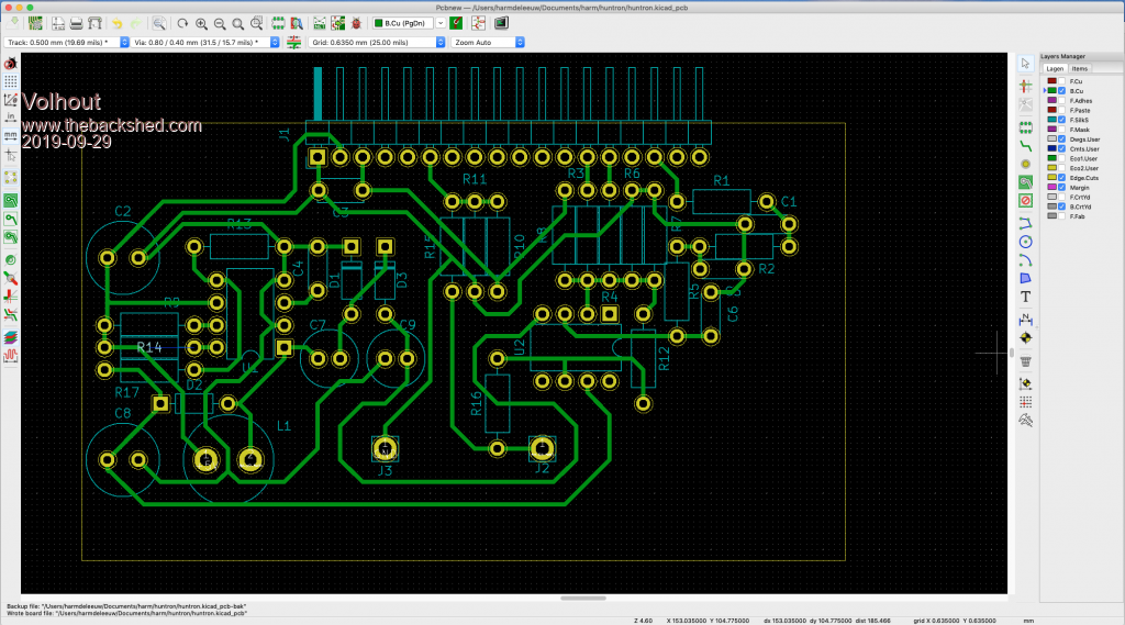 Happy prototyping Volhout Edited 2019-09-29 02:25 by Volhout PicomiteVGA PETSCII ROBOTS |
||||
| Volhout Guru Joined: 05/03/2018 Location: NetherlandsPosts: 3513 |
Software version V11 is available. This version works on the Micromite Backpack (MX170) and the ARMmiteF4 The ARMmiteF4 is double as fast. However, on my test where the hardware was wired through 25cm long wires, the ARMmiteF4 was more noisy. This may be caused by noise on the ground wire, showing as noise at the A/D converter input. I haven't checked the F4 in that detail. Things I must investigate yet: - does the PWM run at 120kHz (if not that will cause inaccuracy due to the filtering in the PWM filter) - are the PE2 and PE6 pins noise free (gain control) - is the LCD update so fast, and the ADC so fast, that the settling time in the hardware is insufficient (opamp speed, PWM filter). - check the ground noise at the ADC (as said above). Anyway, here is the code, universal for both backpacks. '+-------------------------------------------------------------+ '| | '| BACKPACK TRACKER | '| | '| 10-2019 Volhout @ TheBackShed.com | '+-------------------------------------------------------------+ ' Curve tracer type huntron tracker ' For ILI9341 LCD backpack on 28 pin MX170 ' Uses pin 24 as analog input ' Uses pin 4 as pwm output ' Uses pin 9 and 10 to set amplifier gain ' all values scaled to 'resolution' ' there are 'samples' measurements per period ' V11 has support for ARMmiteF4 '------------------------- Version History ------------------ ' V00 Proof of concept with 640 samples 100 resolution ' V01 Increase resolution to 1000, decrease samples to 200 ' V02 Implemented touch for REF and ZOOM buttons, REF added ' V03 Optimized main loop from 400msec to 300msec ' V04 Implemented support for HW zoom ' V05 Zoom implemented in SW ' V06 Restructure code to support samples and resolution as constants ' V07 Tune performance on MX170 ( 8 frames / second ) ' V08 Improved code for readability, remove obsolete DIM's ' V09 Screen resolution independent (untested), added header ' V10 Add dynamic measurement values ' V11 Support for ArmiteF4 (untested with hardware) '------------------------------ init ------------------------ Option explicit init: If MM.Device$ = "ARMmite F407" Then 'STM32F407VET6 initialisation 'OPTION LCDPANEL ILI9341_16, LANDSCAPE 'TOUCH PB12, PC5 Const ADC_PIN = 15 ' 15/PC0 for F4 Const HI_GAIN_HI = 1 ' switch to high gain, PE2/pin1 for F4 Const HI_GAIN_LO = 5 ' switch to high gain, PE6/pin5 for F4 GUI interrupt Touch_Int Else 'PIC32MX170 initialisation 'OPTION LCDPANEL ILI9341, L, 2, 23, 6 'OPTION TOUCH 7, 15 CPU 48 ' max speed - not needed in ARM F4 Const ADC_PIN = 24 ' 24 for MX170 Const HI_GAIN_HI = 10 ' switch to high gain, 10 for MX Const HI_GAIN_LO = 9 ' switch to high gain, 9 for MX ' enable touch SetPin 15, INTL, Touch_Int End If 'start board SetPin ADC_PIN,ain ' voltage input ADC1-ch10 (at pin 15) PWM 1,120000,50 ' set PWM to 50% (0Vdc amplifier out) ' pin 31/PA6 on F4, pin 4 on MX170 amp_high_gain ' set amplifier gain ' Define samples each scan Const samples = 64 Const resolution = 1000 ' external ADC divider (R15=47k into R10=12k//R11=15k) Const R10_R11 = 12000*15000/(12000+15000) Const resistor_divider = (47000 + R10_R11)/R10_R11 ' Declare variables ------------------------------------------------- ' Declare defaults for scaling ADC to 'resolution', these values ' are fine tuned in calibration (at powerup) Dim integer lowgain=resolution/3.3, highgain=2*lowgain Dim gain=lowgain Dim integer lowoffset=0, highoffset=-resolution/2 Dim offset=lowoffset ' for user interface, xt/yt are touch coordinates Dim integer xt,yt ' generic i,j,h are counters, ADC is scaled adc value, adc10 and adc90 ' are used in calibration Dim integer i,j,h,ADC Dim float adc10,adc90 ' display waveform, x/y are measured waveform, xr/yr are memory reference Dim integer x0,y0,x(samples),y(samples),xr(samples),yr(samples) ' init coordinates with values that fit the screen For i=1 To samples xr(i)=MM.HRes-3:yr(i)=MM.VRes/2:x(i)=MM.HRes-3:y(i)=MM.VRes/2 Next i x0=MM.HRes-3:y0=MM.VRes/2 ' display numerics, xnl/ynl for left side, xnr/ynr for right side Dim integer xnr=100,xnl=100,ynr=100,ynl=100,yor=0,yol=0 Dim float vr,ir,vl,il ' generate waveform, pw = pwm value, pc = pwm value scaled to 'resolution' Dim pw(samples), pc(samples) ' fill waveform with triange wave 0...100% For i=1 To samples / 2 pw(i) = 100 - ( 200 / samples ) * i pc(i) = resolution * pw(i) / 100 pw(i + samples / 2) = ( 200 / samples ) * i pc(i + samples / 2) = resolution * pw(i + samples / 2) / 100 Next ' graphics scaling to resolution Dim float Vstep = MM.VRes / resolution, Hstep = MM.HRes / resolution Dim center = resolution / 2 ' buttons and line colors Dim integer membuttoncolor = RGB(blue), zoombuttoncolor = RGB(blue) Dim integer memcolor = RGB(black), linecolor = RGB(yellow) 'debug Memory ' initialize screen draw_window ' timed interrupts SetTick 1000, Time_Int, 1 ' calibrate analog circuits calibrate '------------------------------ MAIN ------------------------ main: ' all comments removed from main loop to speed it up ' cycle through all pwm values using pointers i (actual) and j (last) ' erase last segment ' allways draw memory line, but color decides if it is visible ' draw memory line first so actual overwrites memory ' measure input value ' recalculate new segment (huntron method) ' draw new segement Do Timer = 0 For i = 1 To samples j = i - 1 : If j = 0 Then j = samples PWM 1,120000,pw(i) Line x0,y0,x(i),y(i),1,0 Line xr(j),yr(j),xr(i),yr(i),1,memcolor x0 = x(i) : y0 = y(i) ADC=(Pin(ADC_PIN) * gain) + offset y(i)=(ADC - pc(i) + center) * Vstep x(i)= ADC * Hstep Line x(j),y(j),x(i),y(i),1,linecolor Next i Print Timer Loop '--------------------------- SUBS --------------------------- Sub Touch_Int xt = Touch(x) : yt = Touch(y) 'check for MEM button if we should display memory If xt < ( MM.HRes / 4 ) And yt < ( MM.VRes / 4 ) Then If memcolor = RGB(black) Then For h = 1 To samples 'copy live to REF line yr(h) = y(h) xr(h) = x(h) Next memcolor = RGB(red) membuttoncolor = RGB(red) Else memcolor = RGB(black) membuttoncolor = RGB(Blue) End If RBox 10,10,60,30,2,RGB(white),membuttoncolor Text 30,18,"MEM",,,,RGB(white),membuttoncolor End If 'check for ZOOM button to see if we should zoom in If xt > (3 * MM.HRes / 4 ) And yt > (3 * MM.VRes / 4) Then If zoombuttoncolor = RGB(blue) Then zoombuttoncolor = RGB(red) adc_high_gain amp_low_gain Else zoombuttoncolor = RGB(Blue) adc_low_gain amp_high_gain End If RBox MM.HRes-70,MM.VRes-40,60,30,2,RGB(white),zoombuttoncolor Text MM.HRes-55,MM.VRes-32,"ZOOM",,,,RGB(white),zoombuttoncolor End If draw_frame Pause 300 'prevent double touch End Sub Sub amp_high_gain SetPin HI_GAIN_LO,dout : Pin(HI_GAIN_LO)=0 SetPin HI_GAIN_HI,dout : Pin(HI_GAIN_HI)=1 End Sub Sub amp_low_gain SetPin HI_GAIN_LO,din SetPin HI_GAIN_HI,din End Sub Sub adc_high_gain gain = highgain offset = highoffset End Sub Sub adc_low_gain gain = lowgain offset = lowoffset End Sub Sub draw_window 'clear screen CLS 'draw outside lines draw_frame 'draw buttons RBox 10,10,60,30,2,RGB(white),membuttoncolor Text 30,18,"MEM",,,,RGB(white),membuttoncolor RBox MM.HRes-70,MM.VRes-40,60,30,2,RGB(white),zoombuttoncolor Text MM.HRes-55,MM.VRes-32,"ZOOM",,,,RGB(white),zoombuttoncolor End Sub Sub calibrate 'calibrate standard mode ------------ amp_high_gain adc_low_gain 'measure 10% and 90% points PWM 1,120000,10 Pause 1 adc10 = Pin(ADC_PIN) PWM 1,120000,90 Pause 1 adc90 = Pin(ADC_PIN) 'calculate ADC low gain and offset lowgain = 80 * resolution / (100 * (adc90 - adc10)) lowoffset = - lowgain * (adc10 - ((adc90 - adc10)/8)) Print lowgain , lowoffset 'calibrate zoom mode -------------- amp_low_gain adc_high_gain 'measure 10% and 90% values PWM 1,120000,10 Pause 1 adc10 = Pin(ADC_PIN) PWM 1,120000,90 Pause 1 adc90 = Pin(ADC_PIN) 'calculate ADC high gain and offset highgain = 80 * resolution / (100 * (adc90 - adc10)) highoffset = - highgain * (adc10 - ((adc90 - adc10)/8)) Print highgain , highoffset 'back to standard mode amp_high_gain adc_low_gain End Sub Sub draw_frame 'draw outside lines Line 1,1,1,MM.VRes-2,2,RGB(white) Line 1,MM.VRes-2,MM.HRes-2,MM.VRes-2,2,RGB(white) Line MM.HRes-2,MM.VRes-2,MM.HRes-2,1,2,RGB(white) Line MM.HRes-2,1,1,1,2,RGB(white) End Sub Sub Time_Int 'check if left marker needs update If ynl <> y(samples/2) Then 'erase old text Text xnl+12,ynl+yol," ",l,,,0,0 'write markers Box xnl-5,ynl-5,10,10,,0 ' calculate voltage xnl = x(samples/2): ynl = y(samples/2) vl = resistor_divider * ((xnl - MM.HRes / 2) / Hstep) / gain ' repair corrupted frame draw_frame 'write markers Box xnl-5,ynl-5,10,10,,RGB(cyan) 'get new coordinates for writing text, and write If ynl > MM.VRes-30 Then yol=-20 Else yol=5 Text xnl+12,ynl+yol,Str$(vl,0,2)+"V",l,,,RGB(white),0 End If ' check if right marker needs an update If ynr <> y(samples) Then 'erase old text Text xnr-12,ynr+yor," ",r,,,0,0 'write markers Box xnr-5,ynr-5,10,10,,0 ' calculate voltage xnr = x(samples): ynr = y(samples) vr = resistor_divider * ((xnr - MM.HRes / 2) / Hstep) / gain ' repair corrupted frame draw_frame 'write markers Box xnr-5,ynr-5,10,10,,RGB(cyan) 'get new coordinates for writing text, and write If ynr < 30 Then yor=5 Else yor=-20 Text xnr-12,ynr+yor,Str$(vr,0,2)+"V",r,,,RGB(white),0 End If End Sub I have some suggestions for the ARMmiteF4 MMBasic port, and for MM+/MM2 compatibility. I will enter these comments in related threads. 1/ It should not be needed to have language differences between MM2 and MM+ on trivial items. Why do we use Setpin no, INTL, MyInt in MM2, and GUI Touchdown in MM+. That is only confusing. 2/ Why does ARMmiteF4 version of MMBasic refer to chip pin numbers (i.e. 98) where as all markings on the board use port numbers (i.e. PE1). I needed the schematics of the board to find the relation. And in the OPTION TOUCH you use port numbers (i.e. OPTION TOUCH PB12,PC5), and not pin numbers...??? PicomiteVGA PETSCII ROBOTS |
||||
| CaptainBoing Guru Joined: 07/09/2016 Location: United KingdomPosts: 1985 |
I think you can use either as of the latest F4 firmware. Project is coming along nicely. I like the CPU/board configuration at the top of the code. I did a bit like that to make some code compatible between a MM2 and MMX board. Might seem like a faf but it is a joy to move seamlessly from one environment to another and the software just falls into place |
||||
