
|
|
Forum Index : Solar : Experimental Multi-Phase Solar MPPT Controller
| Author | Message | ||||
| Warpspeed Guru Joined: 09/08/2007 Location: AustraliaPosts: 4406 |
Its interesting though, but many ancient long forgotten techniques can still come in useful sometimes. Cheers, ĀTony. |
||||
| Solar Mike Guru Joined: 08/02/2015 Location: New ZealandPosts: 1123 |
Module PCB completed, its been a bit of a mission to get everything inside a 100 x 100mm board. I don't have a schematic for this yet, will do this in the next few days in between renovations tiling the bathroom and kitchen, as a way of checking there are no errors. The white hatched area is covered by a nylon insulator then an alloy right angle for mounting the two mosfets, the 4 phase boards are stacked above each other bolted to a common heat sink - each designed for 30 odd amps. High PV and Battery current connections are made with bus bars bolted to tin plated brass right angle pcb connectors that protrude from the edge of the pcb. Buck inductor is wound on one of ĀThese Cores. The ribbon cable connector with control power (12v) and drive signals plugs into all modules, note its 0v line is isolated from the modules high current lines. Edit: (Just noticed an error on this cable connection, will fix it) Top: 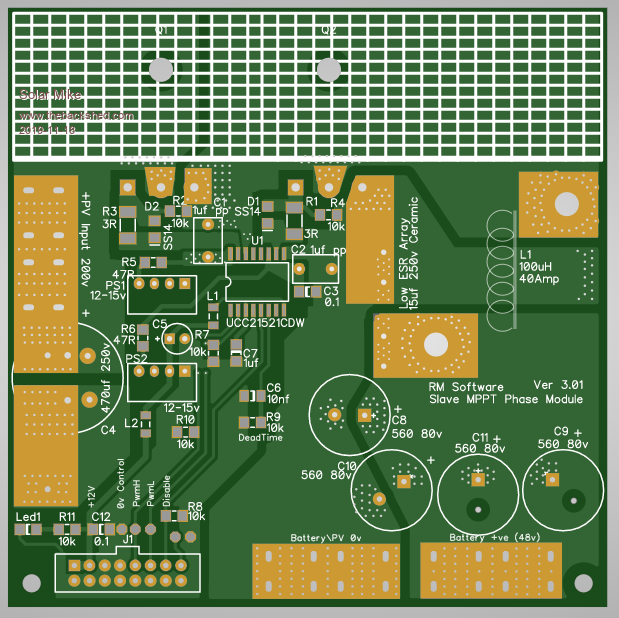 Bottom: 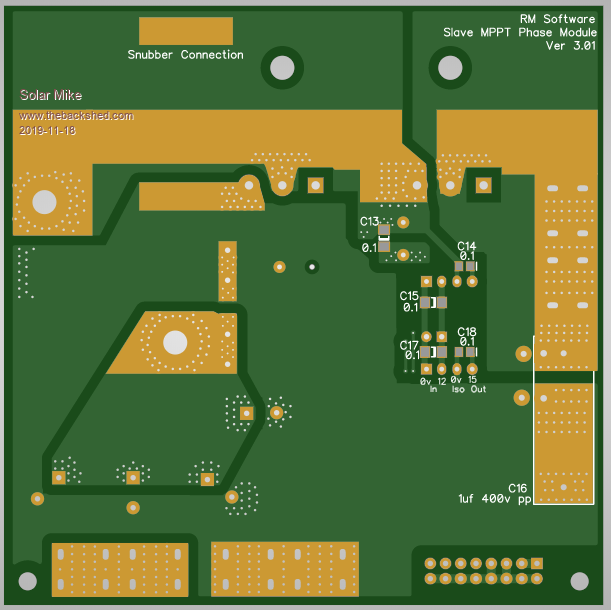 I need to make a mother board now with CPU etc, This will also have some larger Bulk input capacitors on the PV side, output ones don't matter so much here as the battery is a near infinite capacitor. Cheers Mike Edited 2019-11-18 06:12 by Solar Mike |
||||
mackoffgrid Guru Joined: 13/03/2017 Location: AustraliaPosts: 460 |
How many turns do you need on that core for 100uH? |
||||
| Solar Mike Guru Joined: 08/02/2015 Location: New ZealandPosts: 1123 |
You can work it out from their spec sheet, about 25T, waiting for items to arrive so haven't tested with my Inductor saturation curve tracer. Mike |
||||
| mackoffgrid Guru Joined: 13/03/2017 Location: AustraliaPosts: 460 |
Thanks, yes I was showing my laziness  |
||||
| Solar Mike Guru Joined: 08/02/2015 Location: New ZealandPosts: 1123 |
Fixed my input stuff up, all 4 PWM phase signals are now on the ribbon cable, solder blob link on the pcb selects wanted input; this is fed into InA on the chip, InB is switched by a mosfet to get an inverted input, the chips dead time fixes any crossovers. All changes on the top layer. 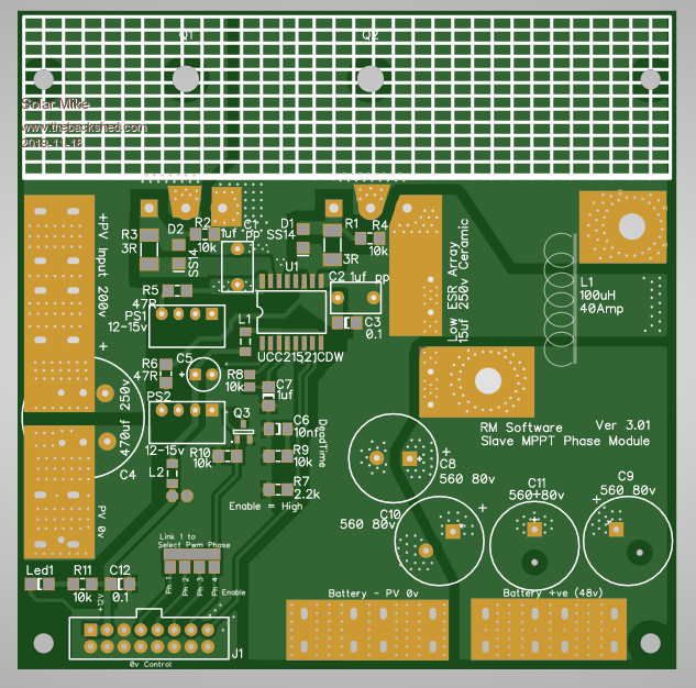 Note if the DW version of the UCC21521 is used, the PS1//2 can be changed to 12-12 volts, I'm using CDW variant as the DW doesn't seem to be available in small quantities. Time now to draw up a schematic. Cheers Mike Edited 2019-11-19 05:43 by Solar Mike |
||||
| rogerdw Guru Joined: 22/10/2019 Location: AustraliaPosts: 794 |
Fascinating thread Solar Mike. Just so I get this straight ... this project takes the output from one PV array and charges one 48V battery ... but uses four separate modules to share the charging process ??? The reason for splitting it up between multiple boards is simply to reduce the size and cost of the Buck coil and associated components ... four small systems is much smaller, cheaper and easier to build than one large one ??? Cheers, Roger Cheers, Roger |
||||
| Solar Mike Guru Joined: 08/02/2015 Location: New ZealandPosts: 1123 |
One PV Array, correct; the battery bank voltage can be anything you want really, I have optimized components for 48v, however there is no reason why you cannot use 12\24\48\96 etc. The buck\synchronous rectifier modules are designed to be modular, as up to four can be used on the one host controller; they all share a common CPU host PCB (yet to be designed) for control. The host board has four 10bit resolution PWM outputs at 62 Khz, each output is on a different switching phase, so when combined the system is effectively equivalent to a 248 Khz PWM buck converter, but with a lot lower losses and better efficiency. Each buck module is good for 30 amps (single layer PCB) although the mosfets are rated way higher than this. At 48v x 30 odd amps approx 1500 Watts, so depending on the size of your PV array, up to 4 modules may be used to extent the charge current as required. On another thread "3Kw Controller" I designed one that would charge to a similar output 120-150 amps. The buck inductor weighs about 2kg and I had to import the bare cores from the USA, this makes it somewhat hopeless and expensive to build. Big currents = high I^R losses and specialized components, smaller modules can use readily off the shelf cores that are cheap and easy to wind; if your array is only a couple of KW then only two modules can be used - much simpler in concept. MPPT controllers have gotten cheaper over the past few years (the Chinese ones anyway) 60 amp auto switching 12/24/48v are available here in NZ for <$600, all well and good until they blow up and then become unfixable doorstops. This design I hope will will allow something to be DIY that can be repaired. I need 6 of these controllers, thus motive for designing my own. If you can build your system with correctly match PV array to battery voltage then pure a PWM controller would be a better option and way less expensive to make. Cheers Mike |
||||
| rogerdw Guru Joined: 22/10/2019 Location: AustraliaPosts: 794 |
Thanks for filling in the blanks Mike ... it's always helpful when you hear the back story. Took me a while to go through the other thread and I can see the reasoning behind the direction you're taking. Love the idea and will be excited to see the finished design. Pretty sure I could make use of the finished product too. Being able to be fixed if it fails is huge as well. Staggers me the amount of expensive stuff that just ends up in landfill. On a good day I have sometimes repaired boards that cost $7-8000 to buy new. I probably don't charge as much as I should, but it's still an awesome feeling knowing that it wasn't all just trashed for want of a handful of parts and a days labour. What are the ideal parameters eg for a 48V battery system. In looking at available secondhand panels, there's quite a variation in output and open circuit voltage figures ... hard to know just how important it is to aim for one or the other. Thanks again for all the insight. Cheers, Roger Cheers, Roger |
||||
renewableMark Guru Joined: 09/12/2017 Location: AustraliaPosts: 1678 |
If you want to Pwm try to get Max amps voltage close to 30v, so when you series 2 then you have 60v or so. If you plan to use a fork battery it will likely have bulk absorb voltage of 57.6v, so you are not missing out on much of the peak power. When it's at float @54v you are not using all the power on tap so it doesn't matter. When you start drawing a load the controller will up the pwm cycle to keep voltage up to the 54v. Many controllers will have a start charge process again voltage, so if it gets drawn down too far it will start at bulk then go through the routine from the start. The little Mad Pwm board is great, but make sure you put in on a whopper heat sink and perhaps allow for fans. Something like this is pretty good.  If you go mppt it doesn't matter as much, just check the specs of the controller Edit, whoops, sorry Mike I shouldn't have got your thread off track like that. Edited 2019-11-21 07:27 by renewableMark Cheers Caveman Mark Off grid eastern Melb |
||||
| Solar Mike Guru Joined: 08/02/2015 Location: New ZealandPosts: 1123 |
No problem there Mark, I was going to say much the same thing, 24 volt rated panels that have a Vmp of 30 volts are readily available up to 285 watt output; so two in series is a pretty good match for a 48 volt bank. However the common used 4mm^2 cable in any length above 10 meters is only good for 18 amps before the power losses increase too much, means every 4 x 285w panels is a separate cable run; going to Mppt has advantages in that higher input voltages can be used with less current; so greater number of panels and power output per cable run, or longer distance. But hey if you can get hold of second hand panels at cheap prices, then a little wasted power is of little consequence, sadly NZ doesnt have a second hand market of cheap PV stuff as there were and nor will be any subsidies for PV, so the uptake is pretty low. Cheers Mike |
||||
| rogerdw Guru Joined: 22/10/2019 Location: AustraliaPosts: 794 |
Thanks for the confirmation of the ratings Mike. Regarding cabling, I wonder if it's possible to pick up some heavy second hand cable to do some of those low voltage parallel runs to reduce the voltage drop. I bought some excellent priced multicore cable to run some dmx lighting once and saved hundreds. Cheers, Roger |
||||
| Solar Mike Guru Joined: 08/02/2015 Location: New ZealandPosts: 1123 |
Whatever you use has to be UV protected, the "solar" cable has a very thick tough black UV proof insulation, would be hard to beat... I have used 6mm mains rated conduit wire in the past for long runs buried in the ground inside a plastic water pipe. Mike |
||||
| rogerdw Guru Joined: 22/10/2019 Location: AustraliaPosts: 794 |
Makes sense ... I might make a visit to some of the local scrap yards and see what's lying around ... though I'm not going to flaunt the law too much in that area. Thanks. Cheers, Roger Cheers, Roger |
||||
| Solar Mike Guru Joined: 08/02/2015 Location: New ZealandPosts: 1123 |
About time I got back to this again, the host multi-phase controller pcb has finally been designed, 4 phases have been implemented allowing use of 1 to 4 mppt buck converter boards mounted above the main pcb. Vertical copper bars bolt to the 120 amp connectors on the host pcb, the power boards connect to these via right angle connectors. Host board has a Picaxe 28X2 cpu module via plug on connector, allowing a swap out with another cpu for experimentation later, the 4 phase PWM output runs at 62 Khz at 10 bit resolution, with a solder link on the power modules to select the required phase drive. I have added modules for remote battery voltage sense and 1-Wire local area network. Multiple controllers can be slaved to a master for common control of voltage and charge end points. I2c and serial outputs can be connected by wire headers. Added a couple of relays for activation when in "Bulk" or "Float" charge states. Will post the circuit soon as I get it done. 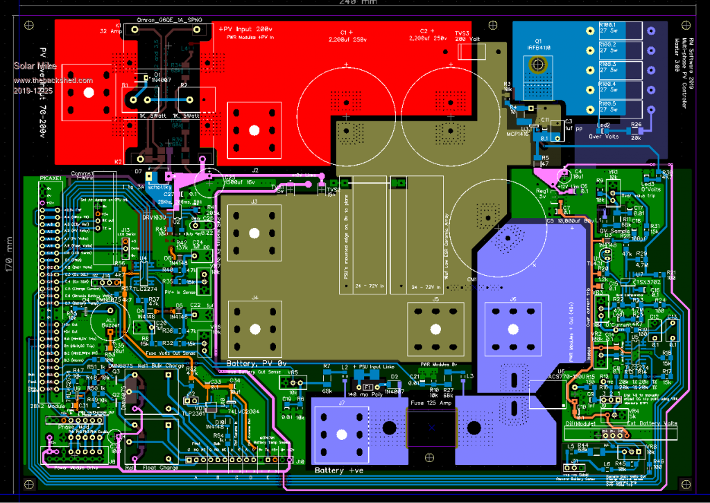 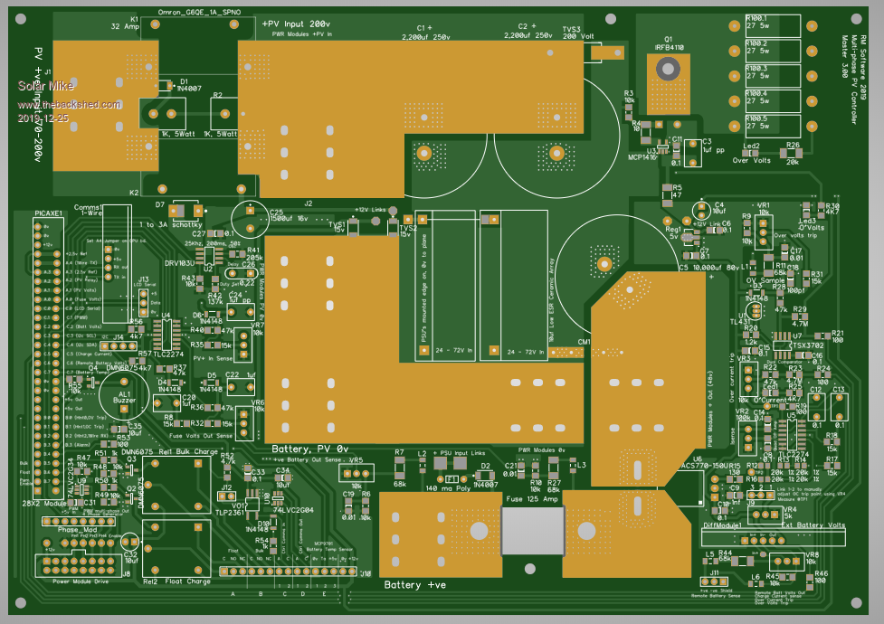 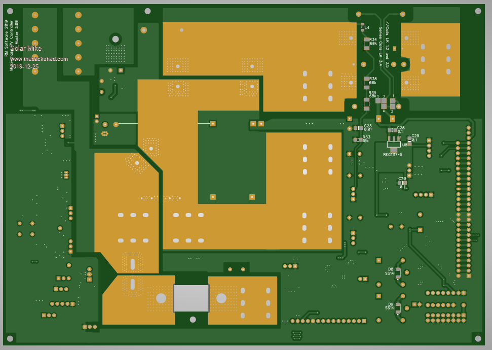 Cheers Mike |
||||
| mackoffgrid Guru Joined: 13/03/2017 Location: AustraliaPosts: 460 |
Looks Nice Mike. Looking forward to the schematics  Cheers Andrew |
||||
| Solar Mike Guru Joined: 08/02/2015 Location: New ZealandPosts: 1123 |
Will make a start on the schematics: The 4 phase circuit has a number of Schmitt trigger inverters acting as 2uS delay units, with delay taps at 4,8,12 uSec. Implemented on a small pcb that plugs into the main controller board. Such a simple circuit means the minimum PWM duty cycle cannot be smaller than 2uS, with PV voltages approx 2-3x the battery voltage, this shouldn't be a problem as long as the PWM frequency sits around 62 kHz; any higher and the delay sections will need reducing in time, possibly requiring more of them. 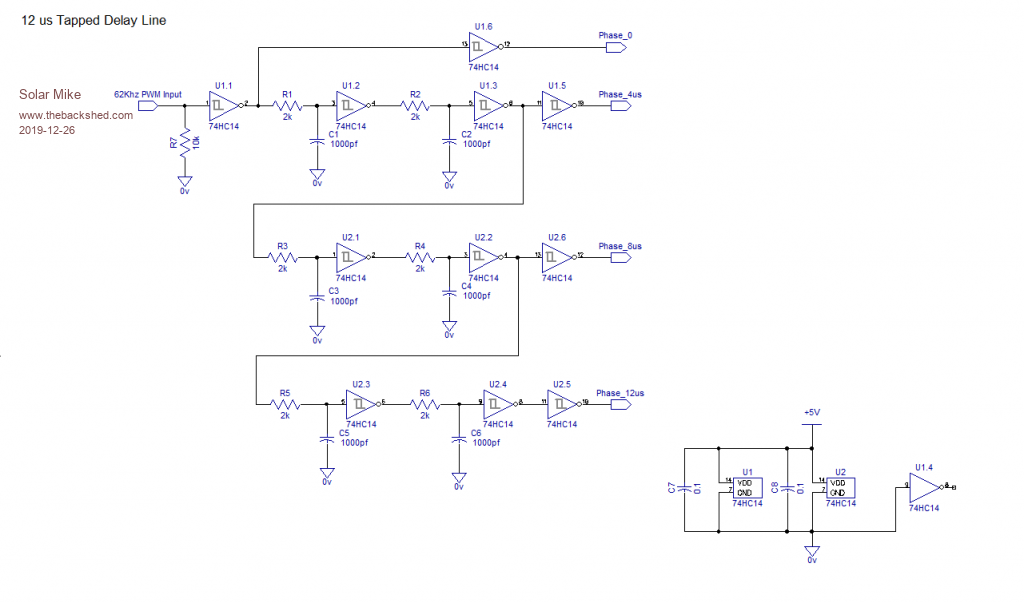 Main Controller Circuits: MP_Controller_P1.pdf MP_Controller_P2.pdf Will add others later today. Cheers Mike Edited 2019-12-26 21:50 by Solar Mike |
||||
| Solar Mike Guru Joined: 08/02/2015 Location: New ZealandPosts: 1123 |
Gerbers have been sent to JLCPBC for the host pcb, phase delay and mppt power boards, hopefully will get them back early in the new year. Here are some details on the design. Referring to schematic xxxx_P1.pdf: PV array power connects to the bulk supply caps C1,2 on the host main board via two high current Omron G6QE 12v power relays, contacts in parallel, the contacts are bypassed by pre-charge resistors to allow near fully charging of bulk caps prior to energizing the relays, this prevents excessive arcs. A specialized PWM relay driver chip is also used here to lower the coil power dissipation, all under control of the CPU; have gone down this route for controlling the PV isolation from the battery rather than use of several paralleled mosfets, as I consider it to be more reliable, especially when subjected to possible high voltage spikes from lightning or similar; costs are similar either option. Common output current sensing is done with a ACS770-150U, the circuit also allows for the bi-directional 150B, depending on what is available. These sensors get hot up around 150 amps and perhaps not the best option for higher power, will see how they go, one of the ones that clamp around a copper bus bar would be a perhaps a better solution. There is an over current trip circuit with an interrupt signal to the cpu; may or may not do anything with this; originally I was going to wire it to a logic gate to turn off the PWM drive, independent of cpu. The over voltage trip circuit is there to protect the components should the battery connection open (fuse or breaker popping etc) when under high charge currents. A clamp circuit is activated that shunts a 10 amp load across the output and concurrently interrupting the cpu; this should protect things from excessive voltages whilst the cpu is still processing to shut down the output. Referring to schematic xxxx_P2.pdf: Rail to rail op-amps used for cpu voltage sensing, each connected as a low pass filter to reduce switching noise and present a low impedance input to the cpu adc inputs. An opto-coupled isolator is used to allow one way communications from a master controller to others connected to the same battery bank, this will allow all controllers to switch state at the same voltage and current control points, eg. bulk charge voltage, float etc. Some commercial units have this feature and seems like a good idea. Two output relays, one for bulk charge state, other for float are there to allow external circuitry to use these control states for application of external battery loads etc. A differential instrumentation pcb module is used to sense the battery terminal voltages for more accurate measurement by cpu, the 1-Wire module is used for network comms to allow any site external devices to monitor the charge controller status (future requirement). Two headers on the main board have I2c and serial data for connection to some sort of local LCD display. For battery temperature sensing, have used an MCP9701 chip, rather than say the 1-wire DS18B20 sensors, they are accurate and reliable; if using the Picaxe cpu, it has to dynamically change its cpu clock to communicate with the 18b20 sensors, completely stuffing up the PWM drive output. More on the mppt power boards to come... Cheers Mike |
||||
| Solar Mike Guru Joined: 08/02/2015 Location: New ZealandPosts: 1123 |
Finally drawn the schematic of the power module, and to my relief, it does match the pcb layout, as the gerbers have already been sent off to production... 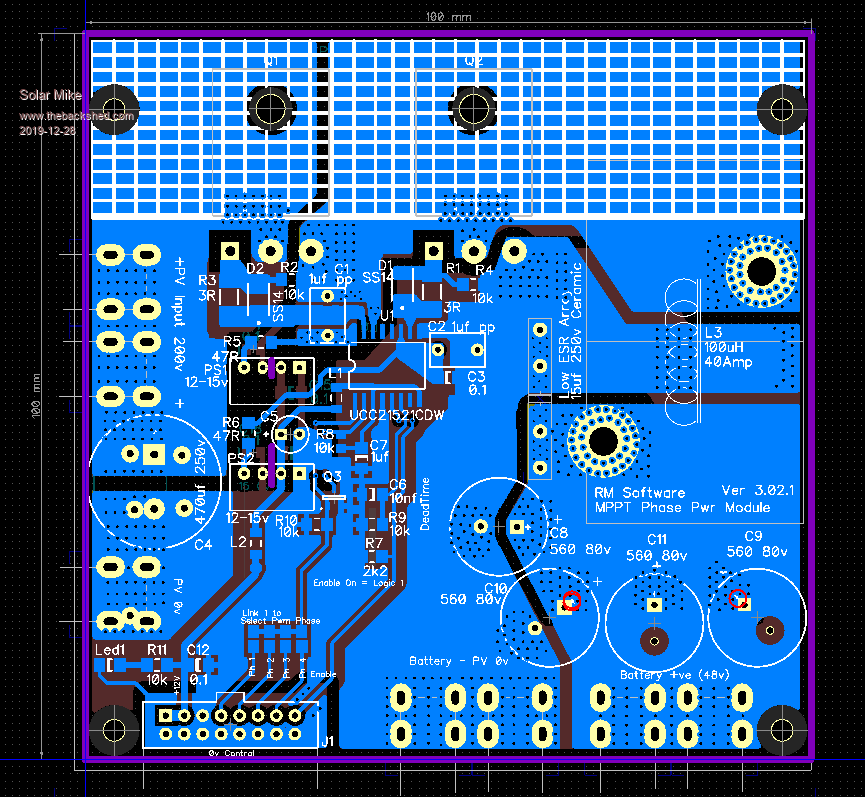 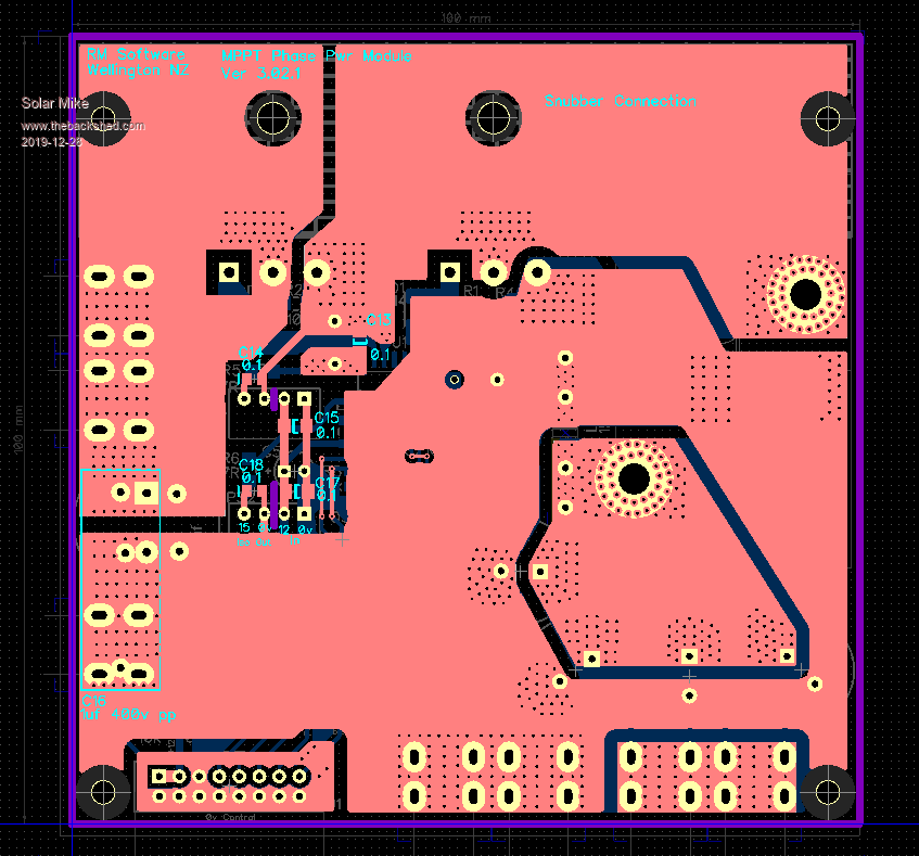 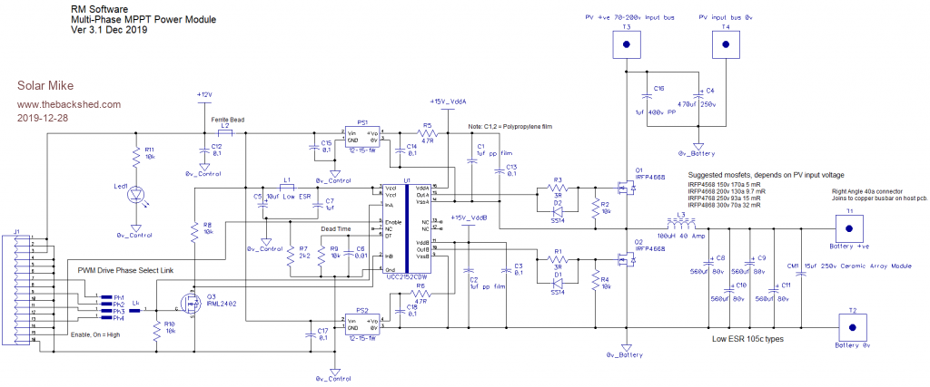 Starting on the LHS ribbon cable connector, all 4 PWM phases are input, a link selects the required phase. Heart of the circuit is the UCC2152 half bridge chip, its inputs are 5v logic compatible and fully isolated from the output power stages, output dead time set by R9 and is guaranteed under all input conditions, allowing input "B" to be created as an invert of the "A" input by using a mosfet. This makes driving the buck inverter power stage much easier and way less prone to spurious inputs blowing up the mosfets. Different versions of the chip have differing under voltage lockout sensing for the power stages, one I'm using here requires 15 volts as I couldn't get any of the 12v versions, think they are available now though, simple change the PS1,2 switch supplies to 12-12 type. The enable input when taken to logic High turns on the output stages, so in conditions of discontinuous PWM drive, the CPU can simply turn off the mosfets so preventing any large reverse currents flowing in the output buck inductor. The buck outputs from all power modules connect by copper busbars to the host controller board, this board also has larger bulk supply and output caps to augment the ones on each phase module. Note: This circuit is all theoretical, none of it has been tested and relies heavily on cpu software yet to be written. Cheers Mike |
||||
| Warpspeed Guru Joined: 09/08/2007 Location: AustraliaPosts: 4406 |
Mike, if you do an analysis of what happens when the MPP solar panel voltage is well matched to the battery voltage, the controller should only ever be seeing very high duty cycles during bulk battery charging. When the battery hits full voltage and the controller goes into absorb mode, both the duty cycle and current through the controller taper off. In other words, the lower mosfet can be replaced by a shottky diode with minimal penalty. Under heavy loading the shottky diode conduction period and losses are absolutely minimal. As the system throttles back, the shottky duty cycle certainly increases, but the current through it also decreases. Using a diode instead of the lower mosfet eliminates a lot of potential problems and blow up modes, while having less effect than you might expect on total heat dissipation at full power or efficiency. I believe the slight tradeoff in overall power dissipation is well worth the long term reliability gained through eliminating some really nasty potential failure modes. Cheers, ĀTony. |
||||
