| |
  Page 2 of 2 Page 2 of 2 |
| Author |
Message |
mikeb

Senior Member

Joined: 10/04/2016
Location: AustraliaPosts: 173 |
| Posted: 06:59am 10 Oct 2019 |
 Copy link to clipboard Copy link to clipboard |
 Print this post |
|
Probably better if the board design had the Analaogue Ref and Ground pins brought out seperately.
Boost converters are the hardest to filter as they draw very peaky currents on their input side which is probably what you are seeing on the scope. Doesn't matter what caps you put on the input side. Boost converters generally need LC networks comprising a couple of poles. This requires calculation.
I'm with Peter on this one. Ditch the converter on the display and feed with a cleaner 5V supply.
Regards, Mike B.
@Gizmo
Still haven't found a 'Donate" button.
There are 10 kinds of people in the world.
Those that understand binary and those that don't. |
| |
PeterB
Guru

Joined: 05/02/2015
Location: AustraliaPosts: 639 |
| Posted: 08:01am 10 Oct 2019 |
Copy link to clipboard |
Print this post |
|
I don't have a problem with SMPS. I use them a lot. The switching does cause small, very sharp pulses due to stray C. The main current however should be reasonable i.e. a ramp up - down, in an ideal world that is.
The problem shoots has is his power supply is not able to provide sufficient current so it collapses. It is possible that his display is faulty and drawing too much current.
A nice big C will prove / disprove this idea.
Peter |
| |
shoots

Newbie

Joined: 31/07/2011
Location: AustraliaPosts: 32 |
| Posted: 02:10am 16 Oct 2019 |
Copy link to clipboard |
Print this post |
|
So the state of play is...
I found the issue did not change regardless of power supply or battery size. It is definitely related to the backlight's boost circuit.
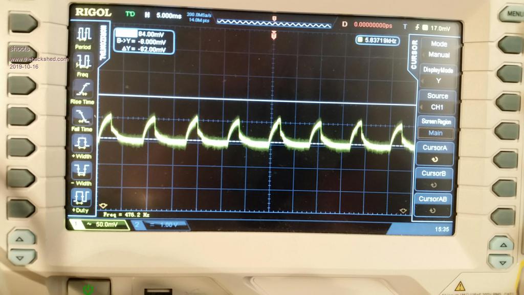
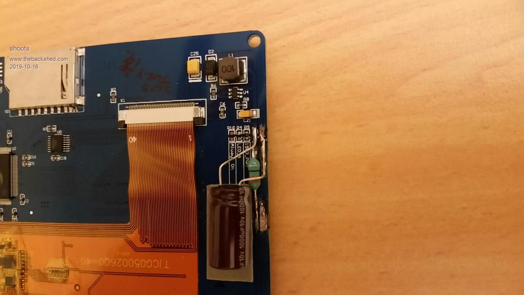
I ended up following Brian's suggestion and cut the track on the line supplying the backlight circuit and inserted a 15uH inductor in line with that supply and put a 1000uF electrolytic after the inductor to ground. This improved the noise situation considerably from around 700 mV p-p to approx 50mV. I think I can live with that. I have done this to two of the touchscreens in have and so far no problems. There is about a 0.2 V volt drop across the inductor which has not affected things at all. Trying to get the noise down lower resulted in too much volt drop and affected the screen's performance.
In case others have a similar issue I will post a shot of the resulting noise and the modification to the screen:
I also implemented a exponential smoothing of the analog input which made a significant difference. A few good notes on this are at:
https://www.megunolink.com/articles/coding/3-methods-filter-noisy-arduino-measurements/
BTW I have been using megunolink for plotting the data out of the MM using a spare serial port and it has made life easier for tuning.
I wonder if anyone has used a 5" touchscreen of a different brand to the one pictured which is from AliExpress? I have seen another brand but I have doubts that its pinouts will match the express 100 PCB.
Thank you for your advice guys. This has been another good learning experience.
Cheers,
Peter |
| |
CaptainBoing

Guru
Joined: 07/09/2016
Location: United KingdomPosts: 1985 |
| Posted: 04:26am 16 Oct 2019 |
Copy link to clipboard |
Print this post |
|
Nice one.
Couple of weeks ago, I replaced a busted PSU in a MSF clock radio with a mains - 12V switching module (fitted nicely in the space available). After, radio was fine but it couldn't hear the MSF signal so couldn't set its clock... had to redesign using a good old fashioned transformer based design. Job done.
All this is a sobering tale of modern designs/approaches - horses for courses! Excellent diagnostics and happy result. Did you play with smaller bypass caps in parallel with (after) that bruiser? Say, 10-100nF just to see if you can trim away a bit of that 50mV... find a value that fits your specifics here? Just a thought. |
| |
shoots
Newbie
Joined: 31/07/2011
Location: AustraliaPosts: 32 |
| Posted: 05:28am 16 Oct 2019 |
Copy link to clipboard |
Print this post |
|
I did try numerous capacitor sizes before and after the inductor but no improvement. Finally had to draw a line and carry on with the rest of the project. I would definitely like to source an alternate touchscreen for future projects. Of course if a project does not have any analog elements to it then not a problem. |
| |
Bowden_P
Senior Member
Joined: 20/03/2019
Location: United KingdomPosts: 162 |
| Posted: 01:48pm 27 Oct 2019 |
Copy link to clipboard |
Print this post |
|
Hi Shoots,
It sounds like you have/had a similar issue to me. I've just started looking at my problem, and will post a new topic.
I'm pleased everyone managed to sort the issue - it is frustrating when a project gets "hijacked" by an unexpected problem - if only for a while!
With best regards, Paul.
Edited 2019-10-28 00:04 by Bowden_P
Nothing so constant as change. |
| |
shoots
Newbie
Joined: 31/07/2011
Location: AustraliaPosts: 32 |
| Posted: 12:01am 28 Oct 2019 |
Copy link to clipboard |
Print this post |
|
Hi Paul,
I would be interested to see how it goes for you. Once you post a new topic put the link here as I would like to follow how it works out. Yes it is frustrating and time consuming- blows out the development time budget.
Regards,
Peter |
| |
Bowden_P
Senior Member
Joined: 20/03/2019
Location: United KingdomPosts: 162 |
| Posted: 11:52pm 30 Oct 2019 |
Copy link to clipboard |
Print this post |
|
Hi Peter,
My topic is :-
"Using a Load Cell "Click" module with Explore 100 board."
http://www.thebackshed.com/forum/ViewTopic.php?PID=141673#141673#141673
With best regards, Paul.
Nothing so constant as change. |
| |
BrianP
Senior Member
Joined: 30/03/2017
Location: AustraliaPosts: 292 |
| Posted: 03:09am 31 Oct 2019 |
Copy link to clipboard |
Print this post |
|
My 2c worth...
I would not run any switching regulator (backlight supply) from the same bus as the processing circuitry - just asking for trouble especially with ground loops.
In other words, a separate supply for the backlight (a pain I know...)
B |
| |
| |
Page 2 of 2 |
