
|
|
Forum Index : Electronics : What inverter style would you build if starting a new system in 2020
| Author | Message | ||||
renewableMark Guru Joined: 09/12/2017 Location: AustraliaPosts: 1678 |
The Ali boards seem not to have totems on the smaller boards, but if you look at the bigger ones they mostly do. here here here here Cheers Caveman Mark Off grid eastern Melb |
||||
| Warpspeed Guru Joined: 09/08/2007 Location: AustraliaPosts: 4406 |
There are several quite different ways to drive a pwm bridge, quite apart from the actual physical circuitry. First there is bipolar drive, in which each half bridge is continuously driven with a full pwm sine wave. All four mosfets are driven constantly all of the time with pwm, which generates two anti phase sine waves at the transformer primary. That is probably the best, but switching losses are going to be higher and all four mosfets need efficient high frequency high powered gate drivers which costs more. Then there is unipolar drive, and there are different versions of that. Two mosfets are driven with high frequency pwm, and the other two mosfets are switched hard on, and hard off, at only 50Hz. The two mosfets being pwm'd can either be the two lower mosfets, or the upper and lower mosfets on one side of the bridge. There can be problems if you start mixing driver boards with power boards if the power board has a wimpy gate drive circuit for one pair of the mosfets. If all four gate drivers are capable of high powered gate drive, then it should be o/k. Mad's totem pole driver power board is certainly a step forwards and recommended if you are going to go with pwm. But as you try to switch more and more current by driving more parallel mosfets, the Gods of fire and destruction may become angry. Cheers, ĀTony. |
||||
| nickskethisniks Guru Joined: 17/10/2017 Location: BelgiumPosts: 462 |
Hi, If I need to choose again I would do a Warpverter I think, but I still don't have one. I will make one in the future  WHY? I would chose a Warpverter because it "can" be more powerfull, I trust the design more, it's not simple to switch high current at high frequency, the warpverter topology solves that for a bit I think. BUT: The Ozinverter is cheaper/kW , smaller/kW, I think also less Idle current. I have made a verry powerfull OzInverter (clockfrmann boards), and I'm running it more then a year now (1900kWh), now the whole house is running on it. Load to 6000W is no problem at all. I'm not pushing it further because I know I screwed up the electric conductivity between mosfet and heatsink. (heatsink is used as conductor). I still need to check/improve that. I only had 2 faulty mosfets and drivers, and that was my mistake during testing, I made a ground short circuit with high side scoop measuring. I still use the ribbon wire between power and drive electronics, I use 6 irfp4110 mosfets on each H-bridge leg. And my inductor is way to small for the loads I put on. I must say it only sees temperaturs between 12 and 20░C. The only thing it doesn't like is the startup of the mobile airconditioner and hairblowers and heatguns, oh he really hates it! ( terrible noise) I think they cut the sinewave in nasty stuff. I made a few changes to the original: IR2010 drivers, 15V (12v original?) supply to gatedrivers, I think I have put a diode between control electronics and power electronics, so it shuts down on a proper way. I also used small buck converters (5 and 15V) to reduce idle power even more. With what I read and followed here from other builders I think the nanoverter combined with the totempole drivers powerboard is a more improved robust version. But the original ozzinverter is easiest, less components to solder/program. Important is to use genuine parts! A lot of problems could be avoided if you use genuine parts from the start. Oh I configured my sun 2000G grid tie inverter, so it's in parallel with my OZinverter. The sun2000G inverter senses if there is powerdraw, if there is powerdraw the sun2000g inverter will sent back that power (max1800W). Example if there is a load of 3000W, the grid tie inverter will put in 1800W, the ozinverter will only do 1200W. The sun2000g will even see the other grid tie inverter and will not give power if there is not more power needed. A picture of the monster (the way it looks): 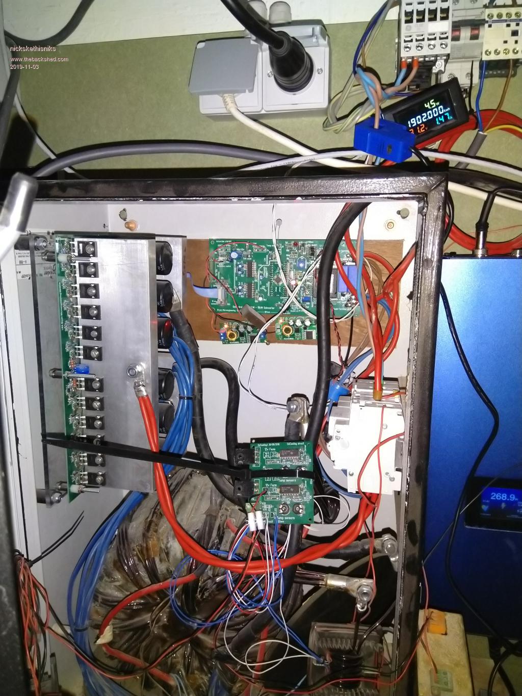 btw, the watt meter is confused because of the backfeeding... it sees 1.4Amps but only sees 7Watts? Edited 2019-11-03 09:40 by nickskethisniks |
||||
| rogerdw Guru Joined: 22/10/2019 Location: AustraliaPosts: 904 |
Thanks for the no BS reply Mark. Another 4 or 5 hours reading to catch up on the history and I am slowly 'getting' it. Yes, sorry I stand corrected. I did read that first thread ... but in it you mentioned a link to another (51 page) thread ... so I got engrossed in that as well. I also read all of the 'Inverter PCB's' thread ... another marathon, but eye opening as well. Kinda surprised that no-one uses circuits much ... have no idea how you get all your board layouts, but no circuits.  I fix circuit boards for a living ... and I get zero support as far as any technical info goes ... but until I draw out a circuit (at least of the affected areas) ... it can often take me ages to sort a board out. Over the years as my circuits become more complete ... my understanding of the boards improves enormously and my repair time improves heaps as well. I keep reminding my wife that if I kark it ... she needs to find someone to sell my filing cabinets of info to ... they are worth a small fortune. I also agree that I'd like to build my own. If I'm going to build something, it might as well be worthwhile ... what do they say ... go big or go home!! So, if I had to make a decision right now, I'm kinda leaning towards an 8kW inverter with a rewound double stack AeroSharp 3kW torroid transformer ... to create my own mini-grid ... ... a 48V 600Ah forklift battery ... a standard GTI or 2 ... 10kW+ of secondhand panels ... one of Mad's regulator kits to look after the GTI's and battery recharging Sooner or later I'm going to have to stop reading and start doing ... though I have finished unwinding the first torroid. The bottom 2 windings weren't obviously burnt ... but had a smell that made me very suspicious ... and because I wouldn't have been confident re-using that wire I was pretty rough in winding it up. Then I discovered on some of the sharper bends, the enamel just flaked off ... so clearly it was stuffed. Another clue was that the mylar tape between those 2 layers had turned to flakes and just crumbled away. Wasn't brown or anything ... just destroyed ... yet the layer covering the former just below it is like new still. Cheers, Roger |
||||
| rogerdw Guru Joined: 22/10/2019 Location: AustraliaPosts: 904 |
Thanks for your input too nickskethisniks. Very interesting to hear your views and your first hand experience. Nothing beats personal experience, no matter what 'theory' or opinion says. Gutsy looking torroid in your build and nice clean looking output board. I'm surprised by the smaller size of your heatsinks compared to most that have been shown ... how have you got on with heat ... or are you in a cooler area? Point taken about genuine parts too. Will need some help to know exactly what suppliers can be trusted and who to avoid. Thanks. Cheers, Roger Cheers, Roger |
||||
| rogerdw Guru Joined: 22/10/2019 Location: AustraliaPosts: 904 |
This last week has been a real education for me learning about all the different types and styles of inverters, so I appreciate your help Tony in explaining so many of the differences. Not sure if others are the same ... but understanding the back story of how things came to be, helps enormously. I don't know that I will ever have any ridiculous great loads for any system I build ... so pwm should be quite feasible ... though I clearly want to keep those "Gods of fire and destruction" right out of the picture. Cheers, Roger Cheers, Roger |
||||
| Warpspeed Guru Joined: 09/08/2007 Location: AustraliaPosts: 4406 |
Mad's boards definitely seem to be the best way to go right now, but although the circuit board is very important, a great deal of the important stuff is not mounted on the actual circuit board. We all tend to use whatever parts readily come to hand to build our inverters, and the actual physical layout and what might seem like very minor details can build in some unsuspected and difficult to nail down problems. A schematic circuit diagram just tells us what is connected to what, and it might seem that as long as everything is connected as per the circuit diagram it should work. But switching 100 amps at 20Khz plus is a very serious business, and even a couple of extra inches of wire in the wrong place can introduce noise and voltage spikes into the grounding system. As Mark says, some have had great success with the Ozinverter, and others have not. That is taking nothing away from the Oz design. What he has achieved is monumental and a huge credit to him. But its not all as simple to reproduce as it first appears. Cheers, ĀTony. |
||||
| renewableMark Guru Joined: 09/12/2017 Location: AustraliaPosts: 1678 |
Be aware Roger before you plan everything make sure it's all legal. Some don't seem to care, but I do. For instance if you plan to use a GTI backfeeding, most of them operate at higher voltages than a handyman is allowed to wire. So then you'll need a sparky to wire it up and put his certificate of electrical safety on it (and what it's connected to) A few problems there, the GTI, panels and even the racking and clamps must all be on the CURRENT CEC approved list, or a sparky won't touch it. Secondly I doubt if a sparky would hook up a GTI to a home made inverter. I got around all that by wiring everything ELV under 120v dc and found a GTI that operates at ELV voltage as well (Latronics PV edge). However I have not had success getting it to run as it comes up with grid fault, it and another one do the same, but when tested on the grid power they both operate fine. So there appears to be something to do with the nanoverter control board that doesn't allow it to backfeed...not sure on that, but that is what I have seen so far. I was going to test my machine with the Mad control board but I just want to keep that one running as it powers the house, I don't need that one blowing up on more experiments now. But having said that, the Mad control board has operated just fine backfeeding others setups, so it is proven to work doing so. In my case, the Warp unit will be the primary machine, so I'm concentrating on that now. The other will be a very capable back up unit. Cheers Caveman Mark Off grid eastern Melb |
||||
| nickskethisniks Guru Joined: 17/10/2017 Location: BelgiumPosts: 462 |
Maybe something with earthing or fase/line and neutral wire. I had that problem as well with my inverter. Checking earth and switch neutral and line. |
||||
| rogerdw Guru Joined: 22/10/2019 Location: AustraliaPosts: 904 |
Thanks Tony. I certainly got the impression that the peripheral stuff can cause all sorts of changes and potential issues. That means the more of a build that is identical to a previous successful build, the more chance for success ... and certainly reduces any variables to work through if problems arise. I understand your point about cct diagrams ... but I'm often surprised when I draw out a circuit (reverse engineer a board) ... I get a completely different view of how it works ... and potential reasons for the failure I'm trying to address become blindingly obvious. In some cases I've been fixing a particular board for years ... just fixing the obvious faults ... but then a different fault causes me to have to draw out more of, or the rest of the circuit. I then finally realise how the thing actually works ... with a complete picture in my head instead of piecemeal ... and I see it in a completely new light. Occasionally then, I can implement a modification or two to improve reliability ... and have been very successful in doing that. I love circuits. Regarding Oz, I have enormous respect for him and wish he was still around the forum dropping pointers and tips in all the areas he's had experience with ... and providing inspiration to the likes of me. Cheers, Roger |
||||
| rogerdw Guru Joined: 22/10/2019 Location: AustraliaPosts: 904 |
Yeah, that's why I'm doing as much homework as I can before I make a decision. No point going down a particular path if it's a definite no-no. Being in the electrical and electronics trade is very helpful as well, having built up a network of contacts with skills in different areas to call on for their expertise. Cheers, Roger Cheers, Roger |
||||
| renewableMark Guru Joined: 09/12/2017 Location: AustraliaPosts: 1678 |
You don't need a GTI to backfeed anyway. You can series 2 panels for max amp output at 60V and PWM that to charge a 48v battery. The bulk/absorbtion charge is 57.6V anyway, so you are not really losing much efficiency when in this charge state anyway. When in float mode @54V......who cares, you are just wasting power then anyway. That Mad controller will do both, top half does PWM which I use for 60v input. The bottom section is for GTI operation. You can use either or both at the same time. Problem with doing PWM is there are lots of wire runs, and they need to be in conduit too BTW (just like the higher voltage GTI wiring) Then you'll need 2 or 3 of the 8 capacity circuit breaker boxes, outputs going to buss bars and onto the PWM controller then on to battery. If you go down this route plan it out on your wall very well, mine started small and got added to, so it all had to be stripped and started again, and moved to another wall. The good part about PWM is you can do it all yourself and add to it when time, parts, funds are available. Cheers Caveman Mark Off grid eastern Melb |
||||
| Warpspeed Guru Joined: 09/08/2007 Location: AustraliaPosts: 4406 |
The circuit designer has a big advantage in that the whole thing follows through from some original plan or concept, and than slowly evolves through testing. Anything that appears not quite right is fixed. A resistor may be replaced with one of higher wattage, extra bypass capacitors added here and there, and so on. It all works fine, and the schematic is published, and others try to copy the design and immediately strike problems. This happens all the time, its par for the course. I am greatly embarrassed by the completely unexpected transformer capacitance problem with the Warpverter. But at least its now a clearly defined and understood problem, that we will definitely find the solution for. Especially with very high powered pwm, there can be far more subtle and nasty problems with things like running very large heat sinks "live" by connecting the drains of high frequency mosfets direct onto the heatsink. Then running extra long extended ribbon cables between control board and power board with the ribbon cable draped directly over the heat sink. The original designer would probably never imagine doing such a thing, but what is obvious to the designer may not be so obvious to the person building his own "version" of the original design. He may even bolt his microcontroller board right on top of the same heatsink and not give the possibility of an extreme radiated electrical noise problem any thought at all. So success or failure can be a chance combination of many very subtle and less obvious effects, that an experienced constructor would regard as just common sense and good workmanship, without really thinking about it too much. I have enormous respect for Oz too, but can easily understand that once his wonderful creation was thrown to the great unwashed public, he rapidly lost control of the narrative. All the ensuing problems and arguments and bickering would have frustrated a saint. Cheers, ĀTony. |
||||
| nickskethisniks Guru Joined: 17/10/2017 Location: BelgiumPosts: 462 |
Yes, good notice, my mosfets are bolted too 12mm thick aluminium, since the system is in my basement it Ānever sees temperatures over 18░C. They get warm but never too hot to touch. Constantly running it around 3000W is no problem. For high peak load it has enough thermal mass to collect. I "was" planning to bolt some fins on it, but it works fine like this... Not recommended for hot climate. The frontdoor has 2 fans of 120mm 5W, that are running from the moment my inductor reaches 30░C. The inductor is @ this moment the weakest link in my system. Edited 2019-11-05 17:50 by nickskethisniks |
||||
| rogerdw Guru Joined: 22/10/2019 Location: AustraliaPosts: 904 |
Thanks Mark, there's certainly a heap of alternatives. I've worked out an area of wall under some stairs in the shed, below the roof where I plan to fit the panels. I can see that with lower voltages there needs to be a lot more cable runs ... but can't be avoided. You wrote "Then you'll need 2 or 3 of the 8 capacity circuit breaker boxes" ... I'm not sure what you meant there. Ok, there's a lot in there to absorb. I had wondered about the length of ribbon flopping about just waiting to pick up something ... but I don't know enough about high powered fet ccts to have thought about your other points. Easy enough to avoid if thinking about it before starting ... hopefully! Good summary on Oz ... that makes sense. Thanks for the explanation ... though I don't think I'll get away with that for mine as my shed will get a lot warmer than 18░C in summer. Try 40░C+ Your inductor is in the square former at bottom right corner? Cheers, Roger |
||||
| renewableMark Guru Joined: 09/12/2017 Location: AustraliaPosts: 1678 |
You need some kind of disconnect for the panels. Breakers are the most economical and best suited I reckon. You can use some kind of switch, but you must (legally) have some form of disconnect for the panels. Like this Or this for inside Keep in mind I'm talking about Victorian ELV regulations that were checked when mine got done. That may not be up to date, and will also vary state to state. Edited 2019-11-06 06:17 by renewableMark Cheers Caveman Mark Off grid eastern Melb |
||||
| brucedownunder2 Guru Joined: 14/09/2005 Location: AustraliaPosts: 1548 |
I just finished a disconnect box for my 2 strings of 1Kw panels . 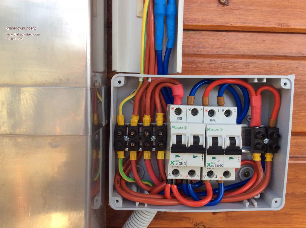 Tried to resize , sorry. Bruce Bushboy |
||||
| rogerdw Guru Joined: 22/10/2019 Location: AustraliaPosts: 904 |
Thanks for the clarification Mark. I hadn't worried too much about those details yet, though was aware that there are a whole heap of rules regarding isolation switches for panels ... and then the controversy of where those switches should be ... on the roof where no-one can get to them (and they catch fire regularly) ... or at ground level somewhere accessible. And then being in SA ... our rules are just as likely to be 180 degrees opposite!!! Thanks Bruce, I was going to ask for photos of layouts etc once Mark started mentioning them. That's a very tidy (and tight) connection box. Cheers, Roger Cheers, Roger |
||||
| Clockmanfr Guru Joined: 23/10/2015 Location: FrancePosts: 437 |
Hi Roger, Inside of a working OzInverter. Keep the cables tidy and air space between the cables, especially the power cables, or parasitic frequencies will be induced when cables get close to each other. I thought it was standard common sense to keep AC high voltage separated, AC low voltage separated, High voltage DC power cables separated and low voltage DC cables separated. Etc etc. The ribbon cable between control and power board is short, and should be no longer than 200mm and should have air space around it. And a Utube vid of a OzInverter ...... https://www.youtube.com/watch?v=5s9B3RTF1QA https://www.youtube.com/watch?v=5s9B3RTF1QA 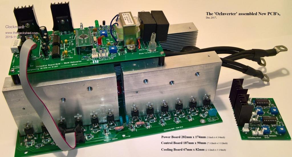 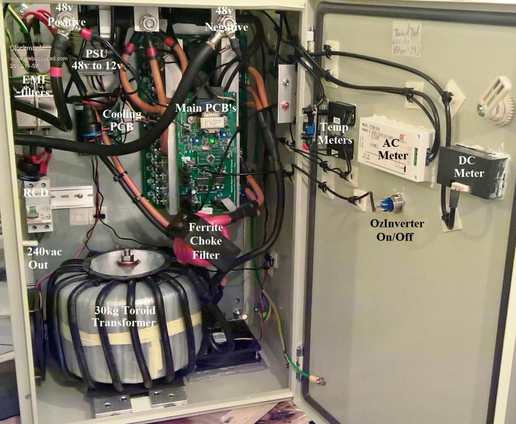 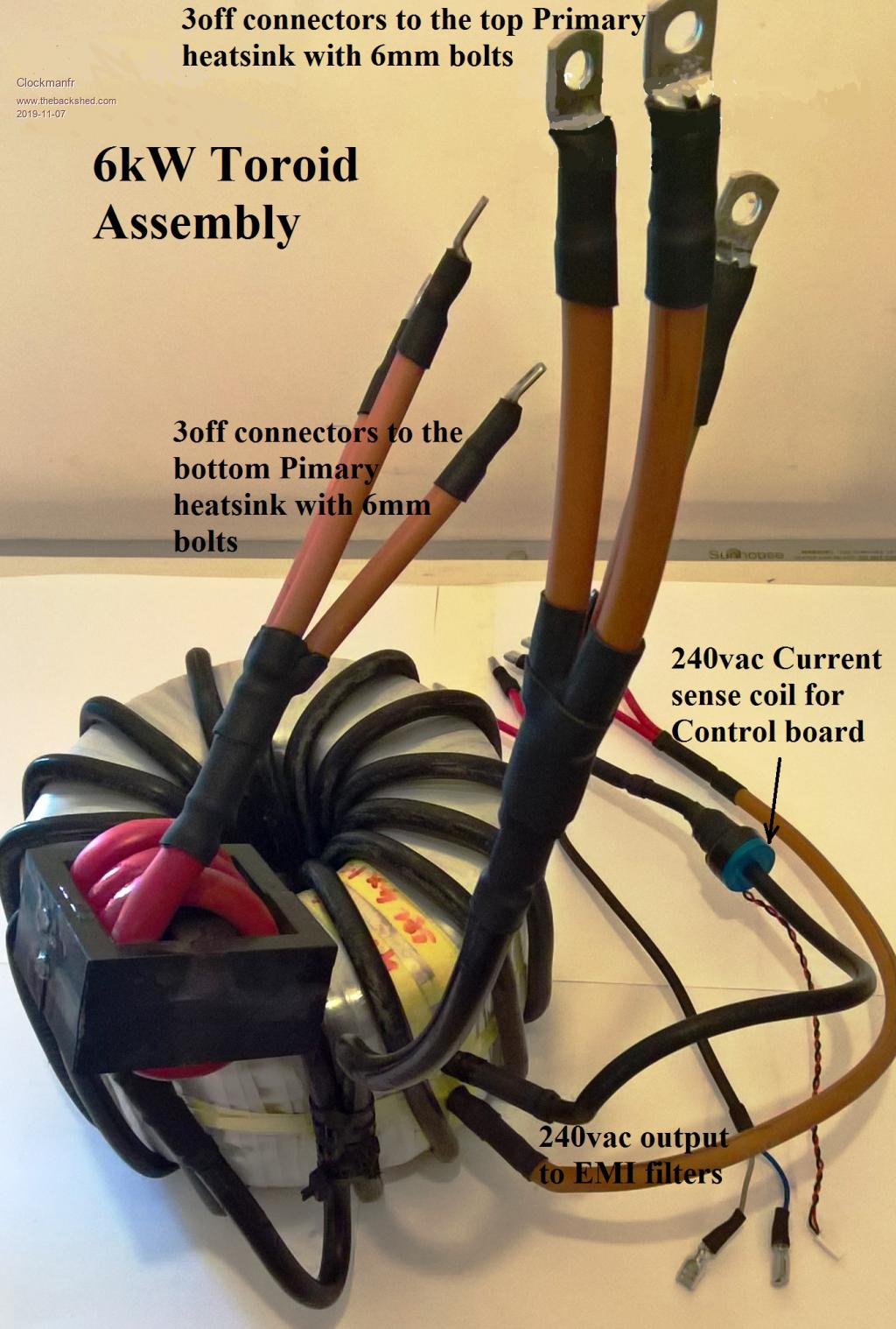 I trust this helps. Edited 2019-11-07 18:50 by Clockmanfr Everything is possible, just give me time. 3 HughP's 3.7m Wind T's (14 years). 5kW PV on 3 Trackers, (10 yrs). 21kW PV AC coupled SH GTI's. OzInverter created Grid. 1300ah 48v. |
||||
| rogerdw Guru Joined: 22/10/2019 Location: AustraliaPosts: 904 |
Thanks Clockman, that does help. I had seen a couple of those photos and videos before but it's good to refresh my memory. I had also wondered about the physical layout and location of wiring etc. Also about fitting shielding perhaps ... or even those rectangular ferrite blocks to go over the ribbon etc etc. For you to mention that it's important to keep the ribbon at 200mm or less ... I'm assuming you suspect that interference can potentially get into the ribbon and create false triggering of fets on the OP board?? Still, if you and oztules had already built quite a number ... a direct copy should make it possible to replicate. Cheers, Roger Cheers, Roger |
||||
| The Back Shed's forum code is written, and hosted, in Australia. | © JAQ Software 2025 |
