
|
|
Forum Index : Microcontroller and PC projects : Help needed with MM voltage measurements
| Author | Message | ||||
OA47 Guru Joined: 11/04/2012 Location: AustraliaPosts: 1050 |
I have been developing a project and the portion I am having trouble with is an auto-ranging volt reading circuit. Here is what I have: 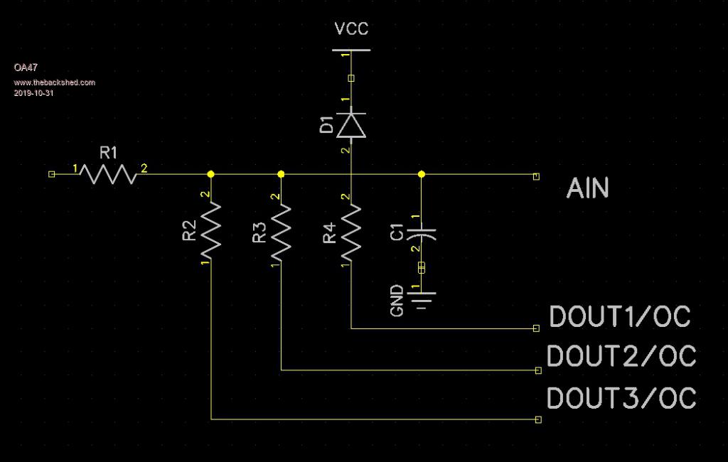 The resistor values that I have been playing with are : R1=1Mohm R2=1Mohm R3=100K R4=10K I chose these values as I wanted to present the highest impedance to the measured voltage without the internal impedance of the PIC chip having too much effect. In the software I initially ground DOUT1 having a 100:1 drop, then if the measured voltage is less than say 2V ground DOUT2 and put DOUT1 to high impedance. If the voltage measured is still less than 2V ground DOUT3 and put DOUT2 in hi z. The issue I have is that over the ranges I loose linearity so I need to somehow calculate the resistance values so that when it switches between ranges I don't loose accuracy. I can calibrate the reading in software at the high end of each range but there is a major discrepancy when switched to a lower range. Any help in achieving this would be greatly appreciated. OA47 Edited 2019-10-31 07:38 by OA47 |
||||
| Bowden_P Senior Member Joined: 20/03/2019 Location: United KingdomPosts: 174 |
Hi OA47, Is the leakage of D1 and/or C1 contributing to the range non-agreement when switching ranges? While the leakage on the highest "R4" range may not matter much, as you switch in higher value resistors AIN becomes increasingly higher impedance, so messing up the range agreement? I believe the PIC will have ESD diodes to Vdd and Vss on AIN and the DOUTn/OC pins, also a source of leakage. The leakage of the semiconductor junctions may be a more-or-less constant value, but C1 voltage dependent. With best regards, Paul. Nothing so constant as change. |
||||
mikeb Senior Member Joined: 10/04/2016 Location: AustraliaPosts: 178 |
The maximum impedance on the input of a PIC pin, configured as an analogue input, is 10K. You have, in a sense, an RC network with a very long time constant, which varies with range switching. See the relevant PIC datasheet which shows the 'model' of the PIC's analogue converter module. Connect your conditioning circuit to the input of an opamp and feed the opamp output into the relevant PIC pin. This will provide a very low 'source' impedance to the analogue input pin. Note that the analogue Vref and ground pins, on most development boards I have seen, are connected to the Digital Supply and hence your readings will be unstable to say the least. You will have to do averaging of some sort in software to make the reading as stable as you can but it won't be ideal. Some dithering is to be expected. Regards, Mike B. There are 10 kinds of people in the world. Those that understand binary and those that don't. |
||||
| Turbo46 Guru Joined: 24/12/2017 Location: AustraliaPosts: 1693 |
Hi OA47, I second mikeb's comments above and: Are you aware that your division ratios are not proportional? The formula for calculating the Vin to Vout ratio is: Vout = Vin * Rb/(Rb+Ra) where Ra is the input resistor and Rb is the shunt. That would make the ratios 1 to 0.5, 0.0909 and 0.0099 The logic zero output voltage of the micro may not be exactly zero I suspect and may add an offset to the readings You may need to use FETs as switches and you could beef up the ground connection to the analogue ground pin on the micro. Bill Keep safe. Live long and prosper. |
||||
| mikeb Senior Member Joined: 10/04/2016 Location: AustraliaPosts: 178 |
Hi OA47, One other quirk, I have heard of and makes perfect sense, is that the protection diode to V+, and also within the PIC analogue model, can rectify high frequency noise on the input and superimpose a standing (albeit small) dc bias on top of your wanted signal. Did you think measuring a voltage with a PIC was going to be simple ?  Have fun. Remember. None of us no everything but all us us no something about something. We are all just a keystroke away from each other. @ Gizmo Well done on the new site. Thankyou for all your efforts.  Still can't find a donate button though.  There are 10 kinds of people in the world. Those that understand binary and those that don't. |
||||
bigmik Guru Joined: 20/06/2011 Location: AustraliaPosts: 2981 |
Hi OA47, What about if you drive mosfets to GND then you should have a better result? Mind you I dont use mosfets myself, purely because my brain is so old it froze in the bipolar transistor era. Kind Regards, Mick Mick's uMite Stuff can be found >>> HERE (Kindly hosted by Dontronics) <<< |
||||
| PeterB Guru Joined: 05/02/2015 Location: AustraliaPosts: 669 |
G'Day All Mick. The PIC uses FETs on its outputs so adding more will not help. The output impedance of the voltage divider is too high for the PIC input impedance as noted by mikeb so some sort of buffer is needed. Leakage could be a problem via diodes, electros, whatever. But it is do-able. Peter |
||||
| zeitfest Guru Joined: 31/07/2019 Location: AustraliaPosts: 683 |
I saw something similar which worked ok, at the cost of more complexity. It had an opamp voltage follower with a quad analog switch ic in the back loop, so that the switch selected one of four resistors which then set the ratio. |
||||
| bigmik Guru Joined: 20/06/2011 Location: AustraliaPosts: 2981 |
G�day Peter, I stand corrected then.. You could use small relays in that case like the ones in a dip 16 package.. Mick Mick's uMite Stuff can be found >>> HERE (Kindly hosted by Dontronics) <<< |
||||
| mikeb Senior Member Joined: 10/04/2016 Location: AustraliaPosts: 178 |
Bigmik, and zeitfest, offer excellent suggestions. As you are only doing one of these devices you may well be able to calibrate out any error caused by using the PIC outputs to switch your divider to ground. Relays are a perfectly adequate method but you need to keep in mind selection. Your circuit does not provide enough 'wetting' current for the contacts. Because you are switching extremely low currents contact resistance will be your worst enemy. Relay contacts tend to build up an oxidation layer on their face, which requires the above mentioned 'wetting' current referred to earlier, so you have a few choices to make. The DIP package is a good one as it is hermetically sealed. So are reed relays. To go one step further I would suggest a relay with gold flashed contacts. One step further is a relay with a bifurcated contacted arrangement. this ensures that the contacts have a wiping action as they come together. This has been proven over many years to be very effective at eliminating the oxide layer. However, this arrangement is only generally used in relays which are not hermetically sealed. Many professional grade metering applications use relays so it is a perfectly valid design. Is measuring voltage easy ?  Depends on the results you expect. Depends on the results you expect.@ Gizmo Still can't see a donate button. Regards, Mike B. There are 10 kinds of people in the world. Those that understand binary and those that don't. |
||||
| Turbo46 Guru Joined: 24/12/2017 Location: AustraliaPosts: 1693 |
I would be doing as zeitfest suggests: A FET input op amp using a 4066 analogue switch for switching scales. That would probably mean a negative supply and level shifting to switch the 4066. Analogue circuitry wasn't meant to be easy. @0A47 Comments? Keep safe. Live long and prosper. |
||||
| Mixtel90 Guru Joined: 05/10/2019 Location: United KingdomPosts: 8911 |
I think I'd have done this the other way, as the PIC input is current driven really. Fixed resistor to ground and series resistors shorted out by reed relays. Possibly a non-inverting buffer between the resistor network and the PIC input. Mick Zilog Inside! nascom.info for Nascom & Gemini Preliminary MMBasic docs & my PCB designs |
||||
| Volhout Guru Joined: 05/03/2018 Location: NetherlandsPosts: 5931 |
hi oa47, The circuit you draw is definitely possible. Most autoranging multimeters use similar circuitry. If this works for you depends on the accuray and linearity you want to achieve. 1/ most ad convertors sample and charge a small capacitor inside the silicon , that is used during the conversion. If that capacitor must be charged fast because you need fast adc speed, you need a low impedance at the adc input. If you have time enough, you can in most cases program the adc to use a longer sampling time, and input impedance can be high. I currently have an arduino monitoring discharge of a supercap powered realtime clock. The adc input in a stupid arduino uses far less than a microamp. You can create a low impedance by putting an external capacitor at the adc input, and still use a high input impedance. But the capacitor and high input impedance cause a rolloff at higher frequencies. This must be carefully tuned to your application. The external cap, and internal sampling capacitor, will share charge during the sampling period, so your error depends on the ratio between sampling capacitor and external capacitor. The diode you have in your design can be usefull, but will leak. Depending on the input impedance that may cause a temperature dependent offset. Choose a low leakage diode, or omit it. Typically microcontrollers have protectiondiodes that can handle several miliamps. You may be safe if the inout resistor is high enough. Internal diodes also leak btw.. You do not need to use accurate resistors, all calibration Can be done in software. You only need to look at the pins that drive the resistor dividers. They should be really high impedance when off, or input. And the output resistance when on varies with temperature. To avoid measurement errors, the fet output impedance should be low in respect with the resistors. If you start doing the math, you will see that it may work, but if you aim on 12 bit resolution, with 2 decades of programable attenuator you are talking 19 bit effective. 20 bit is 1 :1000000. You will see this is not achievable with only an MX170. If you are aiming at 8 bits resolution an 1 decade of programable gain, it may very well possible without external amplifiers an reed contacts. Do the math, based on required adc rate, chip output impedance ang input impedance on gpio pins, sampling capacitor value, and analog bandwidth. I am curious what you come up with. Maybe your application can be done. Like my huntron tracker could be done with relatively high impedance adc attenuator. Volhout PicomiteVGA PETSCII ROBOTS |
||||
| OA47 Guru Joined: 11/04/2012 Location: AustraliaPosts: 1050 |
Thank you everyone for the feed back and information. I thought that I would take the challenge and see if I could compensate for errors with software. I used my trusty 0-40V lab power supply and my 3.1 digit multimeter to log values from the PIC. I firstly did 1.0 volt steps up to 40.0V with the 1M/10K divider, then the same steps using the 1M/100K divider. Lastly I did 0.10V steps from 0.1V to 6.0 volts using the 1M/1M divider. I used a speedsheet program to trim a factor, correction and offset for each of the ranges and mapped the error margin. Apart from the voltages less than 0.6 volts using the 1M/1M divider I was able to keep the error at less than 1% and able to auto range and keep meaningful readings. Here is the code I am experimenting with: Sub Voltmeter LogV=1 WatchDog Off CLS Local integer offset Do Pin(15)=0:Pin(16)=1:Pin(21)=1 'Initial set to 200V setting If Touch(x) <> -1 Then Exit Sub ' exit if the screen has been touched Text 150, 20, "Voltmeter", CM, 2, 1, RGB(Blue) ' Autoranging here Vm=Pin(24): Pause 100 Volts=103*Vm-(0.005/Vm)-0.2 If Volts < 20 Then Pin(16)=0:Pin(15)=1:Pin(21)=1 '20V setting Vm=Pin(24): Pause 100 Volts=12*Vm-(0.012/Vm)-0.8 BL=1:BEEP End If If Volts < 2 Then Pin(21)=0:Pin(15)=1:Pin(16)=1 '2V setting Vm=Pin(24): Pause 100 Volts=2.2*Vm-(0.165/Vm)-0.28 BL=1:BEEP End If If Volts > 9.999 Then V$=Str$(Volts,2,2) Else V$=Str$(Volts,1,3) Text MM.HRes/2, MM.VRes/2 - 30,V$ , CM, 3, 1, RGB(white) If Mid$(V$,2,1)="." Then Offset=95 If Mid$(V$,3,1)="." Then Offset=155 Circle Offset, 130, 6, 0, 1, 0, RGB(white) Text 150, 160, Date$, CM, 2, 1, RGB(Green) Text 150, 190, "UTC "+Time$, CM, 2, 1, RGB(Green) Offset=0 DrawButton 0, 0, 0, 210, 90, 30, RGB(Red), "EXIT" DrawButton 1, 0, 110, 210, 100, 30, c.ghosttext, "HOLD" DrawButton 2, 0, MM.HRes-90, 210, 90, 30, c.ghosttext, "LOG V" ' CheckButtonRelease btn If LogV=1 Then 'Log every 10 seconds If Right$(Time$,1)="0" Then Print "UTC,";Date$;",";Time$;",";V$ Pause 800 EndIf If LogV=2 Then 'Log every minute If Right$(Time$,2)="00" Then Print "UTC,";Date$;",";Time$;",";V$ Pause 500 EndIf If LogV=3 Then 'Log every hour If Right$(Time$,4)="0:00" Then Print "UTC,";Date$;",";Time$;",";V$ Pause 500 EndIf Loop WatchDog 4000 End Sub OA47 |
||||
| Volhout Guru Joined: 05/03/2018 Location: NetherlandsPosts: 5931 |
Not Bad ! The 1M/1M may in the end not be so usefull as measuring range. You may be able to use the 1M/100k hardware and use some "ranging" in software to achieve a 0-6V range. Did you have any idea where the error on the lower 0.6V of the 1M/1M comes from ? Is I diode leakage? Then it will be temperature dependent (heat the diode). Is it internal diode in the MX ? Is it the ADC input impedance ? (remove the input signal and see what offset you get at zero). If that is the case you must also see it at other input voltages. But in the end it could give you a usable range. You can not measure negative voltages...~ Is that a problem ? Volhout PicomiteVGA PETSCII ROBOTS |
||||
| The Back Shed's forum code is written, and hosted, in Australia. | © JAQ Software 2026 |
