
|
|
Forum Index : Microcontroller and PC projects : Spa Controller
| Page 1 of 2 |
|||||
| Author | Message | ||||
| Phil23 Guru Joined: 27/03/2016 Location: AustraliaPosts: 1667 |
Hi All, Been running my Spa Controller for a few years on an E28 Backpack which had all pins used. Plan on upgrading it to an E-100. (Arrived last week Grog.  ). ).Because of the pin shortage I built a second MM on Vero board & mounted it in the heat pump I repurposed from a hot water system. All that one does is monitor 5 thermistors & a flow meter, sends the data back to an E64 over a 433MHz link when polled, which then sends out data packets to 2 other E100's also on 433. With the extra pins available on the E100, I could run the thermistors there, but would prefer not to be cabling the analogue sensors an extra 2 or so meters. The Flow meter I will move & add a second. ATM the one in the heat pump outputs the data on Com1 to a HC-11. If I decided to connect the Com port of that MM directly to the new E100, would TTL serial levels over 2 metres of so be too much? If so what would be the simplest module to add to the Com ports at each end for reliable coms between the two. Thanks Phil. Edited 2019-11-28 12:17 by Phil23 |
||||
TassyJim Guru Joined: 07/08/2011 Location: AustraliaPosts: 6269 |
2M should be OK but I tend to use RS485 modules now-a-days to be sure. Jim VK7JH MMedit |
||||
| PeterB Guru Joined: 05/02/2015 Location: AustraliaPosts: 655 |
G'Day Phil & Jim I agree RS485 is good stuff. This problem got well and truly discussed some time ago when AndrewG (I think) had a similar problem. Peter |
||||
| Tinine Guru Joined: 30/03/2016 Location: United KingdomPosts: 1646 |
Doesn't sound like full duplex is required but a couple of MAX491s would do the trick and they are virtually plug and play. In my case, I always want the master to be able to talk to the slaves, even if a slave is in the middle of responding. So the E100 TX line is dedicated. The RX is a shared response line. At 2m, I probably wouldn't bother with biasing or terminating. Regards, Craig Edited 2019-11-28 21:11 by Tinine |
||||
| lizby Guru Joined: 17/05/2016 Location: United StatesPosts: 3362 |
I can't say that I've tested extensively, but I have run MMBasic serial output over 50' of Cat5/6 cable without issues, with moderately complex VT100 screen formatting. PicoMite, Armmite F4, SensorKits, MMBasic Hardware, Games, etc. on fruitoftheshed |
||||
| Phil23 Guru Joined: 27/03/2016 Location: AustraliaPosts: 1667 |
Think I've probably got a few more of these somewhere. Currently using one on another MM to read the 3 Eastron Modbus power meters. Suitable? Can't remember how the A-B-Gnd bit went & recall a termination resistor on the furtherest meter. Think that module has it's own from memory, 120ohm? 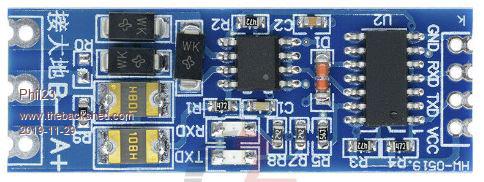 Phil. |
||||
| Phil23 Guru Joined: 27/03/2016 Location: AustraliaPosts: 1667 |
Also got a few of these at the time, 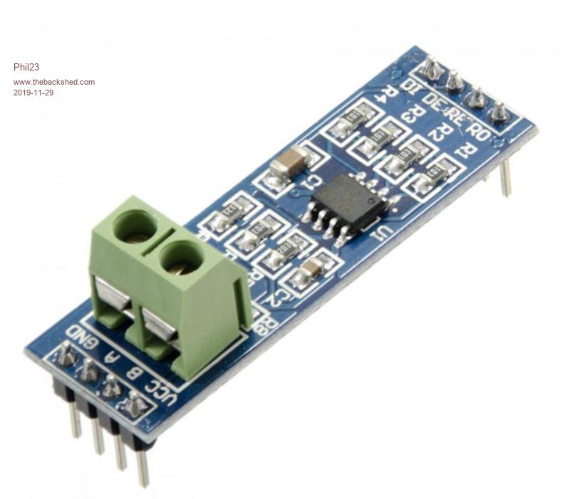 https://core-electronics.com.au/ttl-uart-to-rs485-converter-module.html Think I used the others for some reason relating to the Auto transmit/Receive function of the HW-0519. https://www.sunrom.com/p/rs485-ttl-module-with-protection-auto-transmit/receive switching Don't think I ever got my head around head the use the others with Modbus slaves. Or the pinout requirements. DI, DE, RE, RO. Phil. |
||||
| Turbo46 Guru Joined: 24/12/2017 Location: AustraliaPosts: 1639 |
Phil This may help RO (Receiver Output) Connects to a serial RX pin. RE (Receiver Enable) Active LOW. Drive LOW to enable the receiver. DE (Driver Enable) Active HIGH. Typically jumpered to RE Pin. DI (Driver Input) Connects to serial TX pin. The 120 ohm resistor R7: If using in a multi-drop configuration, the modules on the two ends of the line should keep these resistors. Modules in the middle of the line should have these resistors removed to prevent loading the lines too heavily. The signal wires should be a twisted pair, shielded for long runs and there should be a common ground. Vcc is 5v but mine run quite happily at 3.3v The Micromite can supply a DE signal (connect DE to RE) but it is the wrong sense (see the manual). Rather than use that pin and an inverter I use an output pin to supply the DE signal, set it high to transmit the message, then, after the message has been sent, set it low to enable reception. Apart from that it is treated as though it is a normal RS232 device. Bill Keep safe. Live long and prosper. |
||||
| TassyJim Guru Joined: 07/08/2011 Location: AustraliaPosts: 6269 |
I actually use these RS422 modules so that they are plug and play and handle full duplex so I can load programs easily. 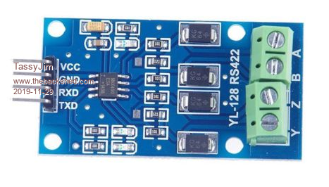 Jim VK7JH MMedit |
||||
| Phil23 Guru Joined: 27/03/2016 Location: AustraliaPosts: 1667 |
So Basically this.... Phil. |
||||
| Turbo46 Guru Joined: 24/12/2017 Location: AustraliaPosts: 1639 |
Yes, but the trap is that you have to wait until the entire message has been sent before lowering the 'DE' pin (and closing the port). For example: Geoff has changed the behaviour of the CLOSE command in later versions of MMBasic so a CLOSE will not occur while a message is still being sent but lowering the 'DE' must wait. Bill Keep safe. Live long and prosper. |
||||
| Tinine Guru Joined: 30/03/2016 Location: United KingdomPosts: 1646 |
I don't believe that those modules require the DE signal, do they? I believe that they do it automatically when sensing a TX. If you go one-to-one with full duplex on something like MAX491s, you simply tie the DE pins high. This way, it's no different to using TTL RX & TX but now you have differential transceivers. Regards, Craig Edit: Referring to TassyJim's module. Edited 2019-11-29 16:11 by Tinine |
||||
| Turbo46 Guru Joined: 24/12/2017 Location: AustraliaPosts: 1639 |
The one in Phil's second photo uses the MAX485. This is the one to which I was referring. Here is the circuit. 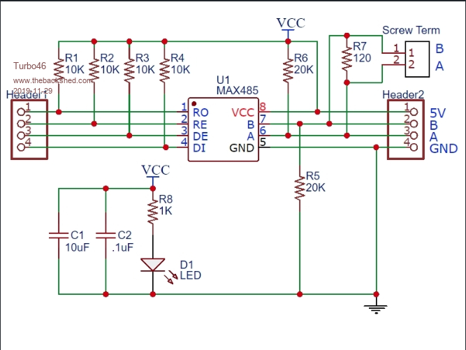 There are no smarts. you need to control the transmit/receive switching. I believe the one in the first photo does do it automatically. Bill Keep safe. Live long and prosper. |
||||
| Tinine Guru Joined: 30/03/2016 Location: United KingdomPosts: 1646 |
Ah, maybe it's because TassyJim's appear to be using the MAX490 which don't have enables. From what I can make out, this means that the devices can never go into low power mode(?). Probably more of an issue with battery powered devices. Not an issue in my case so I might try some MAX490s, next time around. Regards Craig |
||||
| TassyJim Guru Joined: 07/08/2011 Location: AustraliaPosts: 6269 |
The ones I am using are very good for one to one but not much use for multidrop where you need to put the transmitters into high Z. Jim VK7JH MMedit |
||||
| Tinine Guru Joined: 30/03/2016 Location: United KingdomPosts: 1646 |
Auto Enable 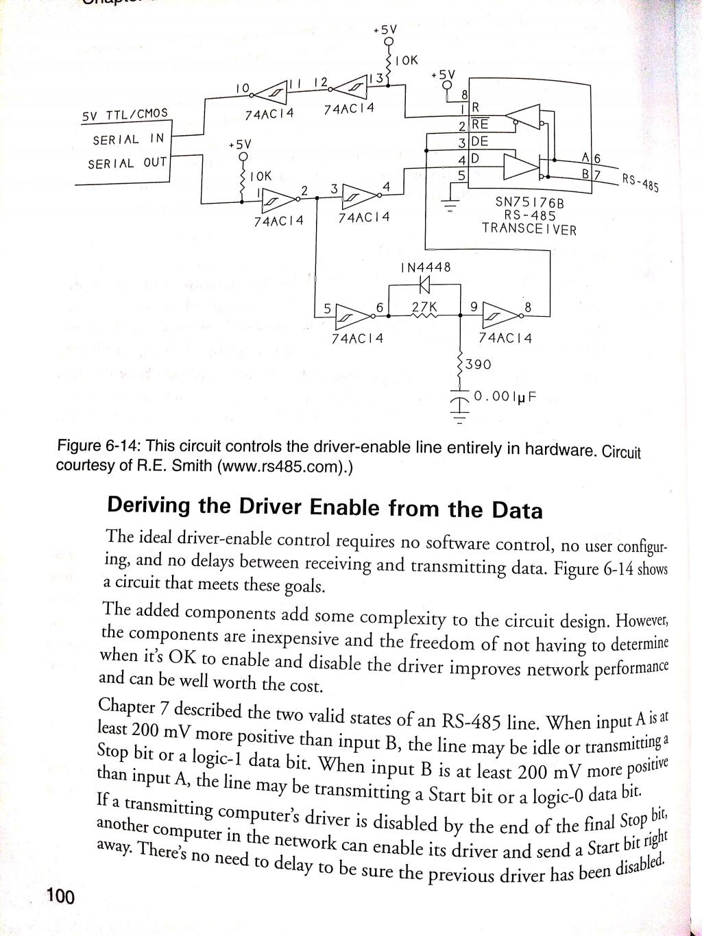 Cheers, Craig |
||||
| Tinine Guru Joined: 30/03/2016 Location: United KingdomPosts: 1646 |
 |
||||
| Turbo46 Guru Joined: 24/12/2017 Location: AustraliaPosts: 1639 |
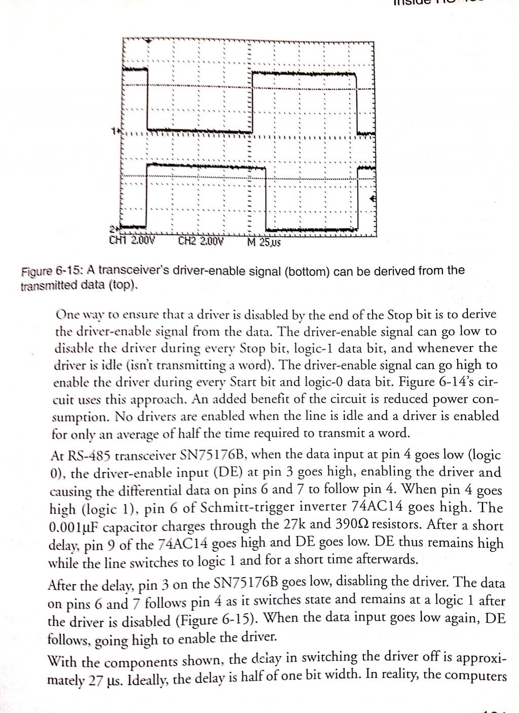
If I am understanding the above circuit correctly, the driver IC is only enabled when the Serial Out (Tx) pin is low and disabled when it is high (plus a short delay caused by the R/C circuit). As it says "a driver is enabled for only an average of half the time required to transmit a word". If the data was 'FF' Hex, the driver would be only enabled for the START bit and disabled for the rest of the word except for a short pulse at the beginning or the first '1' bit. The RS485 A/B signal lines would be tri-state for every '1' bit transmitted. Surely this arrangement would be highly susceptible to noise? If it works at all I can't see how it would work reliably - especially over long distances. The board shown in Phil23's first photo is a little more complex. Not explained above is that the two Schmidt trigger gates in series with the Tx and Rx lines will add a little propagation delay to the signals so that little (if any) of the START and other '0' bits are lost. Please correct me if I am wrong. Bill Keep safe. Live long and prosper. |
||||
| Phil23 Guru Joined: 27/03/2016 Location: AustraliaPosts: 1667 |
The ones in the first Pic I posted have Auto TX sensing. Have found one in the box of stuff up the front; chances are there's another somewhere. Have a habit of buying stuff in multiples. Already using one of them to read my Modbus meters. Phil. |
||||
| Tinine Guru Joined: 30/03/2016 Location: United KingdomPosts: 1646 |
Yeah the 232/485 converters do the same thing... Only TX, RX, GND required. I also tend to buy way more than I need |
||||
| Page 1 of 2 |
|||||
| The Back Shed's forum code is written, and hosted, in Australia. | © JAQ Software 2025 |
