
|
|
Forum Index : Microcontroller and PC projects : LED matrix with CMM, am I going to break the latter?
| Page 1 of 3 |
|||||
| Author | Message | ||||
| thwill Guru Joined: 16/09/2019 Location: United KingdomPosts: 3848 |
Hi folks, Assume I'm a complete electronics numpty (I make my living in software not hardware). If I use my CMM to drive a basic homemade LED matrix (https://www.circuitspecialists.com/blog/build-8x8-led-matrix/) am I in danger of permanently damaging my CMM by trying to source/sink too much current if I try to light more than a single LED at a time? Thanks for your patience, Tom Game*Mite, CMM2 Welcome Tape, Creaky old text adventures |
||||
| Warpspeed Guru Joined: 09/08/2007 Location: AustraliaPosts: 4406 |
Tom, it depends on how you plan to drive this LED matrix. I have no idea what a CMM is ?? I am a hardware guy not a software wizzard. But if you just connect up the matrix to a dc supply, yes there will be some problems, mainly with brightness, as you switch on various numbers of leds through the one resistor. The way multiplexers work though, the columns and rows are driven sequentially, never all at the same time. The software scans the matrix eight leds at a time, it does not try to turn on all sixty four together. So you maybe source some power to a common horizontal row of leds, say the top horizontal row. Then you can sink power to each of those leds through eight individual resistors. You can turn on one led or all eight together, and the current through each led will be equal because each is fed from its own resistor to the current sink switches. The software then steps down and sources power to the second horizontal row of leds, and again you can select which of the eight turn on individually through the same eight resistors. So eight bits of data drive the top row of leds. Another eight bits of data drive the second row of leds, and so on down to the bottom row. If you scan the whole display faster than about ten times per second, you cannot see any flashing, and to the eye it looks like a steady display. Cheers, ĀTony. |
||||
| thwill Guru Joined: 16/09/2019 Location: United KingdomPosts: 3848 |
Hi Tony, Thanks for taking the time to reply. I "thought" that CMM was the acronym for the Colour Maximite on this board? So in answer to your question it's a PIC 32 plus some surrounding circuitry. My concern is that if I try to light all 8 LED's in a row then I am maybe sourcing 10 mA from each of the 8 pins driving the columns, and presumably that means I'm then sinking 80 mA on the pin "driving" the row when the maximum spec'd is 25 mA. Presumably that means goodbye to my microcontroller? Regards, Tom Edited 2020-02-08 10:14 by thwill Game*Mite, CMM2 Welcome Tape, Creaky old text adventures |
||||
| Warpspeed Guru Joined: 09/08/2007 Location: AustraliaPosts: 4406 |
Quite right Tom. Ā Turning on a whole row could easily be 80mA or even more, so running the microcontroller "barefoot" sourcing that amount of current is not going to be an an option. You could use eight discrete transistors or eight small mosfets, or a chip that has eight high powered source drivers. My own favorite device for doing something like this is the UDN2981. These have real balls, and can source half an amp, and at higher voltages too. https://www.horter.de/doku/UDN2981.pdf The equivalent matching sink driver would be ULN2801, although your microcontroller should easily sink 10mA as it only has to turn on one led per output bit. One other tip. If you are running out of I/O you could use a decoder chip that only requires three bits to address one of the eight horizontal rows, as you only need to power up one row at a time. Edited 2020-02-08 10:50 by Warpspeed Cheers, ĀTony. |
||||
bigmik Guru Joined: 20/06/2011 Location: AustraliaPosts: 2870 |
GDay Tom, There have been a few matrix designs for the MicroMite and others.. A few threads to look at. Halloween Matrix Mik-Matrix Large Matrix If you are interested in my Mik-Matrix I am happy to pop 6 free PCBs in the post for you, Just add $4 to cover postage to the UK. Manual and other files are available >>> HERE <<< Kind Regards Mick Mick's uMite Stuff can be found >>> HERE (Kindly hosted by Dontronics) <<< |
||||
| PeterB Guru Joined: 05/02/2015 Location: AustraliaPosts: 639 |
G'Day Tom et al The article talks about using an ARDUINO which is a 5V device so you will have to reduce the 200 t0 ?. The R's will limit maximum current to protect your micro (probably)  I suspect the article will go on to describe a system like Tony's where only one LED is on at any one time but it happens very fast. Doing that means you do not need transistors etc but LED brightness will be less. The PIC 32 whatsit is indestructible (almost). I have ripped a leg of one but it continued to function. I am very careless with these things but have yet to kill one. A disadvantage of using a Maximite is they cost a bit and so we are reluctant to blow the crap out of them. When you get a bit more confidence you can move to the $5 chip and use them to hold a drawing on the wall or whatever. Have confidence and enjoy it. Peter |
||||
| Warpspeed Guru Joined: 09/08/2007 Location: AustraliaPosts: 4406 |
The LED brightness will definitely be less with multiplexing, but not by as much as you might expect. Something that really helps with this would be to to use a red plastic filter in front of your display. The LEDs shine through perfectly, but the background between the LEDs appears much darker and makes the LEDs stand out with higher contrast. The effect is even more if the whole thing is enclosed so that no ambient light can creep in behind the red filter. This looks like the right stuff, from the UK where you are: https://www.ebay.com.au/itm/5MM-RED-TINTED-TRANSLUCENT-COLOUR-ACRYLIC-PERSPEX-SHEET-CUSTOM-CUT-TO-SIZE/360786438998?var=630180808902&hash=item54008c2b56:m:msRNGLTI5G3WPiGE546odEA This is for 5mm thick, but they also have 3mm thick which would be cheaper and just as good. Edited 2020-02-08 12:52 by Warpspeed Cheers, ĀTony. |
||||
| Turbo46 Guru Joined: 24/12/2017 Location: AustraliaPosts: 1593 |
There should be no problem if only one LED in each column was on at any one time. The trouble is, if more than one LED in a column was on at the same time, there would be too much current drawn from the pin driving that column. The post may go on to describe a driver for the columns to fix that problem or they may use the MAX7219 chip. If you are using this as a project to get into hardware that's OK but I would find it a bit tedious. If you just want the end result then have a look at this or this for a ready made example. You should be able to find some software on this site to start on and Silicon Chip magazine have articles on them in their 'el cheapo' series (probably in Practical Electronics as well?) Bill Keep safe. Live long and prosper. |
||||
| Geoffg Guru Joined: 06/06/2011 Location: AustraliaPosts: 3165 |
You will not get 80mA even if you short the pin because the resistance of the switching FET will limit the current. Regardless, you may damage the chip. Can you parallel some I/O pins to share the load? The max current sourced or sunk by all pins is 200mA so spreading the load around would keep you within the total allowable spec. Geoff Edited 2020-02-08 20:37 by Geoffg Geoff Graham - http://geoffg.net |
||||
| thwill Guru Joined: 16/09/2019 Location: United KingdomPosts: 3848 |
Hi folks, Thanks for the answers, my takeaway is that "Yes, you can cook your CMM by turning on too many LEDs simultaneously." Thanks for everyone offering "off the shelf" suggestions including Mick's generous PCB offer, but the soldering practice of building the matrix is a big part of this <laughs>project</laughs>. I'm happy to experiment and cook discrete LEDs and transistors which are basically "free", I just don't want to learn the hard-way how to cook Ż70 worth of CMM. Just to clarify (as there did seem to be some confusion, perhaps only in my mind, over what I was trying to source and sink). <HowToSuckEggs> This diagram is what I was proposing: 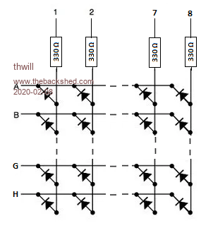 With pins 1-8 and A-H connected directly to 16 of the 20 signal pins of the CMM GPIO connector. I understand I should have no problem illuminating a single LED by setting one of the source pins (1-8) high and the others low, and a corresponding sink pin (A-H) low and the others high. By traversing the matrix, never illuminating more than one LED at a time and relying on persistence of vision I should then be able to display an image. </HowToSuckEggs> My concern is that if I deliberately or accidentally set all the source pins high and only one of the sink pins low, i.e. try to illuminate all the LEDs in a row am I going to "cook" the sink pin by trying to sink ~80 mA into it? Or is there something that is going to save me? Ditto what is going to happen if I try to light all the LEDs in a single column? Am I then going to source too much from the corresponding source pin? If I want to get around any such problems I'm assuming I can just have each pin drive a transistor to switch between sourcing 5V or sinking to ground directly. Or am I still likely to hit limits on how much current I can source/sink through a transistor (bc547 or 2n2222). Thanks again, Tom Game*Mite, CMM2 Welcome Tape, Creaky old text adventures |
||||
| Turbo46 Guru Joined: 24/12/2017 Location: AustraliaPosts: 1593 |
Just to clarify Warpspeed's explanation above. For the multiplexing you would set pin '1' high and any or all of pins 'A' to 'H' low. This means that only one LED on pins 'A' to 'H' would light but pin '1' could be supplying anything from zero to eight LEDs. Then you set pin '1' low and pin '2' high and set pins 'A' to 'H' appropriately and so on until you start again on pin '1'. This means that pins '1' to '8' will need drivers for the multiple LEDs but pins 'A' to 'H' will be OK because they are only feeding one LED. You will need a PNP transistor like a BC557 or similar. The matrix will take about 40mA with all LEDs on so it may be wise to use an external 3.3 volt supply to supply it at least for extended use. As PeterB says the micromites are pretty tough mites so I would expect the Maximite to put up with a bit of abuse for a short time if things go wrong. Bill Keep safe. Live long and prosper. |
||||
| thwill Guru Joined: 16/09/2019 Location: United KingdomPosts: 3848 |
Thanks for the clarifications Bill. By "feeding" in this case you mean sinking the current from? Why PNP rather than NPN? I'm guessing because you'd rather drive the pin of the matrix with a low from the CMM instead of a high? Why is this significant? Presumably you mean all the LEDs in a single column, as opposed to all 64 LEDs ? Why is the 3 or 5V line from the GPIO insufficient? That's good to hear. Have I been confusing myself by thinking that there is an issue with sourcing too much current from a single pin as well as sinking too much? Is it actually the case that if I try and source too much current, I just don't get the current, but otherwise no harm done? Thanks again, Tom Edited 2020-02-09 07:19 by thwill Game*Mite, CMM2 Welcome Tape, Creaky old text adventures |
||||
| Turbo46 Guru Joined: 24/12/2017 Location: AustraliaPosts: 1593 |
Seems like I have only created more confusion. Sorry. 'Feeding' was a bad choice of words. You will be sinking current from the LED anode. You could use an NPN transistor to drive the rows OR a PNP to drive the columns. Just reverse the sense of my description above - set one row to zero at a time and any of the columns to logic '1' then move on to the next. Remember that the transistor will invert the sense of the logic output. The idea of multiplexing is that only one column (or row) is enabled at any one time and any or all of the row (or column) LEDS are enabled at the same time. So yes, there should only be up to eight LEDs in one column (or row) on at any one time. I think the 3.3 volts from the GPIO should be sufficient but I know the 5 volt regulator gets a little warm. The logic level of the Maximite outputs are 0-3.3 volts so you cannot use the 5 volts without some form of level shifting. There is an issue sinking or sourcing too much current from a single pin. As Geoff says you may damage the chip. I suspect it should survive a short term overload. I suggest you proceed slowly. Build the LED matrix and thoroughly test it with clip leads before you connect it to the Maximite. Then experiment with the Maximite. Bill Edited 2020-02-09 09:10 by Turbo46 Keep safe. Live long and prosper. |
||||
| PeterB Guru Joined: 05/02/2015 Location: AustraliaPosts: 639 |
The voltage drop across a typical LED is about 1.8V which means 4.5 mA per LED using 330 ohms and 3.3V. Which gives 36 mA if all 8 LEDs are on and that is a tad more than the 15 mA spec. In my opinion, the chip would get a bit warm but survive but then I could be wrong  and it is a fault condition which will never happen. and it is a fault condition which will never happen.Or you could increase the 330 to 680 and get close to the limit. I will leave my window open so I can hear the bang. Peter |
||||
| Warpspeed Guru Joined: 09/08/2007 Location: AustraliaPosts: 4406 |
For experimental purposes, the safest way to do this might be to connect one eight bit port to a UDN2981 high powered source driver. That can be powered from +5v or even +12v and provide plenty of risk free source power to source your various experiments. Connect a second eight bit port to a ULN2801 high powered sink driver. That will also isolate your precious microcontroller from any overloads or accidents. If you do have a nuclear meltdown event, nothing can get back to harm the microcontroller. If the whole thing were protected by a 250mA fast blow fuse, or a similarly current limited power supply, it should then be just about indestructible. Cheers, ĀTony. |
||||
| PeterB Guru Joined: 05/02/2015 Location: AustraliaPosts: 639 |
Is there a place in this world for a MM buffer? Something that would allow beginners to have a play and not blow things up. It would need to be bi-directional which makes it a bit messy. A 330 ohm resistor provides protection but does have limits. Just thinking Peter |
||||
| bigmik Guru Joined: 20/06/2011 Location: AustraliaPosts: 2870 |
Hi Peter, All, I havent tried that this works but one of those cheap level converters such as this one might work with the same voltage for LV and HV but if not then you can design your LEDs around 5V and use them. They are dirt cheap, this 4 way (first I found on eBay so they may be much cheaper were about $3AUea for a 4 channel, I have seen an 8 channel and I think a 16 cannel out there as well. 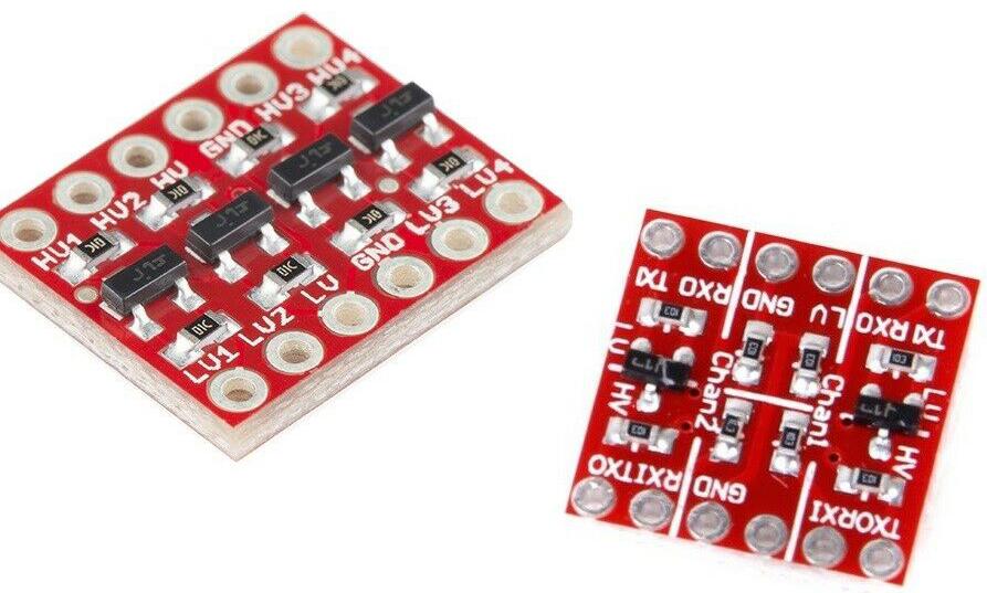 Regards, Mick Mick's uMite Stuff can be found >>> HERE (Kindly hosted by Dontronics) <<< |
||||
| PeterB Guru Joined: 05/02/2015 Location: AustraliaPosts: 639 |
G'Day Mick Those things are interesting. The 3.3V input connects to the S of a FET. The FET G goes to 3.3V and the D goes to 5V through a resistor. If the input is 3.3V the FET is off and the output is pulled to 5V. If the input is 0V the FET is turned on and the output is 0V. It is a clever way to convert from 3.3 to 5 but the output is not driven high just pulled. There are CMOS 3.3V buffers but the output is only a few mA. I have been thinking of a 330 ohm R connrcted to the input of a CMOS buffer. The input to the buffer becomes the MM input and the buffer output becomes the MM output. The buffer input could be used as a high impedance output. As I said before, just thinking. Peter |
||||
| Warpspeed Guru Joined: 09/08/2007 Location: AustraliaPosts: 4406 |
The UDN2981 uses a bipolar transistor on the input, and the input switching threshold is around 1.5v. So it works when driven with 3.3v logic, or 5v TTL or 5v CMOS, or 12v CMOS. Cheers, ĀTony. |
||||
| PeterB Guru Joined: 05/02/2015 Location: AustraliaPosts: 639 |
G'Day Tony That thing is designed to drive high voltage high current inductive loads connected to ground (I think). I, and the kids, have spent the afternoon clearing out my wife's "studio". 30+ years of junk. She is in a nursing home so we are left with the mess. I feel that I have been run over by a bus so I will look into this later. I would like a cab. sav. but I'm not going to open my last bottle until the room is cleared. Peter |
||||
| Page 1 of 3 |
|||||
