
|
|
Forum Index : Electronics : Allans Mad-Inverter Project
| Author | Message | ||||
| shallowal Regular Member Joined: 26/07/2018 Location: AustraliaPosts: 58 |
If I remember correctly, the combined window area of two Aerosharp cores produces a hole 70mm x 20mm. ĀIn theory 14 turns of 10mm outside diameter round wire should fit through that, and it is possible, but only just. Twelve turns might be a more realistic expectation. I found some old underground power cable, but it seems to be 7*1.5mm strands which only works out to around 13mm2. This has an outside dia of about 7.5mm, so I managed to get 2 lots of 9 turns into the core. But I dont think this will suffice :(. Works well with it, though I still dont have a battery to test it properly and already managed to blow up a set of FET's when the input voltage sagged.  Allan Allan |
||||
| Warpspeed Guru Joined: 09/08/2007 Location: AustraliaPosts: 4406 |
Not really much more you can do until you get some serious dc power to test with. Cheers, ĀTony. |
||||
| shallowal Regular Member Joined: 26/07/2018 Location: AustraliaPosts: 58 |
Just a placeholder for a link to a similar problem with the output voltage sensing transformer as I mentioned in my first post. https://www.thebackshed.com/forum/ViewTopic.php?TID=9756&P=5#138793 Allan |
||||
Revlac Guru Joined: 31/12/2016 Location: AustraliaPosts: 961 |
A transformer from plug pack could be used, if one suitable could be found, some of those clock radios had nice small transformers in, tested and working. Be great to see your inverter running again. Cheers Aaron Off The Grid |
||||
renewableMark Guru Joined: 09/12/2017 Location: AustraliaPosts: 1678 |
Try this type of transformer if you don't like the one you're using, that type is very touchy with the adjustment. I think There are a few nib spares in my shed if you want one quicker than china post. Also I can't see great detail from the pic, but just be careful of the tracks and your mounting screws. 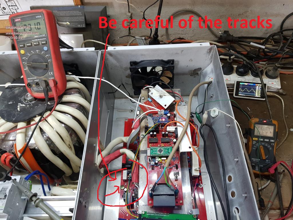 Cheers Caveman Mark Off grid eastern Melb |
||||
| shallowal Regular Member Joined: 26/07/2018 Location: AustraliaPosts: 58 |
Thanks Aaron and Mark. It got on the backburner again when I couldnt source a battery, but I plan now to test it out with the caravan batteries and some spare vehicle donations. One problem I have not been able to solve is how to connect the battery in to the inverter. It was while searching for a solution that I came across the thread with the transformer problem mentioned. I also saw Marks thread about his caravan inverter in which he used some simple terminals thru a piece of plastic sheet. I was thinking about using some brass bolts/threaded rod through some insulated material and then ring terminals on either side, but threaded brass anything is like Unobtainium and as dear as poison. Allan |
||||
| Warpspeed Guru Joined: 09/08/2007 Location: AustraliaPosts: 4406 |
Steel bolts will work just fine bolted through some insulating material. That is what I am now using on my inverter after a plastic Anderson plug melted. Use large flat washers either side of the insulating material, so you can really heave down on those bolts and get them really tight without everything sinking into your insulator. What can happen is everything runs a bit warm and the insulating material can compress slightly over time, and the bolts become a bit loose. That creates more heat and its all down hill from there.... Use high tensile bolts, big wide washers, and it will give you no trouble. Mark is quite right about those screw heads being very close to the pcb tracks. Check out flea-bay, you can buy 3mm nylon screws, 3mm nuts, washers, and plastic spacers. It removes any doubts about something on the pcb shorting down to ground. Cheers, ĀTony. |
||||
| renewableMark Guru Joined: 09/12/2017 Location: AustraliaPosts: 1678 |
Fuse it somehow, maybe like this These welder connectors are good here Or possibly just connect terminals up to a post like this Crimper like this is handy Cheers Caveman Mark Off grid eastern Melb |
||||
| shallowal Regular Member Joined: 26/07/2018 Location: AustraliaPosts: 58 |
Thanks Guys. I really like those welding connectors Mark, I'd never heard of them before. Think I'll start with a bolt through some plastic to start with and adjust things later to suit, thanks Warp. I bought one of those crimpers to do the transformer and inductor so all good there, but you're right about a fuse, need to make provision for that too. Allan Allan |
||||
| renewableMark Guru Joined: 09/12/2017 Location: AustraliaPosts: 1678 |
these are handy too Cheers Caveman Mark Off grid eastern Melb |
||||
| renewableMark Guru Joined: 09/12/2017 Location: AustraliaPosts: 1678 |
I see in your pic you have fitted the std 2 caps (black ones at the end of the control board). Ideally you need to tune the torroid for 75Hz and place the cap/s across the 240v output of the torroid, it will work on the control board, but it's better across the output of the torroid. That's where those connectors in the link above become handy. Edited 2020-05-11 19:44 by renewableMark Cheers Caveman Mark Off grid eastern Melb |
||||
| shallowal Regular Member Joined: 26/07/2018 Location: AustraliaPosts: 58 |
I have been thinking about how to make up something to 'tune' the torroid after seeing your discussion with Warp on another page. I had also been wondering what those 2 capacitors were for on the MAD control board, and it never occurred to me to link the 2 thoughts  . .I finally got to drag the batteries out of the caravan and fire up a bit more load on the inverter. Managed to run my 2400W fan heater without any problem, though my battery connections caused a bit of input voltage sag the output was rock solid. I only have 1 FET per leg ATM and there didnt appear to be any heating at that load, but I didnt run it very long for fear of a voltage dropout. I also checked the idle load and it seems a bit high. With the EG8010 disabled by switching pin6 (SPWMEM) low, I read 0.06A With the whole system running, but no load connected I read 0.9A. There is a bit of transformer "rattle" when the load is less than about 50W but is perfectly fine at 2400W, so I dont think its any problem. I also notice a lot of high frequency noise pretty much everywhere I look and cant imagine how the EG8010 manages to maintain the output with such noisy feedback. Allan |
||||
| Revlac Guru Joined: 31/12/2016 Location: AustraliaPosts: 961 |
You could buy a XR2206 Signal Generator Module Kit, and wait for postage........weeks or month's or they lose it in sydney post dep. Or you could build one if you could find an LM324N somewhere (found them in an old computer monitor main board) and build one with just a few components and two 9volt batteries. There are a few circuit diagrams on googley, there may be some alternative type IC's as well as well. It was fairly easy to do the capacitor tune up. check if the transistor and the 120 ohm resistor see if any are hotter than the other. As for idle current, what was the transformer idle current when tested/driven with a 240Vac supply? If we know this we could work out approximately what the inverter should run with, plus some accessories, meters ans so on. My transformer when driven with a 240Vac supply was about 7watts when running as an inverter that works out to be 21 or so watts plus a bit more for the meters and bits, so total was 25 watts. Hope this is some help. Edited 2020-05-18 21:19 by Revlac Cheers Aaron Off The Grid |
||||
| renewableMark Guru Joined: 09/12/2017 Location: AustraliaPosts: 1678 |
Allan, Tony helped me a lot to work out a good choke for these units. The one used in my van 24v unit and the 48v unit that runs my house is a proven performer. If you can get a hold of 2 sets of the bigger aerosharp chokes that will make an excellent choke. Like here Cheers Caveman Mark Off grid eastern Melb |
||||
| shallowal Regular Member Joined: 26/07/2018 Location: AustraliaPosts: 58 |
Thanks Mark. I am using a single Aerosharp choke ATM, but the only wire I have is some 16mm (I think). So I wound 2 runs in parallel so effectively only got half as many turns as you have with the larger wire. I'll invest in some larger wire and rewind it as you show and see where I get too. Allan |
||||
| Warpspeed Guru Joined: 09/08/2007 Location: AustraliaPosts: 4406 |
Allan, I think the first thing to do is test the bare transformer connected to the grid, and measure the no load idling power of just that. Second step would be to make yourself a suitable choke. The one that Mark made worked out very well, two pairs of Aerosharp steel U cores, and 12 to 14 turns, with 1.0mm to 1.6mm spacers in the air gap would be about right. Last step is to tune the secondary to 75Hz. Now the amount of capacitance required to do that can vary widely, so its no use copying what someone else has. It will need to be tested, and plus or minus 1Hz is about the best I usually end up reaching, which has always worked out well. Its a bit of extra messing about, but it can make a world of difference and avoid a lot of problems. Cheers, ĀTony. |
||||
| shallowal Regular Member Joined: 26/07/2018 Location: AustraliaPosts: 58 |
Thanks Tony/Aaron, Tested the Transformer connected direct to mains, 91mA. so at our nominal voltage of 250V that's around 23W. Seems high compared to Aarons. My Transformer has 4 windings of 128 turns of Aerosharp 2mm wire and it is 2 torroids stacked together. Nothing else connected and the transformer was disconnected from all circuitry other than the choke which is permanently connected to the primary (LV) side but no current would have been flowing anyway. Allan Allan |
||||
| Warpspeed Guru Joined: 09/08/2007 Location: AustraliaPosts: 4406 |
Twenty three watts is fine. Its highly variable, number of turns, number and sizes of cores, and the big unknown is the quality and heat treatment of the steel in the core. No real way of guessing, only by measurement can you know for sure. The support electronics will only be a few extra watts, but that depends on anything extra added, such as big relays, cooling fans, high current LED displays etc... Cheers, ĀTony. |
||||
| renewableMark Guru Joined: 09/12/2017 Location: AustraliaPosts: 1678 |
my fist one was 16watts bare core. Can't remember the others, I think the second one was half that. chinese materials.............. well you get the idea. Cheers Caveman Mark Off grid eastern Melb |
||||
