
|
|
Forum Index : Microcontroller and PC projects : MM: How to measure AC?
| Page 1 of 2 |
|||||
| Author | Message | ||||
| Poppy Guru Joined: 25/07/2019 Location: GermanyPosts: 486 |
Hi guys, has anyone done that yet and how? Is there any special way to measure True RMS somehow or is it actually not so important? Could it be as simple as measuring DC behind a rectifier and calibrating it down to the original AC value? For example: If I take 12V AC and after the rectifier and capacitor I get let�s say 16V DC, then the MM just calculates DC-(DC-AC)?!? And of course it needs a voltage divider, not to fry it! Any experiences around?  Andre ... such a GURU? Andre ... such a GURU? | ||||
| Phil23 Guru Joined: 27/03/2016 Location: AustraliaPosts: 1667 |
Bit of an example here using a cheap module. There are also a few that output full data, V, A, Hz, W, PF etc in a data stream. Cheers. |
||||
| Poppy Guru Joined: 25/07/2019 Location: GermanyPosts: 486 |
Great, thanks. I could not find any other than this particular cheap one on Ebay, but I guess it generally could do the job. Does anyone have any personal experience with it. I want to measure 0-20 VAC, so not up to 250. The output is supposed to be analog 0-5 VDC, probably it could be not precise enough within my lower range!?! Andre ... such a GURU? | ||||
| CaptainBoing Guru Joined: 07/09/2016 Location: United KingdomPosts: 2171 |
there is another module which claims to do the same job but appears require the mains Live passed through a toroid (so no mains connection ebay at a quid fifty I have ordered one of each type to play with. They do appear to be 5V devices with analogue outputs so a v-div will be required to play with the uM |
||||
| Poppy Guru Joined: 25/07/2019 Location: GermanyPosts: 486 |
I think the "blue one" measures voltage (what I need) and "the black one" exclusively current!?!? If so ... of course no reason not to play with!  Andre ... such a GURU? Andre ... such a GURU? | ||||
| matherp Guru Joined: 11/12/2012 Location: United KingdomPosts: 11499 |
Google "precision rectifier" This uses an opamp to create a perfect diode which can then be used to charge a smoothing capacitor. Or there is a very simple circuit for peak detection which can then be used with a bit of math for calculating RMS |
||||
TassyJim Guru Joined: 07/08/2011 Location: AustraliaPosts: 6538 |
I played around with measuring AC mains a few years ago. Now the chips are faster, I intend to revisit the project https://www.thebackshed.com/forum/ViewTopic.php?TID=7158#76007 The interface is simple enough and you can do whatever maths you desire to the samples. Jim VK7JH MMedit |
||||
Chopperp Guru Joined: 03/01/2018 Location: AustraliaPosts: 1126 |
@ TassyJim In your circuit in the link above, where is the connection to PIN(5), the interrupt? Brian ChopperP |
||||
| Poppy Guru Joined: 25/07/2019 Location: GermanyPosts: 486 |
Hi guys, great support!  I will dig some deeper into it, looks really interesting! Andre ... such a GURU? | ||||
| TassyJim Guru Joined: 07/08/2011 Location: AustraliaPosts: 6538 |
The interrupt was just an external trigger for testing. In real life and with faster processors, the intention is to trigger when the peak of any wave is 'different' to the previous wave by a predetermined amount. Jim VK7JH MMedit |
||||
| Volhout Guru Joined: 05/03/2018 Location: NetherlandsPosts: 5930 |
The solution depends on the application. Do you need real time RMS values, or measure RMS once per second. If once per second is sufficient the MM can do it all by himself. Similar to TassyJim's proposal. Use an ADC channel, pre-biassed mid range (1.650V) and AC couple the signal into it. (AC coupling is not necessary, but simplifies the math since you do not have to compensate for DC offset). The MM ADC can run at 70uSec sampling rate at 48MHz clock, and there is a little overhead putting the data into an array, so say 100uSec (or 10kHz sampling rate). For an accurate RMS calculation it is required to do this over an integer number of cycles. Let's say 10 cycles. Then we fill and array with samples that is the size of 10 + 1 = 11 cycles. 1 cycle extra to ensure we capture 11 rising zero crossings (*). 11 cycles at 50Hz (20msec) and 10kHz sampling rate, this is an array of 11 x 200 = 2200 samples. The MM stores 32 bit floats, so that consumes roughly 9 kbyte RAM. After reading the 2200 samples (the MM ADC reading outputs floats 0V...3.3V), the offset (1.650V) has to be subtracted from each sample. (all 2200 individually). Then index of the first (i) and last (j) rising zero crossing in the array has to be found by simply scanning through the array. Then from i to j, sum up the squares of every sample. Divide by the number of samples (= j - i) Then take the square root. That is the RMS value. If you used an input divider (say 1:10) then multiply with the division ration. It is some 30 lines of code, no hardware needed external. Even with lower sampling rate (i.e. 2kHz) you can get very accurate results if your ADC is accurate enough (i.e. 16+ bit). But since the MM ADC is 12 bits only, the proposal is to use 10kHz sampling rate, to get more accurate results. If you like I can see if I can make a circuit and program that demonstrates it tonight. Just reply. Regards, Volhout (*) the sampling frequency (~10kHz, determined by basic interpreter and RC oscillator in PIC32) is not frequency locked to the input sine wave (that can vary anyway), therefore there will be a sampling alignment error (+/- 1 sample). If you ensure that that particular sample that is missing or superfluous has a very small value, the square of that small value is even smaller, so the contribution to the calculated RMS value can be neglected. In a sine wave the "small values" appear at zero crossing. That is why the RMS calculation is executed on the array section between two zero crossings. If the sampling frequency is frequency locked to the input frequency, this technique is not needed and you can simply acquire 10 cycles as 10 x 200 = 2000 samples. Edited 2020-03-11 21:39 by Volhout PicomiteVGA PETSCII ROBOTS |
||||
| Chopperp Guru Joined: 03/01/2018 Location: AustraliaPosts: 1126 |
@TassyJim Thanks, Brian ChopperP |
||||
| Poppy Guru Joined: 25/07/2019 Location: GermanyPosts: 486 |
This would be great, of course! A specific demonstration always is the best guidance! I will try to follow practically, but actually setting up a Duinomite first. Andre ... such a GURU? | ||||
| twofingers Guru Joined: 02/06/2014 Location: GermanyPosts: 1752 |
@volhout Maybe a (modified) CFunction can do the job ...? Like this: http://www.thebackshed.com/forum/ViewTopic.php?TID=8019 ' ' readADCtoArray(INPUT_PIN,Buffer(),buffersize,delay) ' ' "sampletime" is ~250 ticks. For debugging purposes. ' ' Return value is the time in ticks (core timer ticks = 2 CPU cycles = ' 41,666ns @48MHz, i.e. 24000 ticks = 1ms - theoretical) for ' 295 samples (buffersize). ' ' All buffer values are only raw integers. They need to be corrected ' depending on your voltage divider etc. with VCorr. ' ' Known issue: ' It seems the _measurment_ of time is not really correct (diff. ~15%) ' if we read the ADC too/very fast (without waitstates). ' I have no idea why. Maybe the core timer and ExtInp(pin) are somehow connect ' ' written 21-Oct-2015 23:57:37 ' CFunction readADCtoArray 00000000 27BDFFC8 AFBF0034 AFB70030 AFB6002C AFB50028 AFB40024 AFB30020 AFB2001C AFB10018 AFB00014 00C08821 8C960000 8CF00000 40024800 8CC20004 0440001B 0000A021 00A09021 00009821 3C159D00 0000B821 8EA20018 0040F809 02C02021 AE420000 000217C3 AE420004 40024800 0050182B 1460FFFD 00000000 0282A021 40024800 26730001 8E220004 04400007 26520008 5457FFF0 8EA20018 8E220000 0053182B 5060FFEC 8EA20018 02801021 00001821 8FBF0034 8FB70030 8FB6002C 8FB50028 8FB40024 8FB30020 8FB2001C 8FB10018 8FB00014 03E00008 27BD0038 End CFunction C code: #define _SUPPRESS_PLIB_WARNING #include <plib.h> #include "cfunctions.h" long long readADCtoArray( long long *chan, long long *array, long long *elements, long long *delay) { unsigned int pin = *chan; unsigned int e, wait = *delay; //takes 248 ticks to read ADC @48MHz CPU speed unsigned int zero_ticks, current_ticks, sum_ticks=0; // set the core timer to zero (s. delay.c) asm volatile("mfc0 %0, $9": "=r"(zero_ticks)); for(e=0;e<=*elements;e++) { array[e] = ExtInp(pin);//wait; do {// get the core timer ticks asm volatile("mfc0 %0, $9": "=r"(current_ticks)); } while(current_ticks < wait); sum_ticks+=current_ticks; // set the core timer to zero (s. delay.c) asm volatile("mfc0 %0, $9": "=r"(zero_ticks)); } return (sum_ticks); // return sum of ticks } causality ≠ correlation ≠ coincidence |
||||
| Volhout Guru Joined: 05/03/2018 Location: NetherlandsPosts: 5930 |
Hi Poppy, I was a bit optimistic on the sample rate achievable, but I have an example for you anyway. I hope this is of any use. The circuit and algorithm are for measuring AC voltages. In my test I have used a variable transformer driving an small 230V->18V transformer (for isolation, don't want to electrocute myself). The RMS (abbreviation for R(oot), M(ean), S(quare)) is calculated from an array of 800 samples, between 2 zero crossings. The measurement values are accurate (checked against a Fluke multimeter) within 1 percent between 0V and 20V. In this example I display the RMS value at a 16x2 LCD. It also shows how many samples are used to calculate the RMS value. The circuit diagram (measurement input) 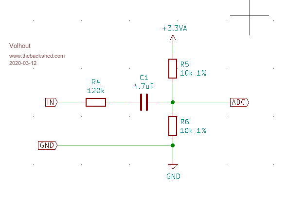 Note that the input is not isolated, if you want to measure mains voltage, you have to insert a transformer for isolation. The test setup 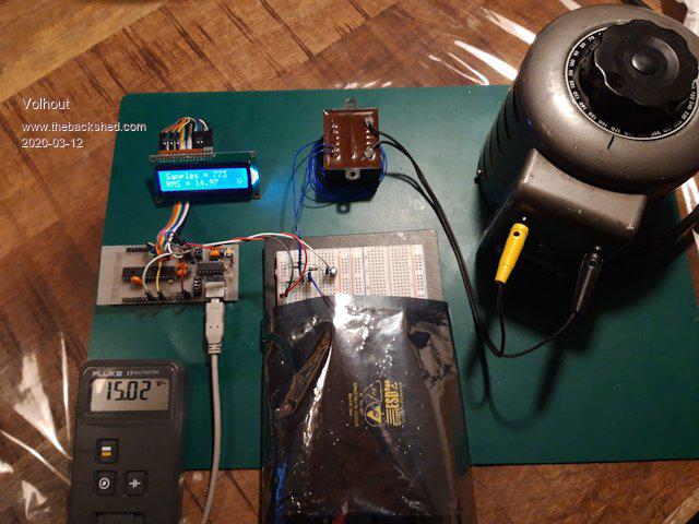 The LCD displaying samples and RMS value 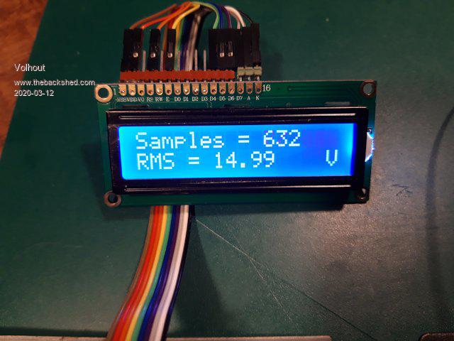 The program (I tried to make it readable) '+--------------------------------------------------------------+ '| � � � � � � � � � � RMS convertor for MX170 � � � � � � � � �| '+--------------------------------------------------------------+ ' The RMS value of a signal is the R(oot)M(ean)S(quare) value. ' It is calculated by adding up the squares of the input signal ' The mean of these squares is rooted. This process is explained ' in the steps below. ' This example uses the ADC in the PIC32MX170 to measure the ' AC input signal. Output is displayed at a 16x2 LCD. '---------------------- �Defines ------------------------------- ADCpin = 23 � � � � ' ADC input pin Total = 800 � � � � ' array size for measuring 220mSec @ 48MHz Offset = 1.650 � � �' numeric offset at 3.300V CalValue = 24.85 � �' gain factor attenuator and AC coupling @ 50Hz Option explicit '------------------------- Dim Variables -------------------- Dim Sample!(Total) Dim SumSQ!, Value! Dim i%,j%,a% '---------------------- Initialize hardware ------------------- SetPin ADCpin, AIN �' initialize ADC CPU 48 � � � � � � �' maximum speed for the MX170 'LCD LCD init 4,5,6,7,2,26 LCD 1,1,"Samples = � � � " LCD 2,1,"RMS = � � � � �V" '--------------------------- Measuring ---------------------- Do � �'sample input signal � �For i%=1 To Total � � �Sample(i%)=Pin(ADCpin)-Offset � �Next i% � �'find zero crossings � �i%=0:j%=Total-1 � �'first zero crossing in array � �Do � � �i%=i%+1 � �Loop Until(Sample(i%)>0 And Sample(i%+1)<0) � �'last zero crossing in array � �Do � � �j%=j%-1 � �Loop Until (Sample(j%)>0 And Sample(j%+1)<0) � �'calculate SQUARES � �SumSQ!=0 � �For a%=i% To j% � � �SumSQ! = SumSQ! + (Sample!(a%)*Sample!(a%)) � �Next a% � �'calculate MEAN � �SumSQ! = SumSQ!/(j%-i%) � �'calculate ROOT � �Value! = Sqr(SumSQ!) � �'display values on 16x2 LCD � �LCD 1,11,Str$(j%-i%) � �LCD 2,7,Left$(Str$(Value!*CalValue!),5) Loop I hope this can help you on your way... Regards, Volhout P.S. the "CalValue" can be calculated from accurately measured 3.3V, resistor and capacitor values. But for the demo, the value is just "tuned" to get full range identical values to the Fluke multimeter, and values between 1V and 20V are checked for accuracy (linearity). P.P.S. the accuracy increases with the number of samples. With 2000 samples it is better than 0.5%, but measurements take 1 second. Edited 2020-03-12 07:19 by Volhout PicomiteVGA PETSCII ROBOTS |
||||
| Poppy Guru Joined: 25/07/2019 Location: GermanyPosts: 486 |
Geweldig, bedankt! I will try to set it up on a Duinomite first not being sure about its actual speed. ... but my set up for the power source already looks very similar. 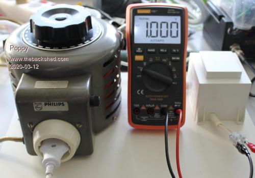 Andre ... such a GURU? Andre ... such a GURU? | ||||
| Volhout Guru Joined: 05/03/2018 Location: NetherlandsPosts: 5930 |
Hi Poppy, Some notes on the circuit: R5 and R6 (10k 1%) are used to centre the signal around the middle of the ADC. These resitors need to accurate to get exactly at the middle of the range, else they create an offset (and a measuring error). To minimize the offset you can either - adjust resistor values to get exactly middle of your 3.3V - change the "Offset" value in the program to display exactly 0.00V RMS when there is no input voltage (short input pin to gnd). The ADC has 3.3V range, the centre is 1.65 V. Therefore the input signal can be +/- 1.65V max at the ADC. The current component values (R4=120k, R5/R6=10k) attenuate the input signal (120+5)/5 = 25 times. So the maximum measurement range is +/- 25x1.65 = +/- 41V. If a sine wave is applied that is maximum 41/1.4 = 30Vac If you need more range, you will have to increase resistor R4. Capacitor C1 can be a low voltage part. Typically it has only 1.65V across it. Protection diodes are not in this circuit since the R4(120k) limits the current sufficiently to rely on the internal protection diodes inside the MX170. If you are in a very dirty electrical environment (welding equipment, large pumps, Tesla coils...) you may want to add them though. The duinomite is an MX470 (same as maximite), so it should run faster than the MX170. Remove the CPU 48 command from the program, it will throw you an error. Edited 2020-03-12 21:07 by Volhout PicomiteVGA PETSCII ROBOTS |
||||
| Poppy Guru Joined: 25/07/2019 Location: GermanyPosts: 486 |
Thanks! I will check it out! Andre ... such a GURU? | ||||
| twofingers Guru Joined: 02/06/2014 Location: GermanyPosts: 1752 |
I don't think so (PIC32MX795F512H).  causality ≠ correlation ≠ coincidence |
||||
| Volhout Guru Joined: 05/03/2018 Location: NetherlandsPosts: 5930 |
Right.... Sorry... Anyway, it seems to run at 80MHz according datasheet, so a bit faster than the MX170. PicomiteVGA PETSCII ROBOTS |
||||
| Page 1 of 2 |
|||||
| The Back Shed's forum code is written, and hosted, in Australia. | © JAQ Software 2026 |
