
|
|
Forum Index : Electronics : 150V 45A MPPT - roll your own
| Author | Message | ||||
| nickskethisniks Guru Joined: 17/10/2017 Location: BelgiumPosts: 409 |
Hi, don't know if it's a good suggestion or already to late, but maybe we can have the option to solder the wires directly to the pcb. Screw terminals are good for debugging and changing boards, but once up they will stay there. :) Something like this: 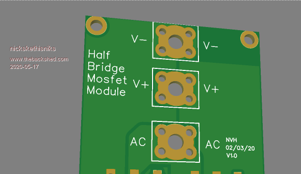 If I understand correctly we just need an auxiliary 12V power supply, I'm thinking of using more stuff like this in the future: https://www.tme.eu/be/nl/details/ddr-15l-12/voedingen-op-din-rail/mean-well/ They should be more reliable then the Chinese supplies, although they are probably designed/produced in China as well. Now finding one with the right input range, or adding a Zener in series with it. Or could we design a simple supply ourselves? |
||||
| wiseguy Guru Joined: 21/06/2018 Location: AustraliaPosts: 993 |
Hi Nicks, I will provide a 4mm plated through hole and masked off area. I had thought of this but was alittle concerned about impedance, but maybe a brass or nickel/brass screw soldered from the underside or screw and nut soldered both sides of the PCB facing upwards would allow a terminal and another nut screwed down to fasten it effectively ? Another PCB update coming shortly Peter..... If at first you dont succeed, I suggest you avoid sky diving.... Cheers Mike |
||||
| poida Guru Joined: 02/02/2017 Location: AustraliaPosts: 1388 |
I like solder onto PCB. Just a preference. wronger than a phone book full of wrong phone numbers |
||||
mason Regular Member Joined: 07/11/2015 Location: CanadaPosts: 86 |
Poida, if you parallel two or three of these will you need two or three control boards or can you just use one? |
||||
| nickskethisniks Guru Joined: 17/10/2017 Location: BelgiumPosts: 409 |
You can order 2 boards for me Peter. Thanks in advance. |
||||
| poida Guru Joined: 02/02/2017 Location: AustraliaPosts: 1388 |
Manson, I think each board needs a controller. By all means experiment with parallel if you like. I find it easier to see how things work if there are one or more self contained boards, doing what they individually are required to do. Limit output current, maximise output power, look after battery voltage limits etc. wronger than a phone book full of wrong phone numbers |
||||
| mason Regular Member Joined: 07/11/2015 Location: CanadaPosts: 86 |
Thanks for the info Poida. |
||||
| poida Guru Joined: 02/02/2017 Location: AustraliaPosts: 1388 |
The brainboard is completed for Wiseguy's PCB of the converter. Through hole components. 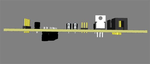 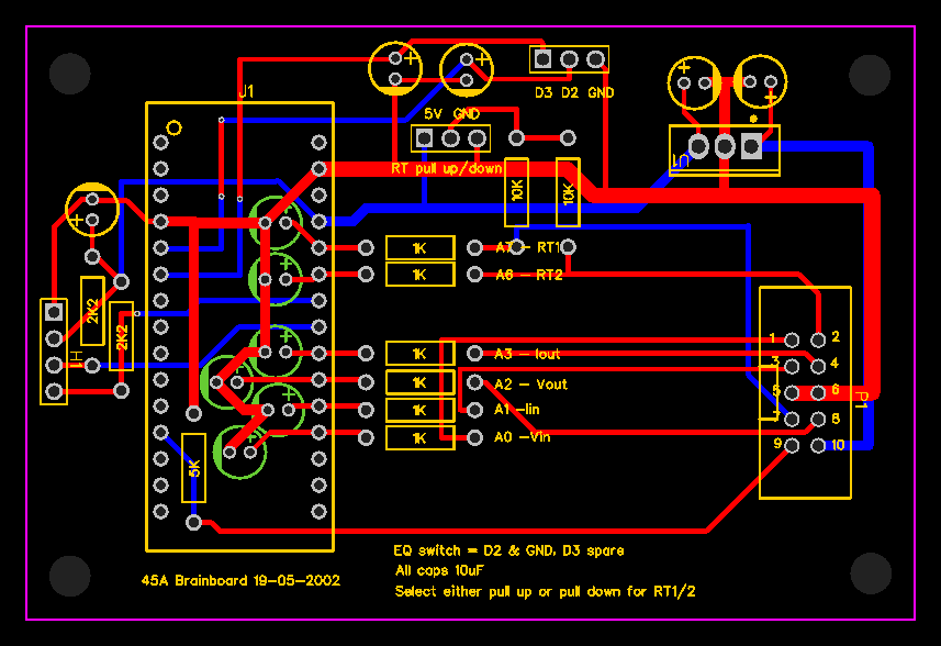 � WG's PCB 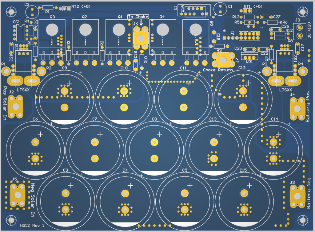 Edited 2020-05-19 12:44 by poida wronger than a phone book full of wrong phone numbers |
||||
| poida Guru Joined: 02/02/2017 Location: AustraliaPosts: 1388 |
Ordered 25 of both boards. wronger than a phone book full of wrong phone numbers |
||||
Revlac Guru Joined: 31/12/2016 Location: AustraliaPosts: 961 |
Boards are looking nice. Some 470uf 200v capacitors can be scrounged from (about half a dozen) old ATX power supplies, if need be.  Cheers Aaron Off The Grid |
||||
| poida Guru Joined: 02/02/2017 Location: AustraliaPosts: 1388 |
that's the whole idea! wronger than a phone book full of wrong phone numbers |
||||
| mason Regular Member Joined: 07/11/2015 Location: CanadaPosts: 86 |
Poida, I'll take a couple sets if there are some left, tried to pm you a couple days ago but don't think it worked. Thanks |
||||
| tinyt Guru Joined: 12/11/2017 Location: United StatesPosts: 431 |
Hi Poida, If it is not yet too late, I would like to have a set. Thanks. |
||||
| poida Guru Joined: 02/02/2017 Location: AustraliaPosts: 1388 |
Tinyt: For sure you can have 2. I ordered 25, which is 5 extra. Now it's 3 extra. Mason: I have 2 for you as well. I included your 2 in the total of 20. wronger than a phone book full of wrong phone numbers |
||||
| ryanm Senior Member Joined: 25/09/2015 Location: AustraliaPosts: 191 |
How would you like to get payment poida? If I can get a acc no & bsb I can direct transfer the money. |
||||
| mason Regular Member Joined: 07/11/2015 Location: CanadaPosts: 86 |
Thanks Poida, when you have time let me know what I owe you. They will be posted to Canada, Ontario. |
||||
| poida Guru Joined: 02/02/2017 Location: AustraliaPosts: 1388 |
Once I get the boards I will know post and packaging costs. They will go into a good quality postpack (internal bubble wrap, tough outer cardboard). Last time when I did the nanoverter board, I sent PMs to the recipient after I posted since only then did I know the cost. wronger than a phone book full of wrong phone numbers |
||||
renewableMark Guru Joined: 09/12/2017 Location: AustraliaPosts: 1678 |
Probably need a list of components to order. Control board Electro caps 10uf x6 16v? 2k2 x2 1k x6 10k x2 U1 ? P1 10 pin socket like here Nano header pins like here Power board 13x 470uf electro caps 200v or above. The rest on the board isn't marked with values. Choke, I was thinking this but they are out of stock for a while These are in stock but dearer Cheers Caveman Mark Off grid eastern Melb |
||||
| Warpspeed Guru Joined: 09/08/2007 Location: AustraliaPosts: 4406 |
Mark, make absolutely certain those 470uF electrolytics are of the correct physical size, and have the right footprint. Cheers, �Tony. |
||||
| poida Guru Joined: 02/02/2017 Location: AustraliaPosts: 1388 |
U1 is a 7805 linear regulator (TO-220) The chokes I am developing the project with are based on 1 of the expensive ones with zero gap a and another of them with a 1mm gap. I have 7 1/2 turns, giving about 47uH This inductor with 1mm gap and 7 1/2 turns saturates at about 80A or 90A from testing with the pulse inductor test rig. I have not seen saturation at 2200W at 57V input for the prototype charge controller. This ends up costing more than 4x the ones out of stock but that's the way it goes. I was happy to spend $52 on a choke if it prevented the inverter blowing up. Now I build inverters using 2 of these chokes in series. RS have stock of these which are the same size, zero gap but less Al rating, 8700 instead of 9700. Maybe good enough, certainly good enough if you use 2 in series. wronger than a phone book full of wrong phone numbers |
||||
